1
PRESSURE MEASUREMENT DPI 515 PRECISION PRESSURE CONTROLLER/CALIBRATOR OPERATOR'S MANUAL K245 © Druck Limited 2000 This document is the property of Druck Limited and may not be copied or otherwise reproduced, communicated in any way to third parties, nor stored in any Data Processing System without the express written authority of Druck Limited. Druck Limited, Fir Tree Lane, Groby, Leicester LE6 0FH, England. Tel: (0116) 231 7100 Fax: (0116) 231 7103 K245 Issue No.2 DPI 515 User Manual i DPI 515 PRECISION PRESSURE CONTROLLER/CALIBRATOR DPI 515 Precision Pressure Controller/Calibrator © Druck Limited 2000 This document is the property of Druck Limited and may not, either in part or whole, be copied or otherwise reproduced, communicated in any way to third parties, or stored in any Data Processing System, without the express written authority of Druck Limited. K245 Issue No. 2 ii K245 Issue No. 2 DPI 515 User Manual DPI 515 User Manual iii CONTENTS Section Title Page 1 1.1 INTRODUCTION………………………………………………………. Description……………………………………………………………… 1-1 1-1 2 2.1 2.2 2.3 2.4 2.5 2.6 2.7 SAFETY AND ENVIRONMENTAL…………………………………... Hazard Triangle………………………………………………………… Pressure Safety………………………………………………………… Electrical Safety………………………………………………………... Toxic Materials…………………………………………………………. Repair and Maintenance……………………………………………… Safety Conformity……………………………………………………… Re-cycling of Materials………………………………………………… 2-1 2-1 2-1 2-1 2-1 2-1 2-1 2-2 3 3.1 3.2 3.3 3.4 3.5 3.6 3.7 INSTALLATION………………………………………………………… Safety…………………………………………………………………… Ventilation………………………………………………………………. Mounting………………………………………………………………… Pressure Connections…………………………………………………. Pressure Supplies……………………………………………………… Electrical Connections………………………………………………… Computer Connections………………………………………………... 3-1 3-1 3-1 3-1 3-2 3-4 3-8 3-10 4 4.1 4.2 4.3 4.4 4.5 4.6 4.7 4.8 4.9 4.10 4.11 OPERATION…………………………………………………………… General………………………………………………………………….. Local and Remote Operation…………………………………………. Preparing for Operation……………………………………………….. Controls and Indicators………………………………………………... First Time Operation…………………………………………………… Basic Task Screen…………………………………………………….. Measure and Control Modes…………………………………………. Using the Task Menu………………………………………………….. Task Menu Functions………………………………………………….. Using the Set-up Menu………………………………………………... Set-up Menu Functions……………………………………………….. 4-1 4-1 4-1 4-2 4-2 4-4 4-4 4-7 4-7 4-8 4-11 4-13 K245 Issue No. 2 iv DPI 515 User Manual Section Title Page 5 5.1 5.2 5.3 5.4 5.5 CALIBRATION…………………………………………………………. Instrument Calibration Status………………………………………… Pressure Unit Conversions…………………………………………… Calibration Check……………………………………………………… Calibration Correction…………………………………………………. Valve Correction……………………………………………………….. 5-1 5-1 5-1 5-1 5-2 5-3 6 6.1 6.2 6.3 6.4 6.5 6.6 USER MAINTENANCE……………………………………………….. Safety…………….……………………………………………………... Fuse Replacement…………………………………………………….. Valve Replacement……………………………………………………. Cleaning………………………………………………………………… Fault Diagnosis………………………………………………………… Approved Service Agents…………………………………………….. 6-1 6-1 6-1 6-2 6-3 6-3 6-4 AI AI.1 AI.2 AI.3 APPENDIX I……………………………………………………………. Instrument Specification………………………………………………. Options………………………………………………………………….. Accessories…………………………………………………………….. AI-1 AI-1 AI-5 AI-6 AII AII.1 AII.2 AII.3 APPENDIX II…………………………………………………………… DPI 510/520 Emulation – Supported Commands………………….. DPI 510 Emulation Limitations……………………………………….. Ruska 7000 Emulation……………………………………….. AII-1 AII-1 AII-2 AII-3 AIII AIII.1 APPENDIX III…………………………………………………………... Barometric Reference Operation…………………………………….. AIII-1 AIII-1 AIV AIV-1 AIV-2 APPENDIX IV ………………………………………………………… Aeronautical Units Option…….…………………..………………….. Aeronautical Task…………………………………………………….. Altitude…………………………… ……………………………. Airspeed…………………………………………………………. CAS and Mach…………….……………………………………. Mach…..…………………………………………………………. AIV-1 AIV-1 AIV-1 AIV-1 AIV-2 AIV-3 AIV-4 K245 Issue No. 2 DPI 515 User Manual v Section Title Page AV APPENDIX V…...………………………………………………………. Ancillary Equipment……………………………………………………. Supplier’s Addresses………………………………………………….. Pressure Connections and Fittings………………………………….. Vacuum System for DPI 515……...………………………………….. AV-1 AV-1 AV-2 AV-3 AV-3 K245 Issue No. 2 vi K245 Issue No. 2 DPI 515 User Manual 1: Introduction 1 INTRODUCTION 1.1 Description 1-1 The DPI 515 is a high performance precision pressure controller capable of feeding controlled pressure into leak tight systems and holding pressure where very small flows are required. The controller offers automatic control valve compensation thereby giving dependable operation over long, sustained periods of use with a variety of system pressures and volumes. The DPI 515 is designed for benchtop use or for mounting in a standard 19 inch rack system using an optional rack mounting kit. All pneumatic and electrical connections are made at the rear panel of the instrument for neatness and ease of installation. In Local mode the instrument is controlled via a graphics backlit LCD, softkeys associated with the display, a keypad and a rotary control. The display and associated controls are all situated on the front panel of the instrument. RS232 and IEEE-488 are fitted as standard, allowing easy remote control and configuration for integrated computer driven systems. The DPI 515 uses the SCPI (Standard Commands for Programmable Instruments) instrument command language to provide standardisation with other instruments. In addition, emulation supported command codes are provided for DPI 510, DPI 520 and Ruska 7000 controllers. Further technical information and notes on applications are available on the Druck web site at www.druck.com. K245 Issue No. 2 1-2 K245 Issue No. 2 DPI 515 User Manual 2: Safety and Environmental 2 SAFETY AND ENVIRONMENTAL 2-1 This product has been designed to be completely safe when installed and operated in accordance with its ratings and procedures published in this document. Because this instrument has a high voltage electrical supply and high pressure supplies, professional installation standards must be used. Please refer to Installation (Section 3) for details of supply connections. Please pay close attention to the safety instructions given on this page and elsewhere in the handbook. They have been designed to protect the User from risk of injury. 2.1 Hazard Triangle Potentially hazardous operations are indicated in the text by means of the hazard warning triangle. Specific warnings relating to each section of the handbook are given at the beginning of that section. 2.2 Pressure Safety On no account permit pressures greater than those indicated on the rear panel as the supply pressures to be connected to the instrument. The output pressure from ranges above 70 bar cannot be connected to the outlets of any other DPI 515 Pressure Controllers or even a second range within the same instrument. The outlet of these high pressure ranges must be connected directly to the pressure system or Unit Under Test (UUT). 2.3 Electrical Safety The instrument is designed to be completely safe when used with the Options, Accessories and replacement parts supplied by the manufacturer. Attention is drawn to the installation of the electrical supply 2.4 Toxic Materials There are no known toxic materials employed in construction of the DPI 515. 2.5 Repair and Maintenance The instrument must be maintained and repaired by the manufacturer or a competent person. A list of Druck Approved Service Agents is given in Section 6.6 of this manual. 2.6 Safety Conformity This product meets the requirements of all relevant European safety directives. The product carries the CE mark. K245 Issue No. 2 2-2 2.7 DPI 515 User Manual Re-cycling of Materials When disposing of this product, please consider the re-use of materials. The major materials used are: • • • • Sheet metal case parts: Front panel, rotary control, rack handles: Manifolds to 70 bar: Manifolds above 70 bar: K245 Issue No. 2 steel ABS Aluminium 6082 Aluminium Bronze CA104 3: Installation 3-1 3 INSTALLATION 3.1 Safety IT IS ESSENTIAL THAT THE INSTALLATION OF ELECTRICAL AND PNEUMATIC SUPPLIES BE UNDERTAKEN BY A COMPETENT PERSON. 3.2 Ventilation The cooling air outlet at the top left hand corner of the rear panel of the instrument must not be covered or obstructed in any way. A free flow of air around the instrument should be provided where possible, especially at elevated operating temperatures. 3.3 Mounting There are two ways in which the instrument may be used: • • Free standing. Rack mounted in a standard 19 inch rack. NOTE: 3.3.1 The rack mounting kit is not part of the standard package and is offered as an option. See Appendix I, Option D. Free Standing For benchtop use, two feet are fitted at the base of the unit to provide a comfortable viewing angle for the operator. 3.3.2 Rack Mounting (Fig. 3.1) To convert the DPI 515 instrument for rack mounting, a rack mounting kit is required. This comprises two support arms, which slide into slots either side of the rear panel, and two handle brackets which must be screwed in to the side panels at the front of the instrument. Before installation, ensure that there is sufficient length of cable and pipe for the installation and removal of the instrument. All connections are made at the rear of the instrument. Allow enough space for cables and pipes for when the instrument is pushed back and secured in the rack. Secure the two handle brackets to the front sides of the instrument using the four M6 Cap Screws provided. K245 Issue No. 2 3-2 DPI 515 User Manual NOTE: There are left and right hand side handle brackets styled to match the front panel contours. Secure the two rear support arms to the rear tappings of the rack such that the blades protrude inside the rack. Position the instrument in the rack such that the blades on the rear support arms slide into the slots on the rear panel of the instrument. Remake electrical, communications and pressure connections on the instrument rear panel, slide the instrument fully into the rack and secure the handle brackets to the front tappings of the rack. Fig. 3.1 – Rack Mounting Arrangement 3.4 Pressure Connections (Fig. 3.2) 3.4.1 Pressure Safety Instructions ALWAYS CHECK FOR TRAPPED PRESSURE BEFORE CONNECTION OR DISCONNECTION OF PRESSURE COUPLINGS. ENSURE THAT CORRECTLY RATED PIPES AND FITTINGS ARE USED. OBSERVE SPECIFIED SUPPLY PRESSURE OF THE INSTRUMENT. K245 Issue No. 1 3: Installation 3.4.2 Connection 3-3 All pneumatic connection ports are situated on the rear panel of the instrument. Before connecting to a pneumatic port ensure that there is sufficient length of pipe for easy installation and removal of the instrument for calibration and maintenance purposes. The use of flexible piping is recommended wherever practical. THE SUPPLY PRESSURE MUST BE IN THE SPECIFIED SOURCE PRESSURE RANGE. WHEN CONNECTING A NUMBER OF INSTRUMENTS OF DIFFERING RANGES TO A COMMON SOURCE, APPROPRIATE EXTERNAL PRESSURE REGULATORS MUST BE FITTED TO EACH INSTALLATION. Fig. 3.2 – Pneumatic Connections 3.4.3 Pressure Ranges An instrument can be fitted with one or two pressure ranges. Each range has its own independent connections with the exception of the reference connection. Each range can be fitted with a gauge (reference to atmosphere via the reference port) sensor. Pressure supplies and connections must be considered separately for each range as the maximum, full scale pressures for each range may differ widely. Different fittings/pipework and procedures may be applicable. K245 Issue No. 2 3-4 3.5 DPI 515 User Manual Pressure Supplies (Figs. 3.3, 3.4 and 3.5) The use of a suitable pneumatic pressure medium at the correct supply pressure for each range is essential (see specification in Appendix I). Instrument calibration is unaffected by the supply gas density and type. Each range in the instrument requires a positive supply. If absolute or negative gauge operation is required, or if fast response around atmospheric pressure is required then a vacuum source should also be connected to the negative supply. Supplies should be provided with an isolation valve and any other necessary conditioning equipment. On some supplies it may be necessary to remove water, oil or particulate contamination. Any water present must be in vapour form, i.e. noncondensing under any circumstances. There should be no corrosive material in the supply. Oil must be completely removed as this will lead to rapid deterioration of the control valves. NOTE 1 (Figs. 3.3, 3.4 and 3.5): Only Range 1 connections apply to single range instrument. NOTE 2 (Figs. 3.3, 3.4 and 3.5): F1 & F2 are in-line filters (Option G). NOTE 3 (Figs. 3.3 ,3.4 and 3.5): Some supply components may not be required – refer to text. NOTE 4 (Figs. 3.4 and 3.5): Silencers are supplied with the instrument. NOTE 5 (Fig. 3.5): Important – Do not connect Outlets together. Fig. 3.3 – Pneumatic Connections up to 70 bar (without vacuum supply) K245 Issue No. 1 3: Installation 3-5 Fig. 3.4 – Pneumatic Connections up to 70 bar (with vacuum supply) Fig. 3.5 –Pneumatic Connections above 70 bar K245 Issue No. 2 3-6 3.5.1 DPI 515 User Manual Positive Supply The positive pressure supply will need to be regulated for each range. The supply is 110% of range (FS ± 5%). The range supply rating label gives the required supply value for that range. Recommended regulators are given in Appendix V. 3.5.2 Negative Supply The instrument must be configured to work with or without a negative supply, see Setup/Supervisor/Negative supply. Where there is no negative supply (vacuum pump), positive pressure is released from the system to atmosphere through the negative supply port. This discharge from the negative port may be piped away to a place where this discharge causes no disturbance or hazard. Alternatively a silencer may be fitted to the negative supply port to reduce acoustic noise and air flow. The need for a negative supply The general rule for supply pressures is that there must be a differential of 10% of full scale between the supply pressure and the maximum outlet pressure. This means that when the instrument is working at its positive or negative full scale, there must still be a pressure differential between supply and outlet to drive flow when required. Therefore, any controller required to control around atmospheric pressure or below requires a vacuum pump or other negative supply connected to the negative supply port for optimum operation. If the vacuum supply is not provided then, as the outlet pressure approaches atmospheric pressure, the differential pressure will approach zero resulting in a reduced flow to the outlet. The effect is to increase the time to control to atmosphere, especially with large user volumes, and to increase overshoot at low pressures. If there is a small zero offset in the instrument, it may actually aim for a pressure slightly below atmosphere and fail to reach this level. This condition can increase valve wear. With high pressure instruments (above 70 bar) the resolution around atmospheric pressure decreases and the overshoot and added time to reach zero are not significant. A vacuum supply is essential for: • • • Absolute ranges Negative gauge ranges Where accurate and long duration control at atmospheric pressure is required. K245 Issue No. 1 3: Installation 3-7 A vacuum supply will improve: • • • • Time to reduce system pressure especially at low pressures, below 2 bar FS. Control stability at pressures around atmosphere Overshoot at low pressures. Control valve lifetime. The negative supply for absolute control does not need to be regulated. It is recommended that the output of the vacuum pump should be less than 35 mbar. Any variation between this and absolute zero will have no effect on instrument operation. Precautions must be taken against oil transfer to the instrument. A venting solenoid connected to atmosphere and the pump is recommended. When the pump supply is disconnected the valve opens allowing atmospheric pressure to enter the pump directly rather than via the pipe to the instrument. If this precaution is not taken, oil may progressively migrate up the supply pipe and into the instrument. When installing a vacuum supply for use with a unit above 2 barg positive full scale, care should be taken to protect the vacuum pump against the dumping of positive pressure by the controller into the vacuum pump. This may result in a degradation of pump performance and a loss of vacuum. It is recommended that a release valve is used in the negative supply which will vent pressure to atmosphere if the vacuum pressure rises above atmospheric pressure. The valve should be installed on the instrument side of a volume which is approximately equal to the system volume. The volume acts as a buffer against rapid pressure rise giving the valve time to open and the pump time to reduce the pressure. Wide bore vacuum pipe can have adequate volume but it is still recommended to protect it from over pressure with a release valve. 3.5.3 Vent Port The Vent port is active when the instrument performs either a zero or vent operation. Gas at the outlet pressure will then be released from the port. During a zero operation only the internal volume of the instrument is released. During a vent operation the whole of the user’s system is de-pressurised through the vent port but only after most of the pressure has been released under rate control via the negative supply port. The Vent port should have an unobstructed path to atmosphere. A silencer may be fitted to the Vent port to reduce acoustic noise and safely dampen gas exhaust when venting. 3.5.4 Outlet Port The Outlet port provides the controlled pressure output to the unit under test (UUT). Single range instruments have one outlet. Dual range units have two outlets, one for each pressure range. The outlet ports on a dual range instrument, up to 70 bar, can be piped together and connected to the UUT. (Configure the instrument in SETUP/ Supervisor/System/Stand alone). K245 Issue No. 2 3-8 DPI 515 User Manual Ranges above 70 bar must not be connected to the outlet of any other range. Outlets of ranges above 70 bar must be piped independently to UUT. If UUT is contaminated, additional filters should be connected in-line between Outlet port and UUT to prevent contamination of the instrument. 3.5.5 Reference Port The reference port allows connection to the negative (reverse) side of gauge transducers and, if fitted, the barometric reference (Option A). The reference connection is always made to the port marked ‘Reference Connection’ which is a part of the Range 1 pressure connection assembly. The references of any gauge sensors (range 1 or Range 2) are connected to this port. The reference connection is normally exposed to atmosphere but, when gauge transducers are fitted without barometric reference small pressures can be applied (see Instrument Specification in Appendix I). The instrument will show the pressure difference between the reference and outlet ports when in gauge mode. This is not true differential operation as there is no differential calibration of the sensor. When a barometric reference transducer is fitted this transducer senses atmospheric pressure via the reference port, thus the port MUST be exposed to atmosphere. The reference connection should be actively employed during precision low pressure work. The instrument controls pressure relative to the pressure on the reference port. Thus if there are atmospheric pressure disturbances, these will be tracked by the controller and appear on the pressure outlet as apparent instability. In order to obtain a stable controlled pressure, the reference port should be ‘damped’ by connecting a large volume with a small leak to atmosphere. This forms a low pass filter damping out atmospheric transients. The controller and UUT references should also be interconnected if possible to provide a common reference to atmosphere. 3.6 Electrical Connections (Fig.3.6) There are facilities for an ac power input supply and low voltage dc electrical connections on the rear panel of the instrument. 3.6.1 Electrical Safety Instructions THE OPERATING VOLTAGE RANGE IS MARKED ON THE REAR PANEL OF THE INSTRUMENT. K245 Issue No. 1 3: Installation 3-9 IT IS ESSENTIAL THAT THE GROUND LEAD (COLOURED GREEN/YELLOW) IS CONNECTED TO THE AC SUPPLY PROTECTIVE SAFETY GROUND. BEFORE MAKING ANY ELECTRICAL CONNECTIONS TO THE REAR PANEL, ISOLATE THE INCOMING POWER SUPPLY.BEFORE REMOVING ANY COVERS, ISOLATE THE INSTRUMENT FROM ALL ITS SUPPLIES. 3.6.2 AC Input Power Supply Connection The ac power supply connection is made on the rear panel of the instrument. To connect power to the instrument proceed as follows: • • • Insert the moulded IEC connector (1) into the power supply inlet assembly (5). Set the ON/OFF switch (4) to ON. Check that the front panel display is on. Key: 1 2 3 4 IEC power connector Fuse carrier Fuse ON/OFF switch 5 6 7 8 Power supply inlet assembly DC output Logic input Logic output Fig. 3.6 – Electrical Connections 3.6.3 Low Voltage Electrical Connections 24V DC Output An output with a nominal voltage of 24V dc is provided on a two part connector block for energising external equipment. The supply is protected within the instrument by a self resetting fuse. K245 Issue No. 2 3-10 DPI 515 User Manual Logic (switch) Input A logic input is provided on a two part connector block which can be used to trigger the instrument from a pressure switch contact during the Pressure Switch Task (see Section 4.9.5). A voltage between 5 and 24V dc or ac represents a logic 1. Logic Outputs Two volt free contacts are provided for interfacing with external equipment (see Instrument Specification in Appendix I for contact ratings). NOTE: 3.7 There is a common connection between one pole of each logic output contact. The contacts have a resistor/capacitor snubber circuit which restricts the upper operating frequency as shown in the specification. The contacts may be used in conjunction with the 24 Vdc output to operate external devices such as indicator lamps, electrically operated valves, signal to a PLC, etc. Computer Connections (Fig. 3.7) The instrument provides RS 232 and IEEE 488 communication ports for interfacing with a controlling (host) computer. Connections for both facilities are made on the rear panel of the instrument. To connect the interfaces, fit the appropriate connectors into the relevant sockets and tighten the securing screws. NOTE: Whilst both interfaces are provided only one can function at a time. Fig. 3.7 – RS232 and IEEE 488 Connections K245 Issue No. 1 3: Installation 3.7.1 RS 232 Interface 3-11 When using the RS 232 interface, a cable must be run directly from the instrument to a suitable port on the computer in a simple ‘point to point’ link. Instrument Instrument Function Control Line Connector Type RxD(I/P) Lemo Conn. pin No. 1 9-way D-type pin No. 3 TxD(O/P) 6 2 GND 3 5 CTS(I/P) 2 7 RTS(O/P) 5 8 Pulled high internally Not Used 4 1 N/C 4 4 6 Connector Shell Connector Shell Pulled high internally Equipment Chassis Signal Direction • • • • • • • • • RS 232 Terminology Computer/Printer Connector Type TxD 9-way D-type pin No. 3 25-way D-type pin No. 2 RxD 2 3 GND 5 7 RTS 7 4 CTS 8 5 RLSD (DCD) DTR 1 8 4 20 6 6 - 1 DCR DCE Ready Cable Screen Table 3.1 – RS 232 Connections K245 Issue No. 2 3-12 3.7.2 DPI 515 User Manual Software Handshaking Computer with 9-pin D-type Connector For software handshaking between the instrument and a host computer (or printer) that uses a 9-pin, D-type port connection, proceed as follows: • Use a straight 9-way to 9-way male to female connector cable. • Connect the host communications port to the instrument’s 9-way, D-type, RS 232 port connector as shown in Fig. 3.8. • Use the Set-up/Supervisor/Comms menu (see Section 4.11.2) to set up the required RS 232 parameters. NOTE: If the host computer has a 25-way communications port, use a 9-way to 25-way adapter. (RSLD) 1 1 (RXD) 2 2 (TXD) (TXD) 3 3 (RXD) (DTR) 4 4 (GND) 5 5 (DCR) 6 6 (RTS) 7 7 (CTS) 8 8 COMPUTER (GND) DPI 515 RS232 Fig. 3.8 – RS 232 9-way Connections (Software Handshaking) K245 Issue No. 1 3: Installation 3-13 3.7.3 Hardware Handshaking Computer with 9-pin D-type Connector For hardware handshaking between the instrument and a host computer that uses a 9pin, D-type port connection, proceed as follows: • Use a straight 9-way to 9-way male to female connector cable. • Connect the host communications port to the instrument’s 9-way, D-type, RS 232 port connector as shown in Fig. 3.9. • Use the Set-up/Supervisor/Comms menu (see Section 4.11.2) to set up the required RS 232 parameters. NOTE 1: Some computer installations do demand hardware handshaking. Its use is not recommended unless required. NOTE2: If the host computer has a 25-way communications port, use a 9-way to 25-way adapter. (RLSD) 1 1 (RLSD) (RXD) 2 2 (TXD) (TXD) 3 3 (RXD) (DTR) 4 4 (GND) 5 5 (Not connected) (GND) (DCR) 6 6 (DSR) (CTS) 7 7 (CTS) (RTS) 8 8 (RTS) COMPUTER DPI 515 RS232 Fig. 3.9 – RS 232 9-way Connections (Hardware Handshaking) K245 Issue No. 2 3-14 3.7.4 DPI 515 User Manual IEEE 488 Interface The IEEE 488 General Purpose Interface Bus (GPIB) is a parallel interface used to connect a host computer/controller to one or more DPI 515 instruments and possibly other instruments. When using the IEEE interface, it is possible for up to 30 instruments to share a common bussed high speed connection to one host computer (see Section 2.6.2). This instrument interface complies with IEEE 488.2 HS standard. CAUTION: K245 Issue No. 1 For EMC compliance each IEEE 488 cable connected to the instrument must be less than 3 metres in length. 4: Operating Instructions 4 OPERATION NOTE: 4.1 4-1 These operating instructions are for the basic instrument and do not include information relating to the available options listed in Appendix I. General Procedures for preparing and setting up the instrument for operation are provided in Sections 4.3 and 4.5. Detailed instructions to assist the user in exploring the Task menu, with an example of the structure of the menu, are provided in Sections 4.6 and 4.8. Detailed instructions to assist the user in exploring the Set-up menu are provided in Section 4.10. Step by step instructions for use of all Set-up and Task functions are displayed on the front panel screen of the instrument. An outline description of the functions available in both menus are provided in Sections 4.9 (Task) and 4.11 (Set-up). 4.2 Local and Remote Operation The instrument can be operated either locally using the front panel controls, or remotely from a host computer via the RS 232 or IEEE 488 communications ports on the rear panel. The front panel of the instrument contains a graphics backlit LCD, softkeys associated with the display, a keypad and a rotary jog control. For remote operation, the host computer must be loaded with a suitable instrumentation control software package such as Druck Intecal-W or LabVIEW . Programming languages such as Visual Basic, C++, Visual C++, etc. may also be used to write applications for the DPI 515. These can drive the instrument using the DPI 515 SCPI (Standard Commands for Programmable Instruments) protocol. (see Druck manual K257 for further details). It is recommended that customers with existing DPI 510/520 Pressure Controllers or using the Ruska 7000 series controllers should make reference to the emulation commands detailed in Appendix II. NOTE: It is highly recommended that all new software programs utilize the DPI 515 SCPI protocol. When operating remotely, the front panel keypad is locked out and the full command set is available only via the control interfaces. K245 Issue No. 2 4-2 4.3 DPI 515 User Manual Preparing for Operation NOTE: Before installing and switching on the instrument, the user should make sure to read the SAFETY instructions in Section 2. Prior to operation, the instrument must be connected to the correct electrical and pneumatic supplies as described in Section 3 – Installation. The instrument is switched ON by means of an ON/OFF switch located on the rear panel adjacent to the mains supply connector. After switch-on, a short initiation period follows during which the LCD will light up and display a request to wait. The instrument will switch on in measure mode (except when regulator mode is selected) and will display the Basic Task screen. A dual range instrument will always power up with the highest pressure range of the instrument selected. 4.4 Controls and Indicators (Fig. 4.1) All controls and indicators are situated on the front panel of the instrument. A brief description of their functions and operation are as follows: Pressure Window (Task menu) • Displays state of the pressure outlet selected, e.g. Value, Measured Pressure, Controlled Pressure, Changing Pressure and full scale range. Help Window (Set-up menu) • Displays a Help facility explaining functions of softkeys and gives instructions for setting parameters. Message Window • • Displays menu level and task in use. Provides message line giving instructions for setting parameters or operation. Softkeys • Select menu functions Soft Boxes • Display the functions of the associated softkeys. Numeric Keys • Key in values for setting parameters. K245 Issue No. 2 4: Operating Instructions 4-3 Fig. 4.1 – Front Panel Controls and Indicators Exit • Returns instrument to previous menu. Task • Displays Task menu, enabling a new task to be selected. Control and measure • Switches instrument between Control and Measure modes. Set-up • Displays Set-up menus. Delete • Deletes the last entered character from value entry box. Enter • Enters values set on screen display. Jog Control • Incremental control of display settings, e.g. Setpoint in Control Mode, Preset and Divider setpoints and Display parameters (Resolution, Brightness and Contrast). K245 Issue No. 2 4-4 DPI 515 User Manual Display Panel • • 4.5 Relates task specific information particularly, Current Setpoint, Rate and test parameters. Displays instrument activity indicator (when enabled). First Time Operation NOTE: Before operation, remove protective film from the display. It is suggested that new users start by using and understanding the front panel interface before attempting remote operation. The DPI515 is a task driven instrument and as such it is recommended that the user should first become familiar with the Basic Task screen and the Task/Basic menu (See Sections 4.6 and 4.8). Section 4.9 shows the Task menu structure and gives a brief description of all the Task menu functions. Access to the Set-up/Supervisor and Set-up/Calibration utilities are PIN protected and factory set PIN’s are entered into every instrument delivered. Since misuse of the Supervisor and Calibration facilities of an instrument can result in the loss of its calibration, it is recommended that first time users do not attempt to access these functions until they are familiar with instrument operation. 4.6 Basic Task Screen (Fig. 4.2) Figure 4.2 shows the various indicators and icons which can be displayed on the Basic Task Screen. It should be noted that not all displays will be visible at the same time. The display will change depending on which Task functions and activities are selected. A list of the indicators and icons with brief descriptions of their functions and methods of selection are described below: Pressure Status • • Measured Pressure: Changing Pressure: • Controlled Pressure: Displayed when instrument is in Measure Mode. Displayed when the pressure is changing with the instrument in Control Mode. Displayed when pressure has reached the Setpoint with the instrument in Control Mode. Pressure Indication • Displays pressure of the outlet selected. Autorange • Denotes instrument is working in Autorange mode. Tare • Displays Tare value set by the user. Available under Task/Basic/Process/Tare. K245 Issue No. 2 4: Operating Instructions 4-5 Filter • When displayed, indicates that a display filter has been selected. Available under Task/Basic/Process/Filter. Fig. 4.2 – Basic Task Screen Head • Displays height difference between instrument and UUT. As set under Set-up/User/Head Correction. Runner • When figure is running, indicates that a pressure change is taking place. This icon may be enabled/disabled in Set-up/User/Display. Wait Indicator • Indicates that the instrument is temporarily inactive whilst an internal function is performed. K245 Issue No. 2 4-6 DPI 515 User Manual Message Window • Displays Task function in use and provides message line giving instructions for setting parameters or operation. Setpoint Window • Displays the currently selected Setpoint value. Setpoint may be changed via the Numeric Keypad (Press Enter to confirm) or Jog Control. Rate Indication • Displays the preset maximum rate of change of pressure at the Outlet port during Control (visible in Control mode only). Activity Indicator (Fig. 4.3) • Shows controller activity as follows: Controller activity: Under normal operation, the status indicator should come to rest within the tolerance band. Pressure activity: Indicates difference between Setpoint value and pressure at the outlet of the instrument. NOTE: When the pressure status indicator is within tolerance band the pressure at the outlet is within the limits set in Set-up/Supervisor/In Limits. If the controller status indicator is outside the tolerance band, then this indicates either a leak in the system or that the supply pressure differs from the pressure for which the control valves have been characterised. Fig. 4.3 – Activity Indicator K245 Issue No. 2 4: Operating Instructions 4.7 Measure and Control Modes 4-7 Pressing the Measure key on the keypad selects Measure mode. In this mode, the instrument works as a precision pressure indicator and the display will show the outlet port pressure. When in Basic, Divider or Preset tasks, pressing the Control key on the keypad selects Control mode. In these tasks, the Setpoint box will appear and control can be initiated by pressing the Control or Enter key. When operating in other Task modes, selecting the Run option will initiate control. The instrument will control to the pressure selected as the Setpoint value. 4.8 Using the Task Menu To display the Task menu press Task on the keypad. The screen will display six options, Basic, Leak Test, Divider, Preset, Switch Test and Pressure Cycling alongside their corresponding softkeys at the right of the screen. The message window at the bottom of the screen will display Task:Select, prompting the user to select an option from the softkeys. When one of these options is selected, e.g. Basic, further options (Units, Vent, Range and Process) will be displayed at the right of the screen and the upper line of the message window will change to display Task:Basic. A window at the top of the screen will display Measured Pressure. To control pressure in the Basic Task proceed as follows. Select required pressure range and units of measurement from the options displayed. On the keypad, switch from Measure to Control mode by pressing the Control key. Another option, Rate, will then be displayed on the screen. A ‘message line’ stating Confirm/Change Setpoint, press Control to start will be displayed at the bottom of the screen. Press the Rate softkey. Two options, Value and Max Rate will be displayed at the right of the screen. Press Value and enter the desired rate of pressure change on the keypad, e.g. 0.1 bar/s, and press Enter. The display will revert to the Control mode screen. Use the keypad to select the required Setpoint e.g. 1.5 bar and press Control. The following changes will take place on the screen displays: • • • The upper window will change to display the message CHANGING PRESSURE. The Runner icon (if enabled) will activate. The Activity Indicator (if enabled) will display the current status of the controller. K245 Issue No. 2 4-8 DPI 515 User Manual When the selected pressure setpoint has been reached, the following changes will take place on the screen displays: • • • The upper window message will change to read Controlled Pressure. The Runner will display a standing position. The Activity Indicator will continue to display the current status of the task with the status indicators showing that the pressure attained is within limits. To return to the Task options, press Task on the keypad. 4.9 Task Menu Functions The Task key is used to select from a list of pre-defined programs as illustrated below. An outline description of the functions available in the Task menu are provided in Sections 4.9.1 to 4.9.6. Task Basic Leak Test Divider Preset Switch Test Pressure Cycling Units Run User Settings User Settings Run Run Vent Set-up Set-up Set-up Range Process Rate (Control mode only) Fig. 4.4 – Task Menu Structure K245 Issue No. 2 4: Operating Instructions 4.9.1 Basic 4-9 The instrument will normally power up in the Basic task measure mode, giving access to screen configuration as follows: Units • • Press the Units softkey to display a short list of six pressure units, taken from a larger list, which can be accessed under Set-up/User/Units. Special units can also be defined by accessing Set-up/User/User Defined Units. Vent • Press the Vent softkey to reduce the system pressure to near atmospheric pressure. This feature is most often used to reduce system pressure to a safe value before disconnecting the Unit Under Test. CAUTION: Always check pressure before disconnecting a pressure fitting from the Outlet port. Range • Press the Range softkey to select the Control/Measurement full scale range (only used on dual range instruments). • In Autorange operation, the controller selects the most appropriate range to provide the pressure for the setpoint selected. This only works with dual range units below 70 bar. See Fig. 3.3 for connection details. • Autorange only appears as an option if the instrument is configured for connected ranges under Setup/Supervisor/System/Standalone. Process Selects display processing features which will modify the reading, as follows: • Filter: The reading can be filtered by a custom low pass filter or the filter can be de-selected (default disabled). Although the controller always works at a speed independent of the resolution and filter, applying the filter will appear to slow the controller action. • Tare: A specific tare value can be selected or the displayed pressure reading itself can be captured as the tare value. The selected tare value is displayed in the pressure window. • %: Pressure can be expressed as a percentage of full scale or as a percentage of a specified span. K245 Issue No. 2 4-10 4.9.2 DPI 515 User Manual Leak Test This task allows test pressure, dwell time at that pressure and test time to be set. When the test is run, the user’s system is pressurised to the test pressure, the pressure is held for the dwell time allowing the system to stabilise, the controller is turned off and the pressure drop during test time is recorded. On completion, Start Pressure, End Pressure, Pressure Change and Leak Rate are displayed. Run • When Run is selected the controller will perform a leak test on the present range outlet and settings selected in the Basic task. Set-up • 4.9.3 Use softkeys and numerical keypad to set up Test Pressure, Dwell Time and Test Time. Divider The range divider is initialised under Set-up/ User /Divider, allowing a pressure span to be defined and then divided to give a number of equal test points (2 to 25) across that span. Select desired Range, Units, Rate, etc. in Basic task. When Divider is then entered under the Task menu, these test point pressures are displayed in the softkey boxes. By entering Control mode, the softkeys can be pressed to go directly to these test pressures. 4.9.4 Preset Preset is similar to the Divider except that, using Set-up/ User /Preset, individual setpoint values can be defined for each soft box (maximum 25 setpoints). 4.9.5 Switch Test (Fig. 4.5) This function automates the testing of pressure switch devices. The switch to be tested is piped to the Outlet port and its contacts wired in series with the 24V dc output and the Logic Input. A sweep range and test rate of change can be defined. Slower rates give more accurate results. After running the test, the display shows the two switching pressures and the hysteresis (the difference between the two switching pressures). Fig. 4.5 – Switch Test Connections K245 Issue No. 2 4: Operating Instructions 4-11 Run • When Run is selected, the controller will perform the switch test using the present range outlet and settings selected in the Basic task. Set-up • 4.9.6 Use softkeys and numerical keypad to set up Start Pressure, End Pressure and Test Rate. Pressure Cycling Programs the controller to sweep between a low and a high pressure point at a defined rate for a defined number of cycles. Useful for exercising pressure gauges before calibration. Run • When Run is selected, the controller will perform the pressure cycle routine using the present range outlet and settings selected in the Basic task. Set-up • 4.10 Use softkeys and numerical keypad to set up High, Low and Rate of pressure change and number of Cycles. Using the Set-up Menu (Fig. 4.6) To display the Set-up menu press Set-up on the keypad. The screen will display four options, User, Supervisor, Calibration and Status alongside their corresponding softkeys at the right of the screen. The upper part of the screen displays a HELP window describing the sub menus available in these four options. The lower part of the screen is the message window. The upper line of the message window shows the menu option being used. The options displayed under Set-up can be accessed by pressing the appropriate softkey. When one of these options is selected, e.g. User, further options will be displayed in the soft boxes at the right of the screen and the upper line of the message window will change to display Set-up:User. When one of the User options is selected, e.g. Units, further options will be displayed in the soft boxes at the right of the screen, the upper line of the message window will change to display Set-up:Units and a ‘message line’ will appear at the bottom of the window prompting the user’s next action. To return to the User options, press Exit on the keypad. To return to the Set-up menu, press Exit twice or Set-up once. K245 Issue No. 2 4-12 DPI 515 User Manual Fig. 4.6 – Typical Set-up Screen Display K245 Issue No. 2 4: Operating Instructions 4-13 4.11 Set-up Menu Functions Fig. 4.7 – Set-up Menu Structure K245 Issue No. 2 4-14 DPI 515 User Manual 4.11.1 User The User menu provides facilities for programming frequently changed settings as follows: Zero During use the sensor can show small zero shifts induced by time and temperature changes. Regular zeroing increases measuring precision and it is recommended that this operation is performed at regular intervals. With a gauge range correcting this shift is a simple fully automatic operation referred to as ‘zeroing’. A gauge transducer can be zeroed immediately using the Set-up/User/Zero/Zero a range or Zero All function or by using the Auto Zero function to fully automate the process. A zeroing interval needs to be set in hours. On dual range units, Zero All zeros both ranges. NOTE: With zero or small user volumes a small positive pressure offset may be observed after a zero operation (maximum 0.2 mbar). This is not a zero error but is a real pressure caused by the closure of the zeroing valve in the instrument. Precision is not affected. Units • Use softkeys to select new units which will then be displayed in the Task/Basic/ Units soft boxes. Divider • • • Divides a pressure span to give the specified number of testpoints. Sets the high and low limits of the span and the number of test points required. A minimum of 2 and a maximum of 25 test points can be selected. Preset • • Use softkeys to select a preset store and enter the new value via the numeric keypad. Up to 25 pre-programmed pressures can be entered. Display • Allows the display parameters, Resolution, Brightness and Contrast to be adjusted. Resolution should be set to give a meaningful display, dependent on units and precision of instrument. Six digits is the normal setting. To high a resolution may give an unstable reading. If seven digits are selected, then the filter should be used to steady the display. K245 Issue No. 2 4: Operating Instructions • 4-15 Enable and disable Runner and Activity Indicator icons on Task screen as required. (Has no effect on controller operation). Jog Increment • Sets the resolution of the rotary control for trimming the setpoint. Settling • • • Determines how the controlled pressure settles to the setpoint. No Overshoot: controller changes pressure more slowly and does not go beyond setpoint. controller settles as fast as possible, overshoot may occur. Fast: Time & Date • Sets instrument clock and calendar. Head Correction • Corrects display pressure to account for height difference between instrument and UUT. Special Units • • • Permits the user to define his/her own set of units by following the screen prompts. Up to two special units may be programmed by selecting a Pascal multiplier. A five character name can be assigned. 4.11.2 Supervisor The Supervisor menu provides facilities for programming settings usually made during installation as follows: NOTE: The Supervisor menu is PIN protected to eliminate unauthorised use and a factory set PIN (0268) is entered into every instrument delivered. In Limits • • The tolerance around the setpoint value inside which the instrument accepts that it has reached the desired pressure setpoint. It does not influence control stability or precision. The instrument uses the ‘in limits’ flag when performing its own control tasks such as Leak Test, Switch Test and Pressure Cycling. Setpoint Limits • • Defines a range of pressures the user can enter. Useful for protecting sensitive UUT’s. Limit applies regardless of the range in use. K245 Issue No. 2 4-16 DPI 515 User Manual Lock • Lock Jog: Disables the rotary control. Used when the control might be accidently operated. • Lock Task: Allows any combination of tasks to be disabled. Used to restrict operation of instument to certain jobs. Language • Provides option for display messages in English, French, German, Spanish, Italian or Portuguese. PIN • Changes the Supervisor Personal Identification Number (PIN). Alarms • One or two pressure alarms can be set. The alarm state is actuated when the pressure exceeds the High Alarm or falls below the Low Alarm. A buzzer, will sound when the alarm activates and the alarm symbol (bell) will appear on the display. Comms • Selects communication port and parameters for operation. The user must select either the RS232 or The IEEE 488 port (only one may be used), the appropriate settings for talking to the host PC and the desired command protocol. Power Up • • With Normal selected, instrument will power up in Measure mode. With Regulator selected, instrument will power up in Control mode at the Setpoint value selected by the user. When using Regulator mode, be sure to disable the Idle Timeout feature. Timeout • • • Sets times for switching from control to measure mode. Controller timeouts are a useful way of saving supply gas, extending control valve life and minimising acoustic noise. When Idle Timeout is enabled then, after the specified timeout interval has elapsed with the controller holding the same setpoint, the instrument will be placed in measure mode. Fill Timeout is always enabled when a new setpoint is entered. The controller must then reach “in limits” within the specified fill timeout interval. If this is not achieved then the instrument will be placed in measure mode. When a fill timeout occurs it may be a fault indication (e.g.), a leak in the connected system is too large. K245 Issue No. 2 4: Operating Instructions • 4-17 Vent Timeout is always enabled. This is the maximum length of time that the instrument will try to vent the system. For large volumes, this timeout period can be increased. Failure to vent may indicate a fault condition. Logic Outputs • Selects type of response and condition of logic outputs. Two logic outputs are available. These may be set to trip if the instrument Vent command is used, a range change occurs, an alarm high or low occurs or if a command is received from a host PC. Factory Settings • Restores instrument settings to factory default (does not affect PIN settings). 4.11.3 Calibration (See Section 5 – Calibration for further details). The Calibration menu provides facilities for programming settings for maintenance as follows: NOTE: The Calibration menu is PIN protected to eliminate unauthorised use and a factory set PIN (4321) is entered into every instrument delivered. Change Cal PIN • Changes the Calibration Personal Identification Number (PIN). Sensor Correction • Selects the range on which to perform a calibration routine. Valve Correction • Performs valve correction routine. 4.11.4 Status The Status menu provides the user with information about the instrument as follows: Hardware Build • Displays ranges of sensors calibrated with the instrument and the options fitted (See Appendix I for available options). Software Build • Displays versions of software for the instrument. Calibration History • Displays a list of dates when instrument was calibrated. K245 Issue No. 2 4-18 K245 Issue No. 2 DPI 515 User Manual 5: Calibration 5 CALIBRATION 5-1 The instrument is supplied by the manufacturer complete with calibration certificates. The re-calibration interval will depend on the total measurement uncertainty which is acceptable for a particular application. The DPI 515 instrument is a very precise controller and measuring instrument and the test equipment and conditions of test must be suitable for the type of work. The use of a dead-weight tester is essential. For negative pressures a vacuum deadweight tester is required. The tests should be carried out in a controlled environment by a competent, trained person. If, when the accuracy of the instrument is checked, it is found to be outside the specification, calibration adjustment can be undertaken to compensate errors. Druck offers a comprehensive and, if required, UKAS accredited calibration service. 5.1 Instrument Calibration Status Information about the status of the instrument can be displayed on the front panel screen using the Set-up/Status menu. This menu includes Calibration History giving a list of dates on which calibration corrections were stored. This facility will only work correctly if the calendar has been set properly using the Set-up/User/Time & Date menu. 5.2 Pressure Unit Conversions The instrument offers a wide range of pressure units. Some of these units rely on assumed material densities and gravity values, making them less certain than the Pascal and those units with an exactly defined ratio to the Pascal. For accurate traceable measurements, it is recommended that the instrument is calibrated and used in one of the following units: Pa, hPa, kPa, MPa, bar, mbar, torr, kgf/cm2. 5.3 Calibration Check Every laboratory will have its procedures for calibration of measuring instruments. The recommended procedure for this instrument is set out below. In Measure mode, a precisely known pressure is applied to the outlet port and the instrument reading noted. General points to be considered when using this procedure are: K245 Issue No. 2 5-2 DPI 515 User Manual • Use adequately accurate equipment and operating procedures suited to that equipment. • Allow adequate time at a test point for thermal effects to stabilise. • Allow for height differences between instrument and reference (see note) • Take care that reference pressures on gauge measurements are equalised and stable (see note). • Negative calibrations can be achieved by applying negative pressure to the Outlet port on a gauge range. • Allow the instrument to settle whilst switched on in the test environment for at least 30 minutes prior to test. • Perform an instrument zero on the sensor to be tested immediately prior to the test. Note: On dual range instruments, the reference port for both ranges is on the Range 1 (higher pressure) manifold. The barometric sensor is also connected to the reference port. 5.4 Calibration Correction To adjust the calibration of the instrument, proceed as follows. • Provision suitable test equipment and environment. • • Block off both positive and negative supply ports. Consult the Set-up/Status menu to see what ranges are fitted and if any have a negative calibration. The calibrated pressure source (primary standard), should be connected to the outlet port for both gauge and absolute ranges. If negative calibration is fitted, prepare to perform this by applying negative gauge pressure to the Outlet port. If barometric reference is fitted, prepare to apply absolute pressure to the reference port. On the keypad and softkeys, select Set-up/Calibration, enter the Calibration PIN and press Enter on the keypad. • • • • • Press the Sensor Correction softkey. • Select the sensor you wish to correct. • Follow the on screen prompts. K245 Issue No. 2 5: Calibration 5-3 5.5 Valve Correction During the working life of the control valves, changes in performance can occur which, if uncorrected, would reduce the very high control stability of the instrument. To ensure that the high performance can be maintained, a fully automated valve correction feature is incorporated. If, after having checked for leaks and checked that the supply pressures are correct, it is felt that the control performance has deteriorated then run the Valve Correction feature under Set-up/Calibration/Valve Correction. NOTE 1: The Valve Correction feature will make adjustments which compensate for the actual supply pressure. The supplies should be within 5% of the values to be used when the instrument is operated in the future. If in doubt regarding supply pressure differences between the test and installed situations, run the Valve Correction when the instrument is fully installed. NOTE 2: The instrument will not be able to deliver pressure whilst the process is running. NOTE 3: When using valve correction, a vacuum pump must be connected to the Negative Supply port and the Outlet port must be blanked off. 5.5.1 Leak Test The instrument should have been operating for at least 30 minutes prior to starting the procedure. Using the keypad and softkeys: • Select the Task/Basic menu and select the Range for correction. • Select Task/Leak Test/Set-up. • Select Test Pressure and set a test pressure of 50% of the instrument range to be corrected. • Press Enter. • Select Dwell Time and set to 60 seconds. • Press Enter. • Select Test Time and set to 60 seconds. • Press Enter. K245 Issue No. 2 5-4 DPI 515 User Manual • Press Exit to return to Leak Test menu and select Run. Observe pressure change shown at the end of the test and check that this is less than 0.5% of full scale pressure for that range. If it is then proceed with the correction, otherwise fault find the leak. 5.5.2 Valve Correction Procedure Check that the positive supply pressures are as normally used with the instrument. (See Instrument Specification in Appendix I). NOTE: The instrument may be corrected on a supply pressure less than specified for particular applications where full scale pressure is not required or is considered undesirable. If this is done, the correction may report that a pressure point was ‘unobtainable’. Make a note on the instrument or its records if it is corrected using non standard supplies. Using the keypad and softkeys: • Select Set-up/Calibration. • Enter PIN and press Enter. • Select Valve Correction. • Follow screen prompts. NOTE: K245 Issue No. 2 The Valve Correction process will take between 10 minutes and 1 hour (approx.) to complete depending on the pressure range. The higher the range the longer the process. 6: User Maintenance 6 USER MAINTENANCE 6-1 There are no user serviceable parts on the DPI 515 instrument other than the control valves and the a.c. power supply fuses. 6.1 Safety The equipment operates from voltages which can be lethal and pressure supplies which can cause injury. Hazards exist when the instrument covers are removed. Be sure any test installation meets the standard of the installation section of this handbook. Maintenance and repair must only be undertaken by competent persons. Observe the general safety procedures detailed at the beginning of this User Manual. See also list of Service Agents in Section 6.6. This product contains static sensitive devices on the circuit boards which may be damaged by incorrect handling. Do not use replacement parts other than those supplied by the manufacturer or manufacturer’s agent (See also Table 6.1). 6.2 Fuse Replacement (Fig. 6.1) If the instrument fails to operate when connected to an a.c. mains supply with the supply switched on, replace the power supply fuse as follows: • Switch the instrument OFF by means of the power switch (4). • Isolate the external power supply and remove the IEC mains connector (1). NOTE: • If rear access to the instrument is restricted, e.g. if the instrument is being used as a rack mounted installation, it may be necessary to partially or completely withdraw the unit. If this is the case, all pressure supply inlet and outlet lines must first be isolated and all pressure vented from the instrument. Remove the fuse carrier (2) from the mains input socket assembly (5) and replace the fuse cartridge. NOTE: It is essential that the correct type and rating of fuse is fitted to the instrument. Before fitting a replacement, ensure that it is of the correct type (T2.0A). K245 Issue No. 2 6-2 DPI 515 User Manual • Replace the fuse carrier (2) in the power supply inlet (5). • Replace the IEC mains connector (1). If the unit was withdrawn from the rack prior to fuse replacement, check that the pressure connections are still tight. • Switch on the power supply at the mains and at the instrument. The instrument should now be operational. • If the fuse blows immediately on switch-on, contact the manufacturer or Service Agent. DO NOT ATTEMPT ANY FURTHER SERVICING PROCEDURES Figure 6.1 – Power Supply Fuse Replacement K245 Issue No. 2 6: User Maintenance 6.3 Valve Replacement 6-3 Control valves will wear with use, particularly when operating at very high pressures. Eventually they may wear to the extent where gas leaks occur, interfering with normal operation. Defective control performance can be caused by leaking or contaminated valves. It is strongly recommended that the diagnosis and service actions to correct such faults be undertaken by the manufacturer or by one of the approved Druck Service Agents listed in Section 6.6. If valve replacement is undertaken by the customer then this complete procedure must be undertaken by a person competent in instrument service and pressure safety. Only the replacement parts specified in Table 6.2 should be used. 6.3.1 Valve Assembly Description Each instrument pressure range has a valve assembly. This is located on the inside rear panel of the instrument, thus a dual range instrument has two such assemblies. Each assembly comprises a metallic manifold to which are fitted the transducers and solenoid actuated pneumatic valves. Every valve assembly has two ‘Control Valves’ (termed ‘Apply and Release’). Additionally, low pressure (70 bar and below) manifold assemblies have two ‘Switching’ valves (termed ‘Zero’ and ‘Isolation’). There are two different types of manifold assembly a low pressure manifold (pressures up to 70 bar) and a high pressure manifold (pressures >70 bar to 210 bar). These manifold assemblies are shown in Figure 6.2 and Figure 6.3 respectively. Switching valves rarely wear out, although they can fail due to severe contamination. A blocked isolation valve will prevent the controlled pressure in the manifold from reaching the outlet port. A leaking isolation valve can give rise to zeroing and other subtle problems. A blocked Zero valve will give zeroing problems and a leaking Zero valve will prevent the setpoint pressure from being achieved or interfere with control stability. More likely is that the control valves wear to the extent that positive supply gas will leak to the outlet (Apply valve worn) or outlet gas will leak to the negative supply port (Release valve worn). As well as increasing gas consumption, such wear will affect control stability and the instrument’s ability to reach the demanded pressure. If control valve performance is suspected, first block off the outlet port with a blanking plug and use the Leak Test task to establish whether the system is leak tight at full scale pressure. If it is not then the source of the leak must be traced and, if it originates in a valve, that item should be replaced. K245 Issue No. 2 6-4 DPI 515 User Manual Figure 6.2 – 0 to 70 bar Manifold Assembly Figure 6.3 – >70 bar to 210 bar Manifold Assembly K245 Issue No. 2 6: User Maintenance 6-5 Visual inspection of the valve tube, plunger and sealing surfaces may be required to ascertain whether a control valve should be replaced. This operation is best carried out by the manufacturer or approved Service Agent. The replacement parts required are shown in Table 6.2 and depend on the full-scale pressure value of the instrument range being repaired. For example a 7 bar range would require the part numbers indicated in the table by 0–10 bar. Note: Both Control Valves (Apply and Release) must be replaced at the same time. Following Control Valve replacement and leak testing, the Valve Correction procedure (refer to Section 5.5) must be carried out. 6.3.2 Replacement Parts To maintain the safety and performance of the product, use only the replacement parts listed in Table 6.1. Full Scale Pressure Valve Assembly Part No. Retaining Screw Part No. Control Valves Switching Valves 0-10 bar 176-066 176-067 079-061 >10-70 bar 176-065 176-067 079-061 >70-210 bar 176-072 None fitted 079-030 Table 6.1 - Replacement Part Order Codes K245 Issue No. 2 6-6 DPI 515 User Manual 6.3.3 Valve Replacement Method Full Scales up to and including 70 bar (Figure 6.2 and 6.4) The location of all the valves mounted on the low pressure manifold is shown in Fig. 6.2. Figure 6.4 shows an exploded view of one of the valves. The valve replacement procedure, which is similar for all the valves located on this manifold, is as follows. Note: The Apply and Release control valves must be replaced as pair, NOT singly. Figure 6.4 – Low Pressure Manifold Valve Replacement K245 Issue No. 2 6: User Maintenance 6-7 (a) Disconnect the supply pressure and vent all pressure from the instrument. (b) Switch off the controller and isolate the incoming power supply. (c) Remove the instrument top cover by removing the three securing screws from the top edge of the rear panel, sliding the cover back and then up. (d) Identify the valve to be replaced from Figure 6.2. (e) Unscrew the valve solenoid locking ring (1) and remove the locking ring and the lock washer (2). Lift the solenoid (3) clear of the valve body (5). Note that there is no need to remove the electrical to the connections solenoid. (f) Remove the four, M3 socket head, high tensile steel countersunk bolts (9), securing the valve body (5) to the manifold block (8) and lift the valve body clear of the manifold. (g) Wipe the surface of the manifold clean. (h) Ensure that the valve seating area on the manifold block is clean and place the new valve body (5) into position over the fixing holes. (i) Insert four screws (9) and initially, tighten finger tight. Warning: Use the original high tensile steel bolts removed in (f) or, if the original bolts are lost or replaced, use only the replacement parts specified in Table 2 (Part No. 079-061). If in doubt CHECK. (j) Gradually tighten the fixing bolts (9) evenly to a torque of 1.2. Nm. Tighten diametrically opposite bolts in turn. (k) Unless the valve solenoid is faulty, refit the solenoid (3) over the valve body (5), replace the lock washer (2) and tighten the locking ring (1). (l) If the spade terminal connectors (4) have become disconnected from the solenoid, push the connectors back onto the solenoid terminals. The connections to each valve are colour coded (see Figure 6.2). (m) Refit the top cover of the instrument and reconnect the power supply and the input and output pneumatic supplies. (n) Switch on the instrument and carry out a leak test (see Section 4.9.2). (o) Carry out the valve correction procedure as detailed in Section 5.5.2. K245 Issue No. 2 6-8 DPI 515 User Manual Full Scales above 70 bar to 210 bar (Figure 6.3 and 6.5) The location of all the two control valves mounted on the high pressure manifold is shown in Figure 6.5. Figure 6.3 shows an exploded view of one of the control valves. The valve replacement procedure, which is the same for both valves, is as follows. Note: The Apply and Release control valves must be replaced as pair, NOT singly i.e., both valves on this manifold MUST be replaced at the same time. Figure 6.5 – High Pressure Manifold Valve Replacement K245 Issue No. 2 6: User Maintenance 6-9 (a) Disconnect the supply pressure and vent all pressure from the instrument. (b) Switch off the controller and isolate the incoming power supply. (c) Remove the instrument top cover by removing the three securing screws from the top edge of the rear panel, sliding the cover back and then up. (d) Identify the valves to be replaced from Figure 6.3. (e) Unscrew the valve solenoid clamp nut (1) and remove it. Lift the solenoid (2) clear of the valve body (4). Note that unless the solenoid is to be replaced, there is no need to remove its electrical connections (3). (f) Remove the four, M4 socket head, high tensile steel countersunk bolts (9), securing the valve body (4) to the manifold block (8) and lift the valve body clear of the manifold. (g) Wipe the surface of the manifold clean. (h) Ensure that the valve seating area on the manifold block is clean and place the new valve body (4) into position, using the spigot (5) to locate the valve. (i) Insert four screws (9) and initially, tighten finger tight. Warning: Use the original high tensile steel, M4 bolts removed in (f) or, if the original bolts are lost or replaced, use only the replacement parts specified in Table 2 (Part no. 079-030). If in doubt, CHECK. (j) Gradually tighten the fixing bolts (9) evenly to a torque of 2.0 Nm. Tighten diametrically opposite bolts in turn. (k) Unless the valve solenoid is faulty, refit the solenoid (2) over the valve body (4), and tighten the locking nut (1). (l) If the spade terminal connectors (3) have become disconnected from the solenoid, push the connectors back onto the solenoid terminals. The connections to each valve are colour coded (see Figure 6.3). (m) Refit the top cover of the instrument, reconnect the power supply and the input and output pneumatic supplies. (n) Switch on the instrument and carry out a leak test (see Section 4.9.2). (o) Carry out the valve correction procedure as detailed in Section 5.5.2. K245 Issue No. 2 6-10 6.4 DPI 515 User Manual Cleaning Clean the front panel with a damp cloth and mild detergent. CAUTION: 6.5 DO NOT USE SOLVENTS FOR CLEANING PURPOSES Fault Diagnosis In the event of an instrument malfunction, it may be returned to the Druck Service Department or to an Approved Service Agent (see Section 6.6) for repair. It is recommended in the first instance however that the user should check the fault conditions and solutions listed in the following table prior to contacting Druck or a recommended Service Agent. Fault Solution Check that rear panel power switch is on. Power supply is connected but the display does not illuminate. Check instrument fuse. Replace if necessary. Check and replace the power supply connector fuse (UK models only). 24V dc output disappears occasionally. Internal self resetting fuse is operating. Restrict load current to specified value. Instrument appears to function but does not reach all pressures. Check that the supply pressures are adequate. With outlet blocked off in Measure Mode the pressure continues to rise or fall. Check that the system is not leaking. If pressure rises, supply valve is leaking. If pressure falls, release valve is leaking. Confirm by isolating supplies. (Contact Approved Service Agent) Controller switches off whilst the instrument is going to a new pressure. Fill timeout is enabled and set to too short a period. Controller switched off whilst holding a pressure. Dwell timeout is enabled and set to too short a period. Table 6.2 – Fault Location K245 Issue No. 2 6: User Maintenance 6.6 Approved Service Agents 6-11 The following are approved agents for Druck Instruments: FRANCE Druck S.A. 19 Rue Maurice Pellerin, 92600 Asnières, France. Tel: (331) 41 32 34 64 Fax: (331) 47 93 00 48 e-mail: [email protected] JAPAN Druck Japan KK, Medie Corp Building 8, 2-4-14 Kichiyoji-Honcho, Musashino, Tokyo 180, Japan. Tel: (81) 422 20 7123 Fax: (81) 422 20 7155 e-mail: [email protected] GERMANY Druck Messtechnik GmbH, Auf Dem Hohenstein 7 61231 Bad Nauheim, Germany. Tel: (06032) 93300 Fax: (06032) 933080 e-mail: [email protected] UK HOLLAND Druck Nederland BV, Postbus 232, Zuideinde 37, 2991 LJ Barendrecht, The Nederlands, Tel: (01806) 11555 Fax: (01806) 18131 e-mail: [email protected] USA Druck Limited, Fir Tree Lane, Groby, Leicester LE6 0FH, England. Tel: (0116) 231 7100 Fax: (0116) 231 7103 e-mail: [email protected] Druck Incorporated, 4 Dunham Drive, New Fairfield, Connecticut 06812, USA. Tel: (203) 746 0400 Fax: (203) 746 2494 e-mail: [email protected] ITALY Druck Italia Srl., Via Capecelatro 11, 20148 Milano, Italy. Tel: (02) 48707166 Fax: (02) 48705568 e-mail: [email protected] K245 Issue No. 2 6-12 K245 Issue No. 2 DPI 515 User Manual Appendix I AI-1 APPENDIX I AI.1 Instrument Specification AI.1.1 Pressure Ranges Standard Pressure Ranges • • 70, 200, 350, 700 mbar, 1, 2, 3.5, 7, 10, 20, 35, 70, 100, 135 and 210 bar gauge. Gauge instruments available with negative calibration as an option. Over Range • 10% above full scale pressure range (measure mode only). AI.1.2 Electrical Power Supply 90 to 260V ac, 50 to 60 Hz. Power rating 60 VA. Installation Class 2. AI.1.3 Environmental Temperature Operating: Calibrated: Storage: 5°C to 50°C 23°C -20°C to 60°C Humidity 0 to 95%, non-condensing. Vibration Compliant with Def. Stan. 66-31 8.4 cat 3. Shock Mechanical shock conforms to EN61010. Conformity BSEN61010, BSEN61326-1, 97/23/EC. CE marked. K245 Issue No. 2 AI-2 DPI 515 User Manual AI.1.4 Pressure Supply Positive pressure • Positive supply pressure is determined by the full scale pressure rating of a particular range. See rating label on rear of instrument for particular range. Negative pressure • Atmospheric pressure or vacuum. See Section 3 – Installation. Pressure Media • • • • • Clean, dry, non corrosive gas, typically air or nitrogen. Particulate size should be filtered to less than 20 microns. All oil mist must be removed. Any moisture must be non-condensing. Simple in line filters with 20 micron elements are available as option G. Materials in contact with media • To 70 bar: Aluminium 6082 (HE30) Bonded seals Nitrile Rubber Plugs Stainless Steel 316 Valve Parts: AISI 302, AISI 303, AISI 430FR Non-Butyl Rubber, polyethylene, polyurethane. • Above 70 bar: Aluminium Bronze CA 104 in lieu of Aluminium 6082. Reference Port: – in addition to above, brass and silicon rubber. Filters: - Stainless steel 316 and copper. • • Pressure reference • Normally atmospheric pressure, but if gauge transducers fitted without barometric reference then a maximum of 1.5 bar g can be applied. Pressure media to be noncondensing high purity gas only. Flow • • All of the supply gas is delivered to the load. Maximum supply flow when making fast pressure steps can be estimated from the control valve orifice size taking account of the differential pressure at that moment. Orifice sizes: 0 - 10bar 1.6mm dia. >10 - 70bar 0.8mm dia. >70 - 210bar 0.5mm dia. K245 Issue No. 2 Appendix I AI-3 AI.1.5 Output Ratings Pressure Outlet • Pressure within the specified positive and negative full scales. 24 Vdc • Output for energising external equipment. Voltage 24 V dc +/- 1 V at maximum current of 100 mA. Logic Output • Volt free relay contacts maximum current 100mA dc to 60 Hz. Maximum of 30 volts between the contacts and ground. AI.1.6 Physical Weight • 9 Kg (approx.). Dimensions • • 390 mm (wide) x 132 mm (high) x 300 mm (deep). 3U high case. Installation • • Retractable feet supplied for benchtop use. Optional rack mounting kit for installation within a 19 inch rack system. Pneumatic Connections • • 1/8 female (BSP) on Vent, Supply and Outlet connections. Reference connection M5 female. AI.1.7 Performance Precision NOTE: • • Precision assumes regular zeroing and includes non-linearity, hysteresis, repeatability and temperature effect between 18° C and 28° C. (Add 0.004% full scale for 10° C to 45° C). 0.01% full scale from 700 mbar to 210 bar. 0.03% full scale below 700 mbar. K245 Issue No. 2 AI-4 DPI 515 User Manual Measurement Stability • 0.03% of reading per annum. Controller Stability • • • For ranges between 0.7 and 70 bar: For pressures above 70 bar: For pressures below 0.7 bar: better than 0.001% of span better than 0.0015 % of span better than 0.003% of span Controller Response • Less than 5 seconds into a 50 cm3 volume up to 10% full scale steps within 20 ppm of setpoint. (Settling = Fast, rate = max). Gas Consumption • All supply gas is delivered to the system. No gas is used in measure mode or when the instrument is turned off. Warm-up Time • 15 minutes to specification AI.1.8 Display Panel • Large area, high-contrast, emissive graphics LCD. Readout • ±9999999 maximum, updated every 0.6 seconds. Pressure Units • 24 scale units plus one user defined. Languages • English, French, German, Italian, Portuguese and Spanish. K245 Issue No. 2 Appendix I AI-5 AI.1.9 Communications RS232 • Updated every 0.1 seconds Readout • • AI.2 Updated every 0.1 seconds. Complies with IEEE 488.2 HS standard. Options Option A Barometric Reference NOTE: • • • Includes non-linearity, hysteresis, repeatability and temperature effect between 5 °C and 50 °C. 750 to 1150 mbar absolute measurement range with resolution to 0.01 mbar. Precision 0.15 mbar. Long term stability 0.15 mbar per annum. Option B1 Negative Calibration –Single Range • • Calibration of a single gauge range to –1 bar or full scale value, whichever is less. (Available on ranges up to 70 bar g). Maximum error at any negative pressure value is equal to maximum error at equivalent positive pressure value. Option B2 Negative Calibration –Dual Range • • Calibration of both gauge ranges to –1 bar or full scale value, whichever is less. (Available on ranges up to 70 bar g). Maximum error at any negative pressure value is equal to maximum error at equivalent positive pressure value. K245 Issue No. 2 AI-6 DPI 515 User Manual Option C1 Altitude Range • • Control and measurement of altitude (ft and mtrs) and Rate of Climb (ft/min, m/min, m/sec, hm/sec). Range, -3000 to +80,000 feet. Option C2 Airspeed Range • • Control and measurement of airspeed and rate of airspeed (kts, kts/hr, mph, km/hr, km/min) and Mach (Mach Number). Range, 910 knots Option C3 Altitude and Airspeed Range • Both ranges as above on a dual range DPI 515 Option D Rack Mounting Kit • Includes side and rear supporting brackets for 19 inch rack systems. Option E1 Low Absolute Pressure – Enhanced Performance, single range • An enhanced measurement stability for the following pressure ranges: 750 – 1150 mbar a 35 – 1310 mbar a 35 – 2620 mbar a 35 – 3500 mbar a • Precision 0.01% F.S. including non-linearity, hysteresis, repeatability and temperature effects over 10°C to 40°C. Measuring stability 0.01% F.S. per annum. K245 Issue No. 2 Appendix I AI-7 Option E2 Low Absolute Performance – Enhanced Performance, dual range • An enhanced measurement stability for the following pressure ranges: 750 – 1150 mbar a 35 – 1310 mbar a 35 – 2620 mbar a 35 – 3500 mbar a • Precision 0.01% F.S. including non-linearity, hysteresis, repeatability and temperature effects over 10°C to 40°C. Measuring stability 0.01% F.S. per annum. • This option cannot be ordered with either Option A or C Option F1 LabVIEW Driver • Software driver for LabVIEW . Option G1 Filter Set – Single Range Instrument • Set of in-line filters for the pressure supply and outlet. Option G2 Filter Set – Dual Range Instrument • AI.3 Set of in-line filters, one for each pressure supply and outlet. Accessories • The instrument is supplied complete with: Power lead and moulded plug Instrument Bus lead User handbook Silencer Calibration certificate K245 Issue No. 2 AI-8 K245 Issue No. 2 DPI 515 User Manual Appendix II AII-1 APPENDIX II The DPI 515 Precision Pressure Controller/Calibrator can be remotely controlled using the SCPI (Standard Commands for Programmable Instruments) command language. SCPI can be implemented over RS 232 or IEEE 488 interfaces. A complete listing and explanations of these commands are available in Druck document K179. Partial emulations are provided to give a measure of compatibility with existing instruments namely, DPI 510, DPI 520 and Ruska 7000. For further details, refer to the relevant controller manual. AII.1 DPI 510/520 Emulation – Supported Commands B <value> C0 C1 D0, D2 D1 Fxx I0 I1 I2 I3 I4 I5 I6 I7 J0, J1, J2 M N0, N1, N2, N3, N4 O1 P <value> R0 R1, R2 S0,S1,S2,S3 T0 T1 U1 to U23 V <value> W <value> /0 to /11 *0 to *11 @0 @1 Set Tare amount Go to MEASURE mode. Go to CONTROL mode. Transmit Pressure Reading Transmit Setpoint (Ignored) Disable SRQ SRQ on In Limit SRQ on Error SRQ on In Limit and Error SRQ on End of Conversion SRQ on Error and End of Conversion SRQ on In Limit and End of Conversion SRQ on In Limit, Error and End of Conversion Set Pre-programmed rate. Unlock keyboard Set talk mode notation Zero Set Pressure Setpoint Unlock keyboard Lock keyboard Set pre-programmed units Turn off Tare mode Turn on tare mode to value set to B (B must be set first) Set S4 units (if S4 is selected this will change current units immediately) Set slew rate (sets low overshoot mode) Set In Limit wait time Set setpoint as fraction of P value Set pre-programmed setpoint Disable error reporting Enable error reporting K245 Issue No. 2 AII-2 DPI 515 User Manual Response Formats N0 N1 N2 N3 N4 NOTE: <Pressure or Setpoint><REM|LOC>RnSnDn[@nn] <Pressure or Setpoint>[@nn] <REM|LOC>RnSnDnCnInFn <In Limit Status>[@nn] @nEnJnVnnnnUaaaa Secondary addressing is not supported. Reset Conditions N0 D0 F0 I0 @1 R0 S0 W002 Format Upper and lower case are equivalent. Spaces and equal signs are ignored before numeric values. Spaces, commas, semi-colons, and colons are ignored before and after commands. AII.2 DPI 510 Emulation Limitations This section describes the differences between the DPI 510 communications protocol and the DPI 515 emulation protocol. 1 2 3 4 5 6 7 8 9 10 11 12 13 14 15 K245 Issue No. 2 S0 is always bar. S1 is always psi. S2 is always kPa. Message terminator is CR/LF on RS 232 and CR/LF/EOI on IEEE. Presets set to 0, 10, 20, 30, 40, 50, 60, 70, 80, 90, 100, 110 kPa. Ratios set to 0, 10, 20, 30, 40, 50, 60, 70, 80, 90, 100, 110 %. J0 is always Variable rate. J1 is always Auto rate which is max. rate with no overshoot. J2 is always max. rate. There is no secondary addressing – therefore no access to barometric pressure etc. On the 510, some commands are only accepted in remote mode. In emulation mode they are accepted all the time. The zero command 01 takes much longer to execute on a 515 (Has to open zero valve, etc.). No daisy chaining (no addressed mode) over RS 232. No interrupt packets over RS 232. No dialogue mode on RS 232. Appendix II AII-3 AII.2 Ruska 7000 Emulation All commands for the Ruska 7000 Series controllers are emulated by the DPI 515. Please refer to the relevant Ruska controller manual for details. To select this protocol use Setup/Supervisor/Comms/Protocol/SCPI 7000. K245 Issue No. 2 AII-4 K245 Issue No. 2 DPI 515 User Manual Appendix III AIII-1 APPENDIX III AIII.1 Barometric Reference Operation The barometric reference is supported by additional software within the DPI515, which only appears if this option is installed and configured. Gauge and Absolute Operation The barometric sensor measures pressure through the reference port of the instrument pressure manifold (these are commoned internally on dual range instruments and connected to the reference port on Range1 [highest pressure manifold]). The sensor enables the controller to operate in either gauge or absolute pressure. This may be selected through the gauge/absolute software option in BASIC task, measure or control mode. Note that changing between gauge and absolute in control mode, suspends control while the change is made. Connection and operation are otherwise identical to non-barometric instruments in measure or control mode. Barometric Measurement A new task, termed “Barometric Reference”, will also be available under the TASK key. This displays the barometric pressure measured by the instrument (6-digit resolution). No control is possible from this task. Units may be changed by the “Units” softbox option as in BASIC task K245 Issue No. 2 AIII-2 K245 Issue No. 2 DPI 515 User Manual Appendix IV AIV-1 APPENDIX IV AIV.1 Aeronautical Units Option The Aeronautical task enables pressure, control and measurement of altitude and airspeed in units such as feet and metres (altitude).and knots, mph, km/h (airspeed). This task utilises dual pressure displays to show rate of change of Altitude or Airspeed as well as the selected parameter. Also included are modes for Mach and Airspeed with Mach number. AIV.2 Aeronautical Task The instrument enters the aeronautical task in the last mode selected (default mode is Altitude). A DPI 515 with aeronautical task may have sensors fitted for either altitude or airspeed (or for both parameters). Altitude Mode • Press the mode softkey to display a list of the aeronautical operating modes (Altitude, Airspeed, CAS and Mach). Set Altitude • Appears only during Control. Press this softkey to highlight the Aim value entry box on the Altitude display. The numeric keypad may be used to input the desired Altitude setpoint. Press ENTER to confirm. Set Rate of Climb (ROC) • Appears only during Control. Press this softkey to highlight the Aim value entry box on the ROC display. The numeric keypad may be used to input the desired ROC setpoint. Press ENTER to confirm. ROC Type • Timed ROC can be used to produce an accurate measurement of ROC over a specified period (in seconds). • Instantaneous ROC shows the current ROC value on the display. K245 Issue No. 2 AIV-2 DPI 515 User Manual Go to Ground • Pressing this softkey option makes the instrument control the altitude to ZERO feet/metres (@1013.25 mbar), for safe disconnection. Units Selecting the units softkey provided access to Aeronautical Pressure or Rate unit options. • Aeronautical units of either feet or metres may be selected. • Six user selected pressure units may be accessed here as selected via Setup/ User/Units. • Using pressure units changes the main display to Ps–Static pressure. • Rate may be set to units/second or units/minute. Airspeed Mode • Press the mode softkey to display a list of the aeronautical operating modes (Altitude, Airspeed, Mach and CAS & Mach). Set CAS • Appears only during Control. Press this softkey to highlight the Aim value entry box on the Airspeed display. The numeric keypad may be used to input the desired Airspeed setpoint. Press ENTER to confirm. Set Rate • Appears only during Control. Press this softkey to highlight the Aim value entry box on the Rate of Speed display. The numeric keypad may be used to input the desired Rate of Speed setpoint. Press ENTER to confirm. Go to Ground • Pressing this softkey option makes the instrument control the airspeed to ZERO km/h, mph etc., for safe disconnection. K245 Issue No. 2 Appendix IV Note: AIV-3 Should the airspeed (Qc) reference be connected to a Static (Altitude) pressure other than normal atmosphere, the airspeed (Qc) on the outlet will equal this pressure and may therefore be unsafe to disconnect. Units Selecting the units softkey provided access to Aeronautical Pressure or Rate unit options. • Aeronautical units of either km/h, mph or knots may be selected. • Six user selectable pressure units may be accessed here as selected via Setup/ User/Units. • Using pressure units changes the display to Qc – differential pressure • Rate may be set to units/second or units/minute. CAS and Mach Mode • Press the mode softkey to display a list of the aeronautical operating modes (Altitude, Airspeed, Mach and CAS & Mach). Set CAS • Appears only during Control. Press this softkey to highlight the Aim value entry box on the Airspeed display. The numeric keypad may be used to input the desired Airspeed setpoint. Press ENTER to confirm. Reference (Ref) Pressure • Sets the reference (altitude) pressure for Mach number display. • Barometer uses the internal barometric sensor for local atmospheric reference. • Value enables entry of a specific atmospheric pressure via the numeric keypad. Go to Ground • Pressing this softkey option makes the instrument control the airspeed to ZERO (Mach = 0), for safe disconnection. K245 Issue No. 2 AIV-4 DPI 515 User Manual Units Selecting the units softkey provided access to Aeronautical or Pressure unit options. • Aeronautical units of either km/h, mph or knots may be selected. • Six user selectable pressure units may be accessed here as selected via Setup/ User/Units. • Using pressure units changes the display to Qc – differential pressure Mach Mode • Press the mode softkey to display a list of the aeronautical operating modes (Altitude, Airspeed, Mach and CAS & Mach). Set Mach • Appears only during Control. Press this softkey to highlight the Aim value entry box on the Mach display. The numeric keypad may be used to input the desired Mach setpoint. Press ENTER to confirm. Ref Pressure • Sets the reference (altitude) pressure for Mach number control. • Barometer uses the internal barometric sensor for local atmospheric reference. • Value enables entry of a specific atmospheric pressure via the numeric keypad. Go to Ground • Pressing this softkey option makes the instrument control the airspeed to ZERO (Mach = 0), for safe disconnection. Note: Mach rate is display only and cannot be set. To view rate, 1 second or 1 minute, select the appropriate type via Airspeed/Units/Rate K245 Issue No. 2 Appendix V AV-1 APPENDIX V Ancillary Equipment The installation of the DPI 515 will require specific ancillary equipment such as regulators, pressure fittings vacuum pumps, oil mist filters, foreline traps etc. The following table lists parts and suppliers for many of the items required for correct installation. This list is not intended as a definitive or compulsory listing but as an aid for sourcing the relevant components. Druck Ltd accept no responsibility for the suppliers mentioned or the availability of parts or price. DPI 515 Range Manufacturer Model Outlet Range (bar) Max Inlet (bar) 70 mbar Norgren 11-818-999 20-500 mbar 8 200 mbar – 2 bar Marsh/Economatics 960-013-000 138-272 mbar 10 3.5 – 20 bar Drager 44-1111-24 0-35 415 35 bar Drager 44-1112-24 0-55 415 70 bar Drager 44-1113-24 0.7-105 415 100 to 210 bar Drager 44-1115-24 1.72-280 415 Table V.1- Pressure Regulators for Positive Source Supply For pre-regulation of low pressure regulators, the Drager 44-1800 may be used. This unit is also suitable for direct regulation of positive source pressures between 20 to 135 bar. Contd./ K245 Issue No. 2 AV-2 DPI 515 User Manual Supplier’s Adresses Supplier Address Tel/Fax Economatics Economatics Epic House Darnall Road Atterciffe Sheffield England S9 5AA Tel: (0114) 281 3344 Fax: (0114) 243 9306 Marsh Bellofram Bellofram Corporation State Route 2 Box 305 Newell WV 26050 USA Tel: (304) 387 1200 Fax: (304) 387 1212 Norgren IMI Norgren Ltd PO Box 22 Eastern Avenue Lichfield Staffordshire England WS13 6SB Tel: (01543) 414333 Fax: (01543) 268052 Drager Tescom Drager Tescom Unit 5 Coatbank Way Coatbridge Strathclyde Scotland ML5 3AG Tel: (01236) 440884 Fax (01236) 434740 Contd./ K245 Issue No. 2 Appendix V AV-3 Pressure Connections and Fittings Supplier Swagelock Hydrotechnik Address Tel/Fax Swagelock (UK) Manchester Valve and Fitting Co. Science Park North Birchwood Warrington Cheshire WA3 7WF Tel: (01925) 822662 Fax: (01925) 820129 Hydroteknik UK Ltd 27 Atwood Road Hammersmith London W6 0HX Freephone* 0500004134 Fax: 0181 741 9935 www.swagelok.com *UK Only Vacuum System for DPI 515 A parts list for a typical system to supply vacuum, enabling the control of sub-atmospheric pressures by the DPI 515, is given below. Part numbers quoted in the table are taken from the BOC Edwards Vacuum Products 2000 Catalogue. Description RV5 240V Vacuum Pump, 91 litre/min EMF10 Mist Filter NW25/NW10 Reducer fitting NW10 “T2 Fitting IPVA10EK Air Admit Valve Norm Open Flexi SS NW10 hose 1M NW10 Clamp NW10 Seal NW25 Clamp NW25 Seal NW16/10 NW16 to ¼ NPT M Fitting, SS Foreline Trap Part Number Quantity A653-01-903 A462-26-000 C105 -14-436 C105 -11-411 C417 -21-000 C105 -11-287 C105 -12-401 C105 -11-398 C105 -14-401 C105 -14-398 C105 -12-349 C105 -01-103 FL20K 1 1 2 1 1 4 5 5 3 3 1 1 1 K245 Issue No. 2 AV-4 DPI 515 User Manual Supplier BOC Edwards BOC Edwards K245 Issue No. 2 Address Tel/Fax BOC Edwards Vacuum Technology Manor Royal Crawley West Sussex England RH10 2LW Tel: (01293) 528844 Fax: (01293) 533453 BOC Edwards Vacuum Technology (USA) 301 Ballard Vale Street Wilmington MA01887 USA RH10 2LW Tel: (1) 978 658 5410 Fax: (1) 978 658 7969 www.bocedwards.boc.com
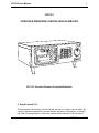


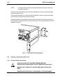
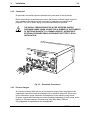

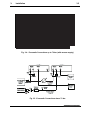

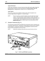
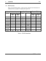
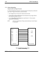
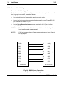
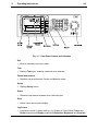

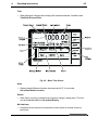
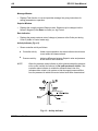
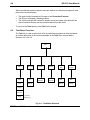
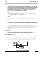
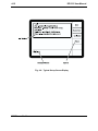
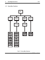


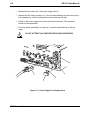
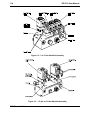
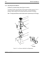
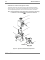


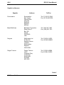
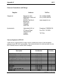
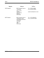
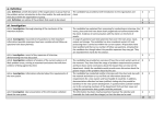

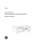


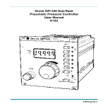


![RC400G Residual Chlorine Analyzer [Style: S3]](http://vs1.manualzilla.com/store/data/005893183_1-484cd185856d4428f9cc01b01a19e45f-150x150.png)