1
Pressure measurement
for research & industry
Druck Limited
Fir Tree Lane
Groby
Leicester LE6 0FH
England
Tel: 0116 231 7100
DPI 515
Precision Pressure
Controller/Calibrator
User Manual
K245
© Druck Limited 2005
This document is the property of Druck Limited and may not, either in part or whole, be copied or otherwise
reproduced, communicated in any way to third parties, nor stored in any data processing system, without the
express written authority of Druck Limited.
Page 1 of 114
K245 Issue No. 3
Do Not Print This Page
Amendment Record
Iss No
Date
C/N No
Originator
Typed
Amendments
1
10/0101/99
-
CER
CER
New specification
2
08/06/00
10639
CER
CER
No details recorded on amendment sheet
3
10/06/05
12648
13826
17261
BL
BL
Software up-issue to release 5.0
Addition of volume fill menu options
Manual completely revised to GE format.
Approvals
Engineering
Marketing
Publications
Phil Bradley
Julian Williams
Paul Stephens
Date:
Date:
Date:
Engineering
Harbi Mankia
Date:
Page 2 of 114
K245 Issue No. 3
Do Not Print This Page
Print Instructions
Print black on white, double sided as supplied on disk.
Print on paper to 110 gsm, Silverblade matt art, wiro bind in 270 gsm covers.
Size 180 x 230 mm.
THIS PUBLICATION IS PRINTED EXTERNALLY, THIS HARDCOPY IS NOT TO BE USED AS
CAMERA COPY.
Page 3 of 114
K245 Issue No. 3
Do Not Print This Page
Page 4 of 114
K245 Issue No. 3
Do Not Print This Page
GE Infrastructure
Sensing
Druck DPI 515
Precision Pressure Controller/Calibrator
User manual K245
English
1-1
to
6-26
Français
KF245.pdf
Deutsch
KD245.pdf
Italiano
KI245.pdf
Español
KE245.pdf
Português
KP245.pdf
© The General Electric Company. All rights reserved
Introduction
This technical manual provides operating instructions for the Druck DPI 515
Precision Pressure Controller/Calibrator.
Safety
The manufacturer has designed this equipment to be safe when operated using the
procedures detailed in this manual. Do not use this equipment for any other
purpose than that stated.
This publication contains operating and safety instructions that must be followed to
ensure safe operation and to maintain the equipment in a safe condition. The safety
instructions are either warnings or cautions issued to protect the user and the
equipment from injury or damage.
Use suitably qualified * technicians and good engineering practice for all procedures
in this publication.
Pressure
Do not apply pressures greater than the safe working pressure to the equipment.
Toxic Materials
There are no known toxic materials used in construction of this equipment.
Maintenance
The equipment must be maintained using the procedures in this publication. Further
manufacturer’s procedures should be carried out by authorized service agents or the
manufacturer’s service departments.
Technical Advice
For technical advice contact the manufacturer.
* A qualified technician must have the necessary technical knowledge,
documentation, special test equipment and tools to carry out the required work on
this equipment.
This equipment meets the requirements of all relevant European safety
directives. The equipment carries the CE mark.
When disposing of this equipment, consider the re-use of the following major
materials:
•
•
•
Sheet metal case parts:
Front panel, rotary control, rack handles:
Manifolds to 70 bar (1000 psi):
i
steel
ABS
Aluminium 6082
Abbreviations
The following abbreviations are used in this manual; the abbreviations are the same in
the singular and plural.
abs
Absolute
ABS
Acrylonitrile butadiene styrene
a.c.
Alternating current
ALT
Altitude
BSP
British pipe thread
CAS
Calibrated airspeed
CSK
Countersunk
d.c.
Direct current
DPI
Digital Pressure Instrument
e.g.
For example
etc.
And so on
Fig.
Figure
ft
Foot
g
Gauge
Hg
Mercury
HTS
High tensile steel
Hz
Hertz
IAS
Indicated airspeed
i.e.
That is
IEC
International Electrotechnical Commission
IEEE 488
Institute of Electrical and Electronic Engineers standard 488 data
in
Inch
kg
Kilogram
kts
knot
LCD
Liquid crystal display
m
Metre
mA
Milliampere
max
Maximum
mbar
Millibar
min
Minute or minimum
mm
Millimetre
mV
Millivolts
No.
Number
NPT
National Pipe Thread
Para.
Paragraph
PDCR
Pressure transducer
Ps
Static pressure
psi
Pounds per square inch
Pt
Total pressure (Pitot)
PTX
Pressure transmitter
ii
Abbreviations (continued)
Qc
QFE
QNH
ROC
RS232
SCM
SCPI
UUT
V
+ve
-ve
°C
Differential pressure Ps/Pt
Local atmospheric pressure
Barometric pressure at sea level
Rate of climb
Serial communications data standard
Sensor Conditioning Module
Standard Commands for Programmable Instruments
Unit under test
Volts
Positive
Negative
Degrees Celsius
Associated publications
Druck publication
K257 SCPI User Manual
K283 DPI 515 Calibration Manual
Symbols
The equipment contains the following symbols to identify hazards.
This symbol, on the equipment, indicates that the user must refer to the user
manual. This symbol, in this manual, indicates a hazard to the user.
This symbol, in the equipment, identifies static sensitive components, handle
with extreme care.
iii
Pressure units and conversion factors
Pressure unit
Factor (Pascal)
Pressure unit
Factor (Pascal)
bar
100000
lbf/ft2
47.8803
lbf/in2 (psi)
6894.76
inHg
3386.39
mH2O
9806.65
inH2O [1]
249.089
mbar
100
ftH2O [1]
2989.07
kgf/cm2
98066.5
atm
1013525.0
kgf/m2
9.80665
kgf/cm2
98066.5
mmHg
133.322
kgf/m2
9.80665
cmHg
1333.22
hbar
10000000
mHg
133322.0
tonf/ft2 (UK)
107252.0
mmH2O [1]
9.80665
tonf/in2 (UK)
15444300
mH2O [1]
98.0665
inH2O (USA) [2]
248.64135
N/m2
1
ftH2O (USA) [2]
2983.6983
hPa
100
kP/mm2
9806650
kPa
1000
kP/cm2
98066.5
MPa
1000000
kP/m2
9.80665
torr
133.322
Unit Conversion
To convert FROM pressure VALUE 1 in pressure UNITS 1
TO pressure VALUE 2 in pressure UNITS 2, calculate as follows:
VALUE 2
=
VALUE 1 x FACTOR 1
FACTOR 2
Note
The conversion factor for pressure units referenced [1] are calculated for a water
temperature of 4°C. Pressure units referenced [2] are calculated for a water
temperature of 68°F these units are normally used in the USA.
iv
CONTENTS
Section
Title
Page
1
DESCRIPTION……..........…………………………………………….
1-1
1.1
Introduction………………………………………………………………
1-1
2
INSTALLATION..............................…………………………………...
2-1
2.1
Packaging.........…………………………………………………………
2-1
2.2
Packaging for Storage or Transportation……………………………
2-1
2.3
Preparation for use...…………………………………………………...
2-1
2.4
Pneumatic connections…………………………………………….….
2-2
2.5
Rack-mounting................………………………………………………
2-6
2.6
Electrical connections……………….…………………………………
2-7
2.7
RS232 Interface..............………………………………………………
2-10
2.8
IEEE 488 Interface..........………………………………………………
2-13
2.9
Aeronautical Option..........……………………………………………
2-15
2.10
Sensor Conditioning Module Option…………………………………
2-17
3
OPERATION………………………………………………………...…
3-1
3.1
Preparation………………………………………………………………
3-1
3.2
Quick Reference……………………………………………………….
3-2
3.3
First Time Operators……………………………………………………
3-3
3.4
Operation and Example Procedures………………………………….
3-9
3.5
Set-up Selections……………………………………………………
3-22
3.6
Aeronautical Option…………………………………………………
3-25
3.7
Sensor Conditioning Module Option………………………………...
3-32
v
4
MAINTENANCE…………………………………………………………
4-1
4.1
Introduction……………………………………………………………..
4-1
4.2
Visual Inspection.................………………………………………….
4-1
4.3
Cleaning.....................………………………………………………..
4-1
4.4
Calibration.....................……………………………………………...
4-1
4.5
Replacement Parts……………………………………………………
4-2
4.6
Fuse Replacement……………………………………………………..
4-3
4.7
Valve Replacement...............………………………………………….
4-4
4.8
Valve Correction.............................................................................
4-11
5
TESTING AND FAULT FINDING………………………..…………….
5-1
5.1
Introduction…...........................………………………………………
5-1
5.2
Standard Serviceability Test……………………………………………
5-1
5.3
Fault Finding.......…………………………………………………….….
5-3
5.4
Approved Service Agents……………………………………………...
5-4
6
REFERENCE AND SPECIFICATION………………………………...
6-1
6.1
Installation notes.…………………………………………………….....
6-1
6.2
Operational Requirements……………………………………………..
6-3
6.3
Basic Task............…………………………………………………..….
6-5
6.4
Valve Assembly Description……………………………………………
6-6
6.5
User Set-up.....……………………………………………………….…
6-7
6.6
Supervisor Set-up...........………………………………………….…..
6-9
6.7
Communications - Instrument Emulation.…………………………….
6-16
6.8
Specification................………………………………………...……....
6-18
6.9
Return Goods/Material Procedure..................................................
6-23
6.10
Ancillary Equipment.........................................................................
6-25
vi
Druck DPI 515 Precision Pressure Controller/Calibrator User Manual
1
Description
1.1
Introduction
The Druck DPI 515 Precision Pressure Controller/Calibrator measures and controls
pneumatic pressure and displays, on an LCD screen, the pressure measurement and
controller status. A key-pad next to the display enables manual selections and settings in
both measure and control modes. The instrument can be operated remotely through serial
or parallel communication interfaces. The instrument can contain one or two pneumatic
measure/control channels of different pressure ranges.
Figure 1-1 DPI 515 General view
The rear panel houses the electrical and pneumatic output and input connections. Each
pneumatic channel (up to 70 bar (1000 psi) maximum) contains a positive and negative
pressure supply port, an outlet port, vent port and reference port. The electrical
connections provide an a.c. power supply, serial and parallel communication interfaces, d.c.
output and logic input and output.
Note: Two connectors identified as instrument bus are for factory use only.
The Druck DPI 515 can be used as a benchtop instrument or for mounting in a standard 19
inch rack system by using the rack mounting kit (option D) to adapt the instrument case.
K245 Issue No. 3
1-1
1 Description
The Druck DPI 515 uses the SCPI (Standard Commands for Programmable Instruments)
communication protocol enabling a standardised communication codes with other
instruments. Additionally, emulation-supported command codes enable operation with
other GE products: Druck DPI 500, DPI 510 and DPI 520 controllers and the Ruska 7000
controller.
Options add to the abilities of the Druck DPI 515 these include a barometric reference,
negative calibration to minus 1 bar (15 psi), enhanced absolute pressure performance and
aeronautical units.
Further information and notes on applications are available on the Druck web site at
www.gesensing.com and www.DPI515.com.
K245 Issue No. 3
1-2
Druck DPI 515 Precision Pressure Controller/Calibrator User Manual
2
Installation
2.1
Packaging
On receipt of the instrument check the contents of the packaging against the following list:
Packaging List
i)
DPI 515 Pressure Controller/Calibrator.
ii)
Power supply cable.
iii)
User manual (this publication).
iv)
Silencer (for each VENT port).
v)
Calibration certificate.
2.2
Packaging for Storage or Transportation
To store the instrument or to return the instrument for calibration or repair as follows:
1.
Pack the instrument as detailed in section 6.9, Reference and Specification.
2.
To return the instrument complete the return goods/materials procedure detailed in section
6.8, Reference and Specification.
2.3
Preparation for use
Note: Before operation, remove protective film from the display.
The instrument can be used as a:
•
Free standing instrument positioned on a horizontal surface.
•
Rack-mounted in a standard 19 inch rack using the rack-mount accessory kit.
For free standing instruments, use the two feet on the base to elevate the instrument to
provide a better viewing angle.
To rack-mount the DPI 515 instrument requires the rack-mount accessory kit, refer to
section 2.5.
K245 Issue No. 3
2-1
2 Installation
2.4 Pneumatic connections
WARNINGS:
TURN OFF THE SOURCE PRESSURE AND VENT THE PRESSURE LINES BEFORE
DISCONNECTING OR CONNECTING THE PRESSURE LINES. PROCEED WITH CARE.
ONLY USE EQUIPMENT WITH THE CORRECT PRESSURE RATING.
BEFORE APPLYING PRESSURE, EXAMINE ALL FITTINGS AND EQUIPMENT FOR
DAMAGE. REPLACE ALL DAMAGED FITTINGS AND EQUIPMENT. DO NOT USE ANY
DAMAGED FITTINGS OR EQUIPMENT.
THE SUPPLY- CONNECTION DISCHARGES FULL SYSTEM PRESSURE, ON HIGH
PRESSURE UNITS THIS DISCHARGE CAN CAUSE PHSYICAL INJURY. FIT THE
SILENCER SUPPLIED OR AN EQUIVALENT COMPONENT TO DIFFUSE THE
DISCHARGE.
Connection
USA only
Input
supply +
1/8 BSP
1/8 NPT
supply 1/8 BSP
1/8 NPT
Output
1/8 BSP
1/8 NPT
Vent
1/8 BSP
1/8 NPT
Reference
M5
M5
Pressure supply (Figure 2-1)
1.
The pressure supply must be clean, dry gas, nitrogen or air and at the correct pressure refer
to the specification (Section 6).
2.
Make sure that the user systems can be isolated and vented.
3.
Connect pressure and vacuum supplies to the SUPPLY + and SUPPLY - connection ports.
4.
Connect the Unit Under Test (UUT) to the required outlet connection port.
Figure 2-1, Pneumatic Connections
K245 Issue No. 3
2-2
Druck DPI 515 Precision Pressure Controller/Calibrator User Manual
Each pressure range of the instrument requires a positive pressure supply. Instruments
operating in an absolute range or negative pressure range require a vacuum supply. A
vacuum supply should also be used for a fast response for instruments operating near
atmospheric pressure.
Supply equipment
Pneumatic supplies should have isolation valves and, where necessary, conditioning
equipment. Each positive pressure supply should be regulated at 110% of the pressure
range stated on the pressure supply label. An instrument using a negative supply must be
enabled in the set-up menu.
On instruments without a negative supply, the positive pressure discharges from the system
to atmosphere through the negative supply port. A silencer can be fitted to the negative
port to reduce airflow noise.
Pneumatic Connection Examples (Figures 2-2, 2-3 and 2-4)
These examples show a dual range instrument; for a single range instrument use range 1
connections. Option G contains the in-line filters F1 and F2.
Figure 2-2, Pneumatic Connections up to 70 bar (1000 psi) (without vacuum supply)
Note:
K245 Issue No. 3
CONNECTED RANGES must be enabled when connecting the outlet ports
together. This applies to instrument ranges of 70 bar (1000 psi) and below.
Enabled in SETUP/SUPERVISOR/SYSTEM/CONNECTED RANGES.
2-3
2 Installation
Figure 2-3, Pneumatic Connections up to 70 bar (1000 psi) (with vacuum supply)
Notes:
1.
Option G includes in-line filters F1 and F2.
2.
Refer to section 6, Reference and Specification for details of other system components.
K245 Issue No. 3
2-4
Druck DPI 515 Precision Pressure Controller/Calibrator User Manual
Silencer
(if no vac)
Fit silencer
(system pressure vent)
VAC ON
2
Figure 2-4, Pneumatic Connections above 70 bar (1000 psi)
The positive pressure supply needs to be regulated for each range. The supply pressure
should be 110% of the pressure range. The pressure range supply rating label on the rear
panel gives the required pressure supply value. Refer to Section 6, Reference and
Specification for the recommended regulators.
When connecting a number of instruments of differing ranges to a common pressure
supply, appropriate external pressure regulators must be fitted in each instrument supply
line.
Note:
K245 Issue No. 3
Instruments with a range above 100 bar (1450 psi) must not have outlet ports
connect together.
2-5
2 Installation
2.5 Rack-mounting (Figure 2-5)
General
There must be enough space at the rear of the instrument for all the cables and pipes. The
length of the cables and pipes must allow for the removal and fitment of the instrument.
The cooling air outlet at the top left-hand corner of the rear panel of the instrument must not
be covered or obstructed. Allow a free flow of air around the instrument, especially at high
ambient temperatures.
Figure 2-5 Rack-mounting
Procedure
•
Slide the two support arms into the slots either side of the rear panel.
•
Locate the two handle brackets on the side of the instrument and secure with the two
screws and washers.
•
Support the instrument and connect the cables and pipes. Locate and slide the
instrument into the rack.
•
Secure the instrument in the rack.
•
Secure the two rear support arms to the rear tappings of the rack.
K245 Issue No. 3
2-6
Druck DPI 515 Precision Pressure Controller/Calibrator User Manual
2.6
Electrical connections
WARNINGS
1.
THE GROUND LEAD (GREEN/YELLOW) OF THE INSTRUMENT MUST BE
CONNECTED TO THE AC SUPPLY PROTECTIVE SAFETY GROUND.
2.
ISOLATE THE POWER SUPPLY BEFORE MAKING ANY ELECTRICAL
CONNECTIONS TO THE REAR PANEL.
3.
ISOLATE THE POWER SUPPLY BEFORE REMOVING THE INSTRUMENT’S
COVERS.
General
The instrument must be connected to the correct electrical power supply as stated on a
label next to the power connector. See section 6 Reference and Specification.
Make sure that the power supply is off before connecting the power cable.
Requirements for rack-mounted instruments
•
Install an isolator in the power supply circuit. The power supply connector and switch
on the rear panel of the instrument will not be accessible.
•
Set the power supply isolator to OFF. Connect the power supply and set the power
supply switch to ON before sliding the instrument into the rack.
Connecting (Figure 2-6)
To connect the power supply to the instrument proceed as follows:
•
•
•
Insert the moulded IEC connector (1) into the power supply assembly (5).
Set the ON/OFF switch (4) to ON (for rack-mounted instruments set the power supply
isolator to ON).
Check that the front panel display shows the power-up sequence.
K245 Issue No. 3
2-7
2 Installation
6
7
8
1
IEC power connector
5
Power supply assembly
2
Fuse carrier
6
24 V dc output
3
Fuse
7
Logic input
4
ON/OFF switch
8
Logic output
Figure 2-6 Electrical connections
24V DC Output
Using a 2-way connector:
pin 1 +24 Vdc
pin 2 frame
This facility can energise external equipment. An integral self-resetting fuse protects this
output.
Logic (switch) Input
Using a 2-way connector:
pin 1 +5 Vdc
pin 2 +24 Vdc
This facility can be used to trigger the instrument from a pressure switch contact during the
Pressure Switch Task (see Section 3.4). Integral opto-isolators protect this input circuit.
K245 Issue No. 3
2-8
Druck DPI 515 Precision Pressure Controller/Calibrator User Manual
Logic Outputs
Using a 3-way connector 1_2_3: pin 1 output, pin 2 common, pin 3 output.
Pin 1 and 3 volt-free contacts of relays RL1 and RL2.
Example connections
Note:
Between each set of contacts, a resistor/capacitor filter circuit restricts the upper
operating frequency, see Section 6 Reference and Specification.
Computer Connections
Fit the appropriate connectors into the rear panel communications port and secure with the
captive screws.
Note:
Only one interface can operate at a time. Set the required communications type
in SETUP/SUPERVISOR/COMMS/PORT menu, see Section 6.6.
RS232
IEEE 488
Figure 2-7, RS232 and IEEE 488 Connections
K245 Issue No. 3
2-9
2 Installation
2.7
RS232 Interface
When using the RS232 interface, a cable must be connected directly from the instrument to
a suitable port on the computer in a ‘point to point’ link. Table 2-1 shows the pin connections
for the 9-pin D-type, RS232 connector, the RS232 control signals, and the computer/printer
interconnection. The instrument is configured as Data Circuit Terminating Equipment (DCE).
Table 2-1, RS232 Connections
K245 Issue No. 3
2 - 10
Druck DPI 515 Precision Pressure Controller/Calibrator User Manual
Software Handshaking
Note:
Use software handshaking as the only recommended communications method.
For software handshaking between the instrument and a computer (or printer) that uses a 9pin, D-type port connection, proceed as follows:
•
•
•
Use a straight 9-way to 9-way male to female connector cable.
Connect the cable between the computer communications port and the instrument’s
9-way, D-type, RS232 port connector as shown in Figure 2-8.
Use the Set-up/Supervisor/Comms menu (see Section 6.6) to set-up the required
RS232 parameters.
Note:
Use a 9-way to 25-way adaptor for a computer with 25-way communications
port.
Figure 2-8, RS232 9-way connections (Software Handshaking)
K245 Issue No. 3
2 - 11
2 Installation
Hardware Handshaking
Note:
Only use hardware handshaking when necessary. Use software handshaking as
the only recommended communications method.
For hardware handshaking between the instrument and a computer that uses a 9-pin, Dtype port connection, proceed as follows:
•
•
•
Use a straight 9-way to 9-way male to female connector cable.
Connect the cable between the computer communications port and the instrument’s
9-way, D-type, RS232 port connector as shown in Figure 2-9.
Use the Set-up/Supervisor/Comms menu (see Section 6.6) to set-up the required
RS232 parameters.
Note:
Use a 9-way to 25-way adaptor for a computer with 25-way communications
port
.
Figure 2-9, RS232 9-way Connections (Hardware Handshaking)
K245 Issue No. 3
2 - 12
Druck DPI 515 Precision Pressure Controller/Calibrator User Manual
2.8
IEEE 488 Interface (Figure 2-10)
This interface complies with IEEE 488.2 HS standard. The IEEE 488 parallel interface
connects a computer/controller to one or more DPI 515 instruments and possibly other
instruments. Up to 30 instruments can be connected through a high-speed data bus to the
computer/controller.
To connect up the IEEE 488 interface, proceed as follows.
Note:
The length of each IEEE 488 cable must be less than 3 metres to comply with the
EMC requirements, see Section 6 Reference and Specification.
Single Unit Installation (Fig 2-10)
Connect an IEEE 488 connector/cable assembly to the rear panel IEEE 488 connector of the
instrument.
•
•
Connect the other end of the connector/cable assembly to the IEEE 488 connector on
the controller/computer.
Change the IEEE 488 communication parameters as described in the Set-up (Comms)
Menu (refer to Section 6.6).
Multiple Unit Installation (Figure 2-10)
To install multiple units use stacking plugs to link from first instrument to the second
instrument.
Proceed as follows.
•
1
2
3
•
•
•
Connect a pair of IEEE 488 stacking
connectors to the rear panel IEEE 488
connector of the instrument.
Connector to rear panel of first
instrument.
Connector from controller/computer.
Connector to rear panel of second
instrument.
Connect the other end of one of the
connectors to the IEEE 488 connector
on the controller/computer and the
other connector into the next
instrument.
Repeat this procedure for all the instruments in the system.
Use the Set-up (Comms) menu on each instrument to set up the required
communication parameters (Refer to Section 6.6).
K245 Issue No. 3
2 - 13
1
2
3
2 Installation
Figure 2-10 - IEEE 488 Connection
K245 Issue No. 3
2 - 14
Druck DPI 515 Precision Pressure Controller/Calibrator User Manual
2.9
Aeronautical Option.
Figure 2-11, Altimeter Checks (Typical Pressure Range 35-1310 mbar abs 1.0-38.68 inHg)
Figure 2-12, Check Airspeed Indicator or MACH meter
Notes:
1.
Select Go To Ground to ensure zero pressure before connecting the ASI or Mach meter.
2.
Reference port on Range 1 is common for Range 1 and 2 manifolds
K245 Issue No. 3
2 - 15
2 Installation
Static (Altitude)
Range 2
1310 mbar (38.68inHg) abs
Range 1
SUPPLY
+
OUTLET
Pitot
VENT
-
SUPPLY
+
OUTLET
Range 2
2 bar (30 psi)
Range 1
VENT
SUPPLY
-
+
REF
OUTLET
VENT
-
SUPPLY
+
OUTLET
VENT
-
REF
P
ALT
ASI
S
S
7 bar g
(100 psi g)
550 mbar g
(16.2 inHg g)
2.25 bar g
(33 psi g)
-1 bar
(-15 psi)
Figure 2-13, Example Connection of Two Instruments for Airspeed and Altimeter Testing
Notes:
1.
Good control can only be establish with the correct source supply pressure. High source
pressure can cause violent jumps in the output pressure that can damage rate-sensitive
equipment connected to the system. Low source pressure can cause poor stability of
the output pressure and may not meet control specifications for accuracy.
2.
When not testing an altimeter, the reference port can be opened to atmospheric
pressure, ASI calibration checks can be done relative to atmospheric pressure.
3.
When ASI calibration checks require an altitude above atmospheric pressure, use a
shut-off valve to isolate the port or blank off the altimeter test port (or connect a
serviceable altimeter) to enable control of static pressure.
i
The reference port is active for all ranges via the connection on range 1 of the
instrument only.
ii
The reference port of range 2 is blanked off and unused.
4.
When only testing altimeters, use a shut-off valve to isolate the port or blank off the ASI
test port (or connect a serviceable ASI).
K245 Issue No. 3
2 - 16
Druck DPI 515 Precision Pressure Controller/Calibrator User Manual
2.10 Sensor Calibration Module
The following details the test configurations for amplified output transducers, millivolt
output transducers and multiple transducer/transmitter testing. A rear panel, 15-way DType connector provides the outputs/inputs comprising two regulated power supply
outputs, 24V for current loop applications, a protected extension of the internal 24V supply
and a regulated 10V dc supply for the excitation of external transducers. Internally, the
instrument has a return line resistance of 0.15 W. The SCM can supply a maximum current
of 200 mA, this limits the maximum number of sensors that can be supplied in parallel.
The SCM option contains a set of test leads, see the connection details below.
D-type pin no.
Notes:
1.
2.
Cable colour
Cable function
Connector colour
1
Blue
+24V OUT
Blue
2
Yellow
+10V OUT
Yellow
3
Green
0V OUT
Green
4
Brown
11V+ IN
Red
5
Brown
11V- IN
Black
6
Violet
135 mV+
Red
7
Violet
135 mV-
Black
8
White
25 mA+ IN
Red
9
White
25 mA- IN
Black
10 to 15
Not used
-
-
The ends of the test lead terminate in standard 4mm plugs and a pair of test
probes (one red, one black), enables connection to the units under test.
Allow at least 2 minutes after applying power to the unit under test before taking
readings. Readings taken before the 2 minutes warm-up will be inaccurate.
Alternatively, arrange for continuous power to the unit under test.
K245 Issue No. 3
2 - 17
2 Installation
Single Pressure Transmitter (Figure 2-14)
Connect the cable of the transmitter to the SCM interface. Connect the pressure port of the
transmitter directly to the outlet port of the instrument.
Figure 2-14, Single Pressure Transmitter Test Set-up
K245 Issue No. 3
2 - 18
Druck DPI 515 Precision Pressure Controller/Calibrator User Manual
Multiple Pressure Transmitter Testing (Figure 2-15)
Connect each transmitter to the pressure manifold. Connect the inlet port of the pressure
manifold directly to the outlet port of the instrument.
At each applied pressure, switch, in turn, each transmitter into the current loop (either
manual or automatic multiplexing).
Figure 2-15, Multiple Pressure Transmitter Test Set-up
Note:
The 4mm test plugs can be connected together by inserting the pin of one into the end of
another. To link pins 3 and 9, insert the black connector (connected to the white lead labelled
25mA - IN), into the Green 0V connector.
K245 Issue No. 3
2 - 19
2 Installation
3-wire and 4-wire, Amplified Output Pressure Transducers (Figures 2-16 and 2-17)
Figure 2-16, 3-wire, Amplified Voltage, Pressure Transducer Test Set-up
Figure 2-17, 4-wire, Amplified Voltage, Pressure Transducer Test Set-up
K245 Issue No. 3
2 - 20
Druck DPI 515 Precision Pressure Controller/Calibrator User Manual
Figure 2-18, Multiple Pressure Transducer Test Set-up
K245 Issue No. 3
2 - 21
2 Installation
Figure 2-19, Millivolt Output Pressure Transducer Test Set-up (Compensated)
Note:
Using the regulated 10V supply compensates the transducer output for variations
in the supply.
Figure 2-20, Millivolt Output Pressure Transducer Test Set-up
Note:
When using an external supply, the instrument cannot compensate for changes in
transducer output due to power supply variations.
K245 Issue No. 3
2 - 22
Druck DPI 515 Precision Pressure Controller/Calibrator User Manual
Figure 2-21, Multiple Millivolt Output Pressure Transducer Test Set-up
Note:
This configuration uses the SCM 135mV Supply Corrected range. The SCM 10V
regulated supply, connected in parallel, provides permanent excitation to all the
pressure transducers, preventing errors from cold measuring elements.
K245 Issue No. 3
2 - 23
2 Installation
intentionally left blank
K245 Issue No. 3
2 - 24
Druck DPI 515 Precision Pressure Controller/Calibrator User Manual
3
Operation
3.1
Preparation
Make sure the electrical cables and pneumatic pipes comply with the installation
requirements in Section 2.
Carry out the following before use:
•
If necessary, carry out the maintenance task detailed in Section 4.
•
For bench-top, single instrument operation carry out the following:
1.
Make sure the instrument power supply switch on the rear panel is set to OFF.
2.
Connect the instrument to the electrical supply, make sure the supply includes a
connection to a protective earth.
3.
Inspect the pneumatic hoses for damage, ingress of dirt and moisture.
Before use, the instrument should be tested, for first time users see section 3.3, for users
requiring more operating detail see section 3.4.
This section contains a quick reference chart detailing all the key-pad functions. Further
quick reference charts, at the end of this section, detail the set-up menu.
Review and become familiar with the whole procedure before starting a process on a
component or system.
K245 Issue No. 3
3-1
3 Operation
3.2
Quick Reference (Figure 3-1)
A brief description of key-pad functions and general display indications follows:
Key/selection/display
Function and comments
Pressure Window
(Task menu)
Displays state of the pressure outlet selected, e.g. Value, Measured Pressure,
Controlled Pressure, Changing Pressure and full-scale range.
Help Window
(Set-up menu)
Displays a Help facility explaining functions of soft keys and gives instructions for
setting parameters.
Message Window
Displays menu level and task in use.
Provides message line giving instructions for setting parameters or operation.
Soft keys
Select menu functions
Soft Boxes
Displays the functions of the associated soft key
Numeric Keys
Sets the value for a parameter.
Exit
Returns instrument to previous menu.
Task
Displays Task menu, enabling a new task to be selected.
Control and Measure
Switches instrument between Control and Measure modes.
Set-up
Displays Set-up menus.
Delete
Deletes the last entered character from value entry box.
Enter
Enters values set on screen display
Jog Control
Incremental control of display settings, e.g. set-point in control mode, Preset and
Divider set-points and Display parameters (Resolution, Brightness and Contrast).
Display
Shows task specific information such as, current, set-point, rate and test parameters.
When enabled, shows instrument activity indicator.
1
Display panel
2
Message window
3
Pressure/Help window
5
Soft keys
6
Key-pad
7
Jog control
4
Soft boxes
Figure 3-1, Instrument Controls and Indications
K245 Issue No. 3
3-2
Druck DPI 515 Precision Pressure Controller/Calibrator User Manual
3.3
First Time Operators
The following sequences of operation should be used by first time operators and by
operators that use the instrument occasionally. For regular operators, familiar with the
instrument, go to section 3.4.
Note:
The following sequence is an example, the values and selections displayed depend
on the range (s) and options enabled in the instrument. To control pressure, the outlet port
must be connected to a UUT or a blanking plug fitted. The UUT must be of the correct pressure
rating or the instrument set to limit the set-point value to a safe pressure.
Set the power supply to ON and the power-up routine starts:
(1)
The display first shows:
(2)
After a short time the display
shows the start of the power-up
sequence, the instrument carries
out a self-test. If the test finds a
fault, the display shows an error,
refer to section 5, Fault Finding
and Testing
(3)
After a successful self-test
sequence the system changes to
measure mode. The display changes to measured pressure, showing the
parameters selected in Set-up.
(4)
K245 Issue No. 3
The instrument is now ready for use.
3-3
1
Mode
2
Range
3
Message window
4
Pressure reading
3 Operation
Soft keys in measure mode
Key-pad
1
returns to measure mode
2
see 3.4, task selection
3
see below, control mode
4
see above, measure mode
5
see 3.5, set-up menu
6
removes last entered digit
7
sets numeric value
K245 Issue No. 3
3-4
Druck DPI 515 Precision Pressure Controller/Calibrator User Manual
Soft keys in controlled pressure mode
Press the control key and the instrument changes the soft keys to:
units selected in set-up menu
system venting
YES
MPa
NO
psi
Range 1
changing range
Range 2
changing range
Gauge/
Absolute
mbar
mmHg
set tare
set filter
Rate
mmH2O
set %
available
ranges
and options
SCM
Gauge
* 2bar g
Absolute
SCM
available
ranges
and options
see option menu
range change
*1.31 bara
Value
Max
rate
maximum rate - set at the-factory
returns to
measured pressure display
Rate:
*
K245 Issue No. 3
example pressure range
3-5
300.00
mbar/s
3 Operation
Indications in controlled pressure mode (example 1)
Status displays and
messages
Function and comments
Mode status:
Measured pressure Measure mode
Changing pressure Control mode with pressure changing to set-point.
Controlled pressure Control mode pressure at set-point.
AUTO
Displayed when autorange enabled.
Tare: 0.50000
Tare value set to 0.50000 and enabled selected by Process soft key.
Filter
Filter enabled, selected by Process soft key.
%
Per cent reading of full-scale or set span, selected by Process soft key.
Head: 10.0000 cm
Head value set to 10 cm, height difference between instrument and UUT
Runner
Pressure change in progress - enabled and disabled in Setup/User/Display
Wait indicator
Instrument stopped - performing internal function.
Message window
Displays Task function, with instructions for setting a parameter or an operation.
set-point: 120.59 bar
Set-point at value of 120.59 in current selected units; can be changed using the
numeric key-pad or jog control.
Rate: 30 bar/s
Rate at value of 30 bar/s in current selected units per second; can be changed using
the numeric key-pad or jog control.
Key to display
1
Status
2
Set-point value
3
Alarm indicator
4
Range
5
In controlled mode, no over
shoot or fast
6
Filter ON
7
Autorange
8
Wait indicator
9
Runner
10 Rate value
1
4
3
2
6
15
(( ))
14
7
13
8
12
11 Message window
12 Activity indicator
13 Head (pressure) value
11
10
14 Tare value
15 Pressure reading
K245 Issue No. 3
5
3-6
9
Druck DPI 515 Precision Pressure Controller/Calibrator User Manual
Indications in controlled pressure mode (example 2)
Status displays and
messages
Function and comments
Mode status:
Measured pressure Measure mode
Changing pressure Control mode with pressure changing to set-point.
Controlled pressure Control mode pressure at set-point.
AUTO
Displayed when autorange enabled.
Tare: 0.50000
Tare value set to 0.50000 and enabled selected by Process soft key.
Filter
Filter enabled, selected by Process soft key.
%
Per cent reading of full-scale or set span, selected by Process soft key.
Head: 3.9370 in
Head value set to 3.937 in, height difference between instrument and UUT
Runner
Pressure change in progress - enabled and disabled in Setup/User/Display
Wait indicator
Instrument stopped - performing internal function.
Message window
Displays Task function, with instructions for setting a parameter or an operation.
set-point: 14.053 psi
Set-point at value of 14.053 in current selected units; can be changed using the
numeric key-pad or jog control.
Rate: 0.20 psi/s
Rate at value of 0.20 psi/s in current selected units per second; can be changed
using the numeric key-pad or jog control.
Key to display
1
Status
2
Set-point value
3
Alarm indicator
4
Range
5
In controlled mode, no over
shoot or fast
6
Filter ON
7
Autorange
8
Wait indicator
9
Runner
10 Rate value
1
4
3
2
15 psi g
14.053
15
3.937
14
14.053
13
7
psi
psi/s
8
12
12 Activity indicator
11
14 Tare value
15 Pressure reading
K245 Issue No. 3
6
psi
(( ))
11 Message window
13 Head (pressure) value
5
3-7
10
9
3 Operation
Controlling to a new set-point
•
To change the set-point value, press the control key and, using the numeric keys or
jog control, set the new set-point value.
•
If necessary, use the delete key to remove the last digit in the set-point value display
field.
•
When the display shows the new set-point value press the control
key.
•
The display shows the pressure value changing as the instrument
controls to the new set-point, at the set rate of change.
•
The activity indicator shows the progress of the instrument
controlling within the rate of change limits.
CA
PA
IT
Status Indicator
Controller activity
CC
Pressure activity
PC
In-limits tolerance
Controller condition
Pressure condition
Note:
In normal controlled pressure conditions the status indicator
stays within the in-limits tolerance band. If the status indicator moves outside the in-limits
tolerance band this can be caused by either a leak in the system or a change in supply
pressure.
P
shows the difference between the current pressure reading and the set-point value.
this valve symbol shows the working effort of the apply and release valves. The higher the
pointer the more the work rate of the apply valve. The lower the pointer
work rate of the release valve.
the more the
Controlling to ambient/zero pressure
•
Use the numeric keys or jog control and set the new set-point value of ambient or zero
pressure.
•
When the display shows the new set-point value, press the control or enter key.
•
The display shows the pressure value changing as the instrument controls to the new
set-point, at the set rate of change.
•
When the display shows ambient or zero pressure, press the measure key to switch
off the controller and return to measure mode.
Note: The instrument stays in measure mode showing the pressure measured at the outlet port.
K245 Issue No. 3
3-8
Druck DPI 515 Precision Pressure Controller/Calibrator User Manual
3.4
Operation and Example Procedures
Introduction
Before operation, the instrument must be connected to the correct electrical and pneumatic
supplies as detailed in Section 2, Installation.
Switch the instrument ON and, after a short time, the display shows measured pressure
mode (except when regulator mode is selected) in the Basic Task screen.
A dual range instrument always starts in the higher pressure range.
Measure and Control Modes
The instrument operates in two modes, Measure or Control. Pressing the Measure key
selects Measure mode, the instrument works as a precision pressure indicator and shows
the pressure measured at the outlet port. Pressing the Control key selects Control mode,
the instrument works as a precision pressure controller and shows the controlled pressure
measured at the outlet port. Pressing the Task key enables various pre-determined
functions
Task key
The message window at the bottom of the screen shows Task:Select, prompting for a
selection of an option from one of the soft keys. When selected, e.g. Basic, the display
shows the soft key options for the task (Units, Vent, Range and Process) and the upper line
of the message window changes to display Task:Basic. The status window at the top of the
screen displays Measured Pressure.
K245 Issue No. 3
3-9
3 Operation
Basic Task Selections
BASIC
BASIC
Units
Units
mbar
bar
psi
mH20
kPa
Mpa
(Actual units displayed
selected in user set-up menu)
Vent
Vent
Yes
No
CAUTION:
Yes causes the vent valve to open and USE THIS FACILITY
pressure to equalize with atmospheric WITH CARE
Range
Range
0.3 barg
2.5 barg
36 barg
(Actual ranges displayed selected
at manufacture)
Process
Process
Tare
Tare
Reading
Filter
Gauge/
Absolute*
*Only available
with the
barometric option
Gauge/
Absolute
Gauge
Value
On/Off
Current displayed value applied as
tare value.
Entered value applied as tare value.
Turns the Tare process on or off.
Filter
Time Constant
Band
Enable/Disable
Gauge
0.3 barg
2.5 barg
35 barg
}
Sets and enables the
required filter characteristics
(Actual ranges displayed selected
at manufacture)
Absolute
Absolute
1.3 bara
36 bara
(Actual ranges displayed selected
at manufacture)
Rate*
Value
*Only available
in control mode.
Set rate value
Rate: 300.0 mbar/s
change using
numeric key-pad or
jog control
MAX
rate
maximum rate
controller may overshoot
set-point
K245 Issue No. 3
3 - 10
Druck DPI 515 Precision Pressure Controller/Calibrator User Manual
Basic task
To control pressure in the Basic Task proceed as follows.
(a)
(b)
(c)
(d)
(e)
(f)
Select the required pressure range and units of pressure measurement from the soft
boxes displayed.
Press the Control key. The display changes to show set-point and rate.
The message window shows Confirm/Change set-point, and press Control to start.
Press the Rate soft key. The display shows two options, Value and Max Rate.
Press Value and enter the required rate of pressure change on the key-pad, e.g. 0.1
bar/s (1.5 psi/s), and press Enter. The display returns to the control mode screen.
Use the key-pad to select the required set-point e.g. 1.5 bar (22 psi) and press Control.
The screen display changes as follows:
•
•
•
The status window changes to show Changing Pressure.
The runner icon (if enabled) activates.
The activity indicator (if enabled) displays the current pressure and controller
condition.
When the controller achieves the selected pressure set-point, the screen display changes as
follows:
•
The status window changes to Controlled Pressure.
•
The runner icon in a standing position.
•
The activity indicator shows the controlled pressure within the in-limits
tolerance.
Caution:
Using the vent function can damage rate-sensitive equipment connected to
this controller. Enter a set-point of ambient/zero pressure and use the
controller to reduce pressure before selecting VENT.
(g)
On completion of testing, press the Vent soft key to reduce the system pressure to
near atmospheric pressure. This feature should be used to reduce system pressure to
a safe value before disconnecting the Unit Under Test.
Notes:
1. The vent opens for approximately 5 to 10 seconds.
2. Always use the vent function before disconnecting pressure equipment from the outlet
port.
(h)
Press the measure key to switch off the controller.
K245 Issue No. 3
3 - 11
3 Operation
Aeronautical option
The aeronautical option is a specialised application of the DPI 515 instrument refer to 3.9.
Leak testing
This task applies a test pressure to an external system to find any leaks in a system
connected to the instrument. This task sets the test pressure, dwell time at the test pressure
and the leak test time.
Leak test menu structure
At the start of the test, the instrument applies a test pressure to the user system. A dwell
time allows the user system to stabilise.
CP
=
changing pressure
D
=
dwell time
lk
=
leak
P
=
pressure
T
=
time (seconds)
TT
=
test time (up to 9999 seconds)
The instrument changes to measured mode and then records the pressure change during
test time. On completion, the display shows the Start Pressure, End Pressure, Pressure
Change and Leak Rate.
K245 Issue No. 3
3 - 12
Druck DPI 515 Precision Pressure Controller/Calibrator User Manual
Divider
Select and set-up the divider task by pressing Task/Divider/Set-up. The set-up menu
defines pressure span and then divides the span into a number of equal test points (min 2,
max 25). Alternatively, using the Quick 10% selection the menu sets 10 equally-spaced test
points.
Divider menu structure
Select required Range, Units, Rate, etc. in Basic task. When Divider is then entered from the
Task menu, these test point pressures are displayed in the soft key boxes. By entering
control mode, the soft keys can be pressed to change to these test pressures (and
*controlled at the selected pressure). The jog control can be used to “nudge” the set-point,
jog resolution in SETUP/USER/JOG RESOLUTION.
1
P
=
K245 Issue No. 3
pressure
3
2
S
=
3 - 13
steps
4
R
=
range
3 Operation
Preset
The Preset function is similar to the Divider function except that, using Task/Preset/Setup,
individual set-point values can be defined for each soft box (maximum 25 set-points). The
jog control can be used to “nudge” the individual set-point values, jog resolution in SETUP/
USER/JOG RESOLUTION.
The set-up function displays a preset number, pressing the soft key for that number assigns
a pressure value to the key. After setting all the required preset pressures, enter control
mode and then press a soft key to change to the pressure assigned to that key (and
*controlled at the selected pressure).
1
2
3
4
3
1
4
3
4
2
P
K245 Issue No. 3
=
pressure
T
3 - 14
=
time
Druck DPI 515 Precision Pressure Controller/Calibrator User Manual
Switch test
This function automates the testing of pressure switch devices. Connect the pressure port of
the switch to be tested to the appropriate outlet port. Connect the switch contacts in series
with the 24V dc output and the Logic Input.
Note:
The potential-free logic input connections require a switching potential (24V max) to
be applied. If necessary, this can be an external d.c. source.
Set the switch test parameters in the Task/Switch Test /Set-up menu, including the test
range and test rate of change. Slower rates give more accurate results.
Note:
This facility uses the rate of change of pressure set in the Basic task.
After the test, the display shows the pressures at which the contacts open and close and the
switch hysteresis (the difference between the two switching pressures). Before
disconnecting the switch under test, press the Release soft key to release any residual
pressure.
Example Switch Test Connections
K245 Issue No. 3
3 - 15
3 Operation
Pressure Cycling
Programs the controller to apply low and high pressure values at a defined rate of pressure
change for a defined number of cycles. This facility exercises pressure gauges or similar
equipment before calibration or testing.
Set the pressure cycling parameters in Task/Pressure Cycling/Set-up.
•
Use the soft keys and numeric keys to set High, Low, Rate of pressure change and the
number of Cycles.
Run
•
When selected, the controller performs a pressure cycle routine using the range outlet
port and settings selected in the Basic task.
R
H
P
K245 Issue No. 3
=
=
=
rate of pressure change
high value set-point
pressure
3 - 16
L
N
=
=
low value set-point
number of cycles
Druck DPI 515 Precision Pressure Controller/Calibrator User Manual
Barometric Reference
The barometric reference option measures the barometric pressure at the reference port of
Range 1. It permits the controller to operate in either gauge or absolute mode. Select gauge
or absolute in Basic mode. The controller stops during a change between gauge and
absolute.
The barometric task only changes the barometric pressure units. Select the units available
on the soft keys for this option in the User set-up.
K245 Issue No. 3
3 - 17
3 Operation
Test Program
The test program task provides a facility for writing and executing test procedures.
Selecting a test program from the Task menu displays all the task programs currently stored,
together with the Run, Set-up and Step function keys.
Test Program screen
K245 Issue No. 3
3 - 18
Druck DPI 515 Precision Pressure Controller/Calibrator User Manual
Program
To start a test program, select the test program listed on the screen using the jog (rotary)
control and press the RUN key. When the program starts, a Stop legend replaces the Run
legend. Press the Stop key at any time to stop the test program. The Step function key
allows the selected program to be executed one step at a time.
•
•
•
•
•
To write a test program, press the Set-up soft key and select New.
To edit an existing program, press Edit.
Enter a name for the program using the text editor keys to select letter range and the
jog control to select the letter within the range. Use the right arrow key to move to the
next character position.
Press enter on completion.
The display shows the line instruction with insert and delete selections. Pressing insert
changes the display to a list of the available programming commands.
Table 3.1 - Test Program Commands
Command
Description
Command
Description
set-point
Allows set-point to be entered.
Text
Sets screen message.
Dwell
Specifies dwell time (seconds).
Beep
Beep on/off.
In Limits
Wait for In Limits condition.
Rate Value
Specifies controller rate.
Range
Specifies instrument range
Rate Max
Sets controller rate to maximum.
Zero
Output zeroed
Vent
Instructs instrument to vent.
Control
Selects Control mode.
Count
Used in a loop to count the
number of loop cycles.
Measure
Selects Measure mode.
I/P Logic
Specifies change of state for
external contacts as a halt
condition.
Goto
Used to set-up a loop. Enter
program line number to go to.
Settling
Used to specify overshoot
requirements.
Pause
Causes test program to pause
for user input (Resume)
Resolution
Sets display resolution.
Units
Selects required display units.
End
Program end command.
To select a command, use the jog control to highlight the command on the display and press
enter to write it into the program. Place the Range, Units, Rate, Settling and Resolution
commands at the start of the program this protects pressure-sensitive UUT.
When selected, certain commands require a value or selection to be set (e.g.) Range, Rate,
Text the display shows a screen prompt for the appropriate setting.
K245 Issue No. 3
3 - 19
3 Operation
Example Program
Note:
Changes to instrument settings made in a test program remain valid only for the test
program. The instrument reverts to the pre-test settings on completion.
Step
Command
Argument
Action
1
RANGE
2.5 BAR G
Select 2.5 mbar g range
2
UNITS
MBAR
Select units, mbar
3
RATE
100
Select rate, 100 mbar/min
4
RESOLUTION
5
Display resolution, 5 digits
6
SETTLING
ZERO
No overshoot
7
TEXT
Operator instruction, e.g.
“Connect UUT”
8
ZERO
9
SET-POINT
400
Set-point, 400 mbar
10
CONTROL
Controller ON
11
IN LIMITS
Wait for In Limits Condition
12
BEEP
ON
Beep on, approx. 1 sec
13
BEEP
OFF
14
MEASURE
Switch to Measure (controller off)
15
DWELL
30
Wait for 30 sec
16
set-point
800
Set-point, 800 mbar
17
CONTROL
Controller on
18
IN LIMITS
Wait for In Limits Condition
19
BEEP ON
Beep on (approx. 1sec)
20
BEEP OFF
21
MEASURE
Switch to Measure (controller off)
22
TEXT
Operator instruction, e.g.
(Wait for beep, record pressure)
23
DWELL
30
Wait for 30 sec
24
BEEP ON
Beep on, approx. 1 sec
25
BEEP OFF
26
TEXT
Operator instruction, e.g.
“Min pressure allowed 785 mbar”
26
PAUSE
WAIT,
(press Resume to continue)
27
VENT
Vent
28
END
Program end
K245 Issue No. 3
3 - 20
Druck DPI 515 Precision Pressure Controller/Calibrator User Manual
Programming Loops
To program a loop, use the Goto command. Include the Count command in the loop for
counting the number of loop cycles.
Note:
The test program commands do not include tests for conditional jumps; to stop a test program
from looping, the Stop soft key must be pressed by the operator.
Example of programming a loop
1
RANGE
2.5 MBAR G
2
UNITS
MBAR
3
RATE
100
4
RESOLUTION
5
6
SETTLING
ZERO
7
TEXT
Operator instruction, e.g.
8
ZERO
9
SET-POINT
400
10
CONTROL
11
IN LIMITS
12
BEEP ON
13
BEEP OFF
14
MEASURE
15
DWELL
30
16
SET-POINT
800
17
CONTROL
18
IN LIMITS
19
BEEP ON
20
BEEP OFF
21
MEASURE
22
COUNT
23
VENT
24
GOTO
9
28
END
K245 Issue No. 3
3 - 21
Select 2.5 mbar g range
Select units, mbar
Select rate 100mbar/min
Display resolution 5 digits
No overshoot
“Connect UUT”
Set-point, 400 mbar
Controller ON
Wait for In-limits condition
Beep on, approx. 1 sec
Switch to measure (controller off)
Wait, 30 sec
Set-point, 800 mbar
Controller on
Wait for In-limits condition
Beep on, approx. 1sec
Switch to measure, controller off
Increment loop counter
Vent
Loop back to program line 9
Program end
3 Operation
3.5
Set-up Selections
Two set-up selections provide access to the instrument set-up menus, User and Supervisor.
The User set-up provides direct access by the operator with the Supervisor set-up accessed
only by a four digit PIN.
Press Set-up on the key-pad and the display shows four selections, User, Supervisor,
Calibration and Status next to the corresponding soft keys on the right of the display
screen.
1
Selections
2
Message window
3
Help window
The upper part of the screen shows the HELP window describing the sub-menus available in
these four selections. The upper line of the message window shows the menu option in use.
Pressing the appropriate soft key selects the appropriate menu, when selected, e.g. User, the
display shows more selections in the soft boxes on the right of the screen and the message
window changes to show Set-up: User.
When selected, e.g. Units, the display shows selections in the soft boxes on the right of the
screen, the upper line of the message window changes to show Set-up: Units. A ‘message
line’ appears at the bottom of the message window prompting the user’s next action.
To return to the User selections, press Exit on the key-pad. To return to the Set-up menu,
press Exit twice or Set-up once.
The User Set-up menu provides facilities for programming frequently changed settings as
follows.
K245 Issue No. 3
3 - 22
Druck DPI 515 Precision Pressure Controller/Calibrator User Manual
K245 Issue No. 3
3 - 23
3 Operation
K245 Issue No. 3
3 - 24
Druck DPI 515 Precision Pressure Controller/Calibrator User Manual
3.6
Aeronautical Option
The Aeronautical task enables control and measurement of altitude and airspeed in
aeronautical units such as feet and metres (altitude) and knots, mph, km/h (airspeed). This
task utilises dual pressure displays to show the parameter and the rate of change of
Altitude, Airspeed, Mach and Airspeed with Mach number.
The Aeronautical Task enables the testing and calibration checking of aeronautical
indicators and system components by controlling and displaying values and rates in
aeronautical units.
The instrument automatically selects the appropriate pressure ranges for altitude and
airspeed (normally 1.3 bar (19.5 psi) absolute and 2.0 bar (30 psi) differential respectively).
Cautions:
1.
Do not exceed the maximum pressures stated in the appropriate Component
Maintenance Manual for the unit under test.
2.
Carefully de-pressurize all pipes to atmospheric pressure before disconnecting
and connecting to the unit under test.
Example of Two Instruments for Altitude and Airspeed Testing (Figure 2-13)
This example shows how two instruments can be used to simultaneously generate altitude
and airspeed.
Cautions:
1.
Before testing, set the rate of change for both DPI 515 Instruments to a safe value.
A high rate of change can damage sensitive aeronautical components. Refer to
the appropriate Component Maintenance Manual for the unit under test.
2.
In this example configuration, negative airspeed can be generated this can
damage an airspeed indicator. To prevent negative airspeed, apply the static
pressure before the pitot pressure for increasing and decreasing airspeed values.
K245 Issue No. 3
3 - 25
3 Operation
Aeronautical Task
Select the Aeronautical task from the Task menu. The display shows four menu items:
Mode
•
Press the mode soft-key to select an operating mode such as Altitude or Speed.
Units
•
The Units soft-key provides access to either the Aeronautical or Pressure units. At
any time, the units can be changed between pressure and pressure converted to
aeronautical units. The display shows the outlet pressure converted to Altitude, CAS or
Mach using BS 2G 199:1984* conversions and assuming standard atmospheric
conditions.
* Based on tables from ICAO Standard Atmosphere 1964.
Reference Pressure
•
Press this key to select the required reference pressure. This can be either the
barometric pressure (from the instrument’s internal barometric sensor), or any
numeric value (e.g.) 1013.25 mbar (29.92 inHg).
Go to ground
•
Press this key to return the instrument and any unit under test (UUT) connected to it
safely to ground pressure at a controlled (timed) rate.
K245 Issue No. 3
3 - 26
Druck DPI 515 Precision Pressure Controller/Calibrator User Manual
K245 Issue No. 3
3 - 27
3 Operation
Altitude Measure Mode
Press Mode and select Altitude from
the menu. The display shows Altitude
in the upper window and Rate of
climb in the lower window. Both
windows show the current value in
large characters.
The ROC type soft-key permits the
rate of climb display to be rapidly
updated (Instant) or to measure ROC
averaged over a pre-set time period
(Timed). The latter method results in
a lower noise reading
Altitude
FS=80000
288ft
Rate of climb
0
Mode
Go to
Ground
ROC
Type
ft/sec
Task: Aeronautical
Timed Rate: 60 S
Units
Altitude Control Mode
Press Mode and select Altitude from the menu. Press Control, the display shows the aim
value entry boxes together with the Set Altitude and Set ROC soft boxes.
Set Altitude
FS=80000
Altitude
Mode
•
Press this soft-key to highlight
Set
the Aim value entry box on the
Altitude
Altitude display. The numeric
ft
AIM: 1000
Go to
key-pad may be used to input
Rate of climb
Ground
the required Altitude. Press
ROC
ENTER to confirm.
Type
Set Rate of Climb (ROC)
Set
AIM: 50
ft/sec
•
Press this soft-key to highlight
ROC
the Aim value entry box on the
Task: Aeronautical
Timed Rate: 60 S
Units
ROC display. The numeric keypad may be used to input the
required ROC set-point. Press
ENTER to confirm.
ROC Type
•
Timed ROC can be used to produce an accurate measurement of ROC over specified
period (in seconds).
•
Instantaneous ROC shows the current ROC value on the display.
With the Aim Altitude and the ROC set, press Control again to start the change to the new
aim value.
Go to Ground
•
Pressing this soft-key option makes the instrument control the altitude to ZERO feet/
metres (@1013.25 mbar), at the currently set ROC for safe disconnection.
288
0
K245 Issue No. 3
3 - 28
Druck DPI 515 Precision Pressure Controller/Calibrator User Manual
CAS Measure Mode
Press Mode and select CAS from the
menu. The display shows CAS in the
upper window and rate of Speed
(acceleration) in the lower window.
Both windows show the current value
in large characters.
Calibrated Air Speed
FS=1000kts
Mode
0.0
kts
Rate of speed
Go to
Ground
0.0
kts/sec
Task: Aeronautical
Units
CAS Control Mode
Press Mode and select CAS from the
menu. Press Control, the display shows the aim value entry boxes together with the Set CAS
and Set Rate soft boxes.
Set CAS
•
Press this soft-key to highlight
FS=1000kts
Calibrated Air Speed
Mode
the Aim value entry box on the
Airspeed display. The numeric
Set
CAS
key-pad may be used to enter
AIM: 648.3
kts Go to
the required airspeed set-point.
Rate of speed
Ground
Press ENTER to confirm.
Set Rate
•
Press this soft-key to highlight
Set
kts/sec
AIM: 50
the Aim value entry box in the
Rate
Rate of Speed window. The
Task: Aeronautical
Units
numeric key-pad may be used
to enter the required Rate of
Speed set-point. Press ENTER
to confirm.
With the Aim CAS and the Rate set, press Control again to start the change to the CAS Aim.
Go to Ground
•
Pressing this soft-key option makes the instrument control the airspeed to ZERO for
safe disconnection of the Unit Under Test (UUT).
0.0
0.0
K245 Issue No. 3
3 - 29
3 Operation
Mach Measure Mode
Press Mode and select MACH from
the menu. The display shows Mach in
the upper window and Rate (Rate of
Mach, acceleration) in the lower
window. Both windows have a
current value display in large
characters. Only the Rate window
has a reference (Ref:) value in smaller
characters.
FS=5 Mach
Mach
0.0048
Mach
Rate
Ref: 1006.53
0.0016
Mach/s
mbar
Mode
Go to
Ground
Ref
Pressure
Task: Aeronautical
Mach Reference Pressure
The reference pressure can be set to
a fixed value for the static (Ps)
pressure.
•
The instrument then calculates
Mach number values based on
this reference pressure.
•
The static (Ps) connection can
remain open to atmosphere
pressure.
Mach Control Mode
•
•
•
Press Mode and select MACH
from the menu. Press Control
the display shows Mach in the
upper window and rate in the
lower window. Both windows
show the current value in large
characters.
Mach aim value entry box with
the Set Mach soft box.
Press this soft-key to highlight
the Aim value entry box in the
Mach window. The numeric
key-pad may then be used to
enter the required Mach aim.
Press ENTER to confirm.
K245 Issue No. 3
FS=5 Mach
Mach
0.0048
Mach
Barometer
Value
Rate
Ref: 1006.53
0.0016
Mach/s
mbar
Task: Aeronautical
FS=5 Mach
Mach
0.0048
Mach
AIM: 0.0000
Rate
Ref: 1006.53
Task: Aeronautical
3 - 30
0.0016
Mach/s
mbar
Mode
Set
Mach
Go to
Ground
Ref
Pressure
Druck DPI 515 Precision Pressure Controller/Calibrator User Manual
Set Mach
•
Press this soft-key to highlight the Aim value entry box. With the Mach Aim set, press
Control again to start the change to the Aim Mach.
Go to Ground
•
Pressing this soft-key option makes the instrument control the airspeed to ZERO (Mach
= 0), for safe disconnection.
CAS and Mach Measure Mode
This mode enables the testing of
combined speed indicators (CAS
Mach). Press Mode and select CAS
MACH from the menu. The display
shows.CAS in the upper window and
Mach in the lower window.
Go to Ground
•
Pressing this soft-key option
makes the instrument control
the airspeed to ZERO (Mach =
0), for safe disconnection.
Mach Reference Pressure
•
The reference pressure can be
set to a fixed value for the
static (Ps) pressure. The instrument then calculates CAS and Mach number values
based on this reference pressure.
CAS and Mach Control Mode
Press Mode and select CAS MACH
from the menu. Press Control and
the display shows the CAS aim value
entry box.
Set CAS
•
Press this soft-key to highlight
the Aim value entry box on the
Airspeed display. The numeric
key-pad may then be used to
enter the required CAS value.
Press ENTER to confirm.
With the Aim CAS and the Rate set,
press Control again to start the
change to the CAS Aim at a rate of
change set in CAS control mode.
Go to Ground
•
Pressing this soft-key option makes the instrument control the airspeed to ZERO (Mach
= 0).
K245 Issue No. 3
3 - 31
3 Operation
3.7
Sensor Calibration Module Option
The SCM option module provides an interface for the direct connection of a wide variety of
pressure transducers/transmitters. When connected, the DPI 515 instrument with the
supporting SCM software can be used to calibrate these devices.
K245 Issue No. 3
3 - 32
Druck DPI 515 Precision Pressure Controller/Calibrator User Manual
A rear panel, 15-way D-Type connector provides the outputs/inputs comprising two
regulated power supply outputs, 24V for current loop applications, a protected extension of
the internal 24V supply and a regulated 10V dc supply for the excitation of external
transducers, refer to Section 2 Installation.
SCM Option Task
Enter the SCM option from the Basic Task by selecting Range and one of the SCM test
options (135 mV, 135 mV Supply Corrected, 11V or 25mA) and proceed as follows:
1.
Press Range and select the required range for the UUT (e.g.) 2 bar g. Press Range
again, followed by SCM and then select the appropriate SCM function (e.g.) 25 mA.
Measured Pressure
FS = 2bar g
0.00035
bar
SCM Off
Measured Pressure
FS = 2bar g
0.00035
135 mV
Auto
Range
SCM
bar
135 mV
Supply
Corrected
2 bar g
11V
20 bar g
25 mA
Task: Basic
2.
Task: Basic
After selection of SCM function, the display
shows. the transmitter output. Press Control
to display set-point and Rate setting windows.
Measured Pressure
FS = 2bar g
0.00035
bar
Units
Vent
Range
Process
Current:
4.0004 mA
Task: Basic
3.
Set the required set-point, either by direct
entry from the key-pad, followed by Enter or
by rotating the Jog control, followed by Enter.
Rate
Measured Pressure
FS = 2bar g
0.00035
bar
Setpoint:
1.50000
Rate:
0.50000 bar/sec
Current:
4.0004 mA
Task: Basic
Confirm/change Setpoint, press Control to start
K245 Issue No. 3
3 - 33
Gauge/
Absolute
Units
Vent
Range
Process
Gauge/
Absolute
Rate
3 Operation
4.
Press the Rate key. Select the required rate of
change of pressure, either by direct entry from
the key-pad, followed by Enter or by rotating
the jog control followed by Enter.
Alternatively, select MAX for maximum rate of
change.
Measured Pressure
FS = 2bar g
0.00035
bar
Setpoint:
1.50000
Rate:
0.50000 bar/sec
Current:
Value
Max
Rate
4.0004 mA
Task: Basic
5.
Press Control to start the test. The display
shows the activity monitor and the instrument
controls the applied pressure to the set-point
at the preset rate.
Measured Pressure
FS = 2bar g
1.00750
bar
P
6.
At the end of testing enter a set-point of zero
(or ambient pressure) to safely return to
ground pressure at a controlled (timed) rate.
K245 Issue No. 3
3 - 34
Setpoint:
1.50000
Rate:
0.50000 bar/sec
Current:
Task: Basic
14.6668 mA
Units
Vent
Range
Process
Gauge/
Absolute
Rate
Druck DPI 515 Precision Pressure Controller/Calibrator User Manual
4
Maintenance
4.1
Introduction
This section contains the routine maintenance and procedures to replace components
detailed in Section 5, Testing and Fault Finding and listed in Table 4.2.
Table 4.1 - Maintenance Tasks
Task
Period
Visual Inspection
Daily, before use
Cleaning
Weekly*
Test
Before use
Calibration
12 months
* may change depends on usage (e.g., rack mounted, bench top) and environment (e.g., humidity,
dust).
4.2
Visual Inspection
Inspect the external of the instrument, and associated equipment, for obvious signs of
damage, dirt, and ingress of moisture. If necessary, clean the instrument as detailed below.
4.3
Cleaning
Clean the instrument every week. Clean the front panel with a damp lint-free cloth and mild
detergent.
Caution:
4.4
Do not use solvents for cleaning.
Calibration
The instrument should be withdrawn from service and returned to the manufacturer or
calibration facility.
To find the date of the last calibration, press SETUP/Status/Calibration history. Do not use an
instrument with out-of-date calibration.
K245 Issue No. 3
4-1
4 Maintenance
4.5
Replacement Parts
Use only the replacement parts listed in Table 4.2.
WARNING:
ISOLATE THE INSTRUMENT POWER SUPPLIES BEFORE REMOVING THE
COVERS, WITH POWER APPLIED THE INSTRUMENT CONTAINS LETHAL
VOLTAGES.
Caution:
This instrument contains static sensitive components, handle with
extreme care.
Table 4.2 - Replacement Parts List
Part
number
Description
-
Fuse T2.0A
176-066
Control Valve (0 to 10 bar) [0 to 150 psi]
176-067
Switching Valve (0 to 10 bar) [0 to 150 psi]
079-061
Bolts, M3 socket head, high tensile steel countersunk
176-065
Control Valve (>10 to 70 bar) [>150 to 1000 psi]
176-067
Switching Valve (>10 to 70 bar)[>150 to 1000 psi]
079-061
Bolts, M3 socket head, high tensile steel countersunk
176-072
Control Valve (70 to 210 bar) [1000 to 3000 psi]
-
Switching Valve (not fitted)
079-030
Bolts, M4 socket head, high tensile steel countersunk
K245 Issue No. 3
4-2
Druck DPI 515 Precision Pressure Controller/Calibrator User Manual
4.6
Fuse Replacement (Fig 4-1)
Replace the fuse when detailed in Section 5, Testing and Fault Finding:
•
Set the power switch (4) to OFF.
•
Isolate the power supply to the instrument and disconnect the IEC power supply
connector (1).
Note:
•
To gain access to rack-mounted instruments, it may be necessary to partially or
completely withdraw the instrument. Isolate pneumatic supplies and depressurise all pressure supply inlet and outlet lines.
Remove the fuse carrier (2) from the power supply input socket assembly (5) and
replace the fuse cartridge.
Note:
Fit the correct type of fuse detailed in Table 4-2.
•
Refit the fuse carrier (2) in the power supply inlet socket assembly (5).
•
Reconnect the IEC power supply connector (1). Refit and reconnect rack-mounted
units as detailed in Section 2 Installation.
•
Switch on the power supply and set the power supply switch to ON. The instrument
should now be operational.
•
If the fuse blows immediately on switch-on, contact the manufacturer or Service
Agent.
K245 Issue No. 3
4-3
4 Maintenance
6
7
8
1
IEC power supply connector
2
Fuse carrier
3
Fuse
4
Power supply switch
5
Power supply inlet socket assembly
Figure 4-1, Power Supply Fuse Replacement
4.7
Valve Replacement
Replace a valve when detailed in Section 5, Testing and Fault Finding:
Procedure
Full-scale pressures below 70 bar [1000 psi] (Figure 4-2 and 4-4)
A similar valve replacement procedure applies to all the valves located on this manifold:
Note: The Apply and Release control valves are a matched pair, do NOT replace single valves.
(a)
Disconnect the supply pressure and vent all pressure from the instrument.
(b)
Switch off the controller and isolate the power supply.
(c)
Remove the instrument top cover by removing the three securing screws from the top edge
of the rear panel, sliding the cover back and then up.
(d)
Identify the valve to be replaced from Figure 4-2.
(e)
Unscrew the valve solenoid locking ring (1) and remove the locking ring and the lock washer
(2). Lift the solenoid (3) clear of the valve body (5).
Note:
K245 Issue No. 3
There is no need to disconnect the electrical connections to the solenoid.
4-4
Druck DPI 515 Precision Pressure Controller/Calibrator User Manual
(f)
Remove the four, M3 socket head, high tensile steel countersunk bolts (9), securing the valve
body (5) to the manifold block (8) and lift the valve body clear of the manifold. Discard the
four, M3 socket head HTS CSK bolts (9).
Note:
Do not re-use the original M3 socket head HTS CSK bolts (9) and only use the
replacement parts listed in Table 4-2.
(g)
Wipe the surface of the manifold clean.
(h)
Ensure that the valve seating area on the manifold block is clean and place the new valve
body (5) into position over the fixing holes.
(i)
Insert the M3 socket head HTS CSK bolts (9) and initially, screw in finger tight.
(j)
Carefully torque tighten in sequence to 1.2 Nm (10.62 lbf in) the M3 socket head HTS
CSK bolts (9).
(k)
Unless the valve solenoid is faulty, refit the solenoid (3) over the valve body (5), replace the
lock washer (2) and tighten the locking ring (1).
Note:
If the spade terminal connectors (4) have become disconnected from the solenoid,
push the connectors back onto the solenoid terminals. The connections to each
valve are colour coded (see Figure 4.2).
(l)
Refit the top cover of the instrument and reconnect the power supply and the input and
output pneumatic supplies.
(m)
Switch on the instrument and carry out a leak test (see Section 3).
(n)
Carry out the valve correction procedure as detailed in Section 4.4.
K245 Issue No. 3
4-5
4 Maintenance
1
2
3
9
4
5
6
7
6
8
7
1
Solenoid locking ring
2
Washer
3
Solenoid
4
Terminal, spade
5
Valve body
6
O-ring
7
O-ring
8
Manifold
9
M3 socket head HTS CSK bolt
Figure 4-2, Low Pressure Manifold Valve Replacement
K245 Issue No. 3
4-6
Druck DPI 515 Precision Pressure Controller/Calibrator User Manual
4
5
6
3
7
2
1
8
9
10
1
Manifold
2
M3 socket head HTS CSK bolt
3
Zero valve assembly
4
Isolation valve assembly
5
Release control valve
6
Apply control valve
7
Brown cables
8
Red cables
9
Orange cables
10
Yellow cables
Figure 4-3, 0-70 bar (0-1000 psi) Manifold Assembly
K245 Issue No. 3
4-7
4 Maintenance
Procedure
Full-scale pressures from 70 to 210 bar [1000 to 3000 psi] (Figure 4-4 and 4-5)
The valve replacement procedure, which is the same for both valves, is as follows.
Note:
(a)
The Apply and Release control valves are a matched pair, do NOT replace single
valves.
Disconnect the supply pressure and vent all pressure from the instrument.
(b)
Switch off the controller and isolate the incoming power supply.
(c)
Remove the instrument top cover by removing the three securing screws from the top edge
of the rear panel, sliding the cover back and then up.
(d)
Identify the valves to be replaced from Figure 4.5.
(e)
Unscrew the valve solenoid clamp nut (1) and remove it. Lift the solenoid (2) clear of the
valve body (4).
Note:
(f)
Only disconnect the solenoid when replacing the solenoid. Leave the solenoid
electrically (3) connected for all other operations.
Remove and discard the four, M4 socket head, high tensile steel countersunk bolts (9),
securing the valve body (4) to the manifold block (8) and lift the valve body clear of the
manifold.
(g)
Wipe the surface of the manifold clean.
(h)
Make sure the valve seating area on the manifold block is clean. Place the new valve body
(4) in position, using the spigot (5) to locate the valve.
(i)
Insert four new M4 socket head HTS CSK bolts (9) and initially, tighten finger-tight.
Note:
(j)
(k)
Do not re-use the original M4 socket head HTS CSK bolts (9) and use only the
replacement parts specified in Table 2.
Carefully torque tighten in sequence to 2.0 Nm (17.7 lbf in) the M4 socket head HTS
CSK bolts (9).
Unless the valve solenoid is faulty, refit the solenoid (2) over the valve body (4), and tighten
the locking nut (1).
Note:
K245 Issue No. 3
If the spade terminal connectors (4) have become disconnected from the solenoid,
push the connectors back onto the solenoid terminals. The connections to each
valve are colour coded (see Figure 4.5).
4-8
Druck DPI 515 Precision Pressure Controller/Calibrator User Manual
(l)
Refit the top cover of the instrument and reconnect the power supply and the input and
output pneumatic supplies.
(m)
Switch on the instrument and carry out a standard serviceability test (see Section 5, Testing
and Fault Finding).
(n
Carry out the valve correction procedure as detailed in Section 4.8.
1
Solenoid locking ring
2
Solenoid
3
Terminal, spade
4
Valve body
5
Spigot
6
Spigot location
7
O-ring
8
Manifold
9
M3 socket head HTS CSK bolt
Figure 4-4, High Pressure Manifold Valve Replacement
K245 Issue No. 3
4-9
4 Maintenance
1
Manifold
2
M3 socket head HTS CSK bolt
3
Release control valve
4
Apply control valve
5
Brown cables
6
Locating spigot
7
Red cables
Figure 4-5, >70 bar to 210 bar [1000 to 3000 psi] Manifold Assembly
K245 Issue No. 3
4 - 10
Druck DPI 515 Precision Pressure Controller/Calibrator User Manual
4.8
Valve correction
This facility, in the calibration menu, adjusts the pressure controller valves of the highest
possible performance. When pneumatic supply pressure sources are changed, a valve
correction must be carried out. If the controller performance has deteriorated use this
facility to restore performance.
Notes
1.
The pneumatic supplies must meet the standard stated in the specification. This
valve correction feature makes adjustments to compensate for the pneumatic
supplies.
2.
When using valve correction, a vacuum pump must be connected to the negative
supply port and a blanking plug fitted to the Outlet port.
Procedure
Note:
(1)
Before using this facility, carry out a leak test and check for correct pneumatic
supply pressures.
Select Range, select the range to be corrected.
(2)
Select Set-up/Calibration.
(3)
Enter PIN and press Enter.
(4)
Select Valve Correction and, if the supply pressures are correct, select YES.
(5)
The instrument starts the process of collecting data by measuring the performance of the
‘apply’ valves and then the ‘release’ valves.
Note:
This process takes between 10 minutes and 1 hour (approximately) to complete
and depends on the pressure range. The higher the range the longer the process.
(6)
When the instrument completes the data collecting process, the display shows a message
with a prompt to Accept/Repeat or Quit Valve Correction.
(7)
Selecting Accept, the instrument stores the new data and, when next selected, applies these
corrections to the controller.
(8)
Selecting Repeat starts the process again.
(9)
Selecting Quit Valve Correction returns the instrument to the calibration menu without
storing the new data.
K245 Issue No. 3
4 - 11
4 Maintenance
intentionally left blank
K245 Issue No. 3
4 - 12
Druck DPI 515 Precision Pressure Controller/Calibrator User Manual
5
Testing and Fault Finding
5.1
Introduction
•
The DPI 515 contains a built-in, self-test and diagnosis system that continuously
monitors the performance of the unit. At power-up, the system performs a self-test.
•
This section details the standard serviceability test. A fault finding table lists possible
faults, the probable cause and the procedures to rectify the fault.
5.2 Standard Serviceability Test
The following procedure shows if the unit is serviceable and checks functions and facilities of
the DPI 515. In this procedure:
All key presses are highlighted in BOLD and shown as identified on the front panel.
Key presses inside brackets e.g., (units), are soft key presses indicated on the screen.
Procedure
1.
Connect the instrument as detailed in Section 2, Installation. Connect a UUT or fit blanks to
the output port or ports.
2.
Select Basic Task and proceed as follows.
(a)
(b)
(c)
(d)
(e)
(f)
3.
Select the required pressure range and units of pressure measurement from the soft
boxes displayed.
Press the Control key. The display changes to show set-point and rate.
The message window shows Confirm/Change set-point, and press Control to start.
Press the Rate soft key, then press Value.
Enter the required rate of pressure change on the key-pad, e.g. 0.1 bar/s (1.5 psi), and
press Enter. The display returns to the Control mode screen.
Use the key-pad to select the required set-point e.g. 1.5 bar (22 psi) and press Control.
The screen display changes as follows:
•
The status window changes to show Changing Pressure.
•
The runner icon (if enabled) activates.
•
The activity indicator (if enabled) displays the current pressure and controller
condition.
4.
When the controller achieves the selected pressure set-point, the screen display
changes as follows:
•
The status window changes to Controlled Pressure.
•
The runner icon in a standing position.
•
The activity indicator shows the controlled pressure within the in-limits
tolerance.
K245 Issue No. 3
5-1
5 Testing and Fault Finding
Caution:
Using the vent function may damage rate sensitive equipment connected to
this controller. Use the controller to reduce pressure to ambient/zero before
selecting VENT.
(g)
Press the Vent soft key to reduce the system pressure to near atmospheric pressure.
This feature should be used to reduce system pressure to a safe value before
disconnecting the Unit Under Test.
Notes:
1.
The vent opens for approximately 5 to 10 seconds.
2.
Always use the vent function before disconnecting pressure equipment
from the outlet port.
(h)
Press the measure key to switch off the controller.
K245 Issue No. 3
5-2
Druck DPI 515 Precision Pressure Controller/Calibrator User Manual
5.3
Fault Finding
Check the fault conditions and solutions listed in the following table before contacting
gesensing.com or a recommended Service Agent.
Fault
Solution
Power supply connected, display not lit.
Check rear panel switch set to on.
Check fuse and, if necessary, replace
Check power supply fuse (UK models only) and, if
necessary, replace.
24 V DC output intermittent.
Internal self-resetting fuse operating.
Reduce load current to specified value.
Instruments functions, but does not reach all Check pneumatic supplies for correct pressures.
set-points.
Check system for leaks.
In measure mode with output port sealed, the Increasing pressure, leaking Apply control valve.
pressure continues to increase or decrease. Decreasing pressure, leaking Release control valve.
Confirm by isolating supplies.
Contact approved service agent.
Instrument stops in Control mode when
Fill time-out enabled but time-out period setting too
controlling to a new pressure.
short.
Instrument stops in Control mode when
Dwell time-out enabled but timeout period setting too
controlling at a new pressure.
short.
Instrument will not zero, does not achieve
Blocked or leaking zero valve.
set-point, control stability message.
Check for blockage.
Check, clean or replace zero valve.
Instrument controlling to set-point, no
Blocked isolation valve.
pneumatic output
Check for blockage of isolation valve.
Check, clean or replace isolation valve.
Erratic or inaccurate zero
Leaking isolation valve.
Check, clean or replace isolation valve.
Increased gas consumption.
System internal leak.
Unstable control at set-point or does not
Carry out leak test at full-scale pressure.
achieve set-point.
Worn control valve.
Replace control valves.
Table 5.1 - Fault Location
Note: In normal controlled pressure conditions the status indicator stays within the tolerance band.
If the status indicator moves outside the tolerance band this can be cause by either a leak in
the system or a change in supply pressure.When the controlled pressure stays status indicator
is within tolerance band the pressure at the outlet is within the limits set in Set-up/Supervisor/
In Limits. If the controller status indicator is outside the tolerance band, then this could
indicate either a leak in the system or that the supply pressure differs from the pressure for
which the control valves have been characterised.
K245 Issue No. 3
5-3
5 Testing and Fault Finding
5.4
Approved Service Agents
For the list of service centres
visit out web site:
www.gesensing.com
K245 Issue No. 3
5-4
Druck DPI 515 Precision Pressure Controller/Calibrator User Manual
6
Reference and Specification
6.1
Installation notes
The DPI 515 pressure controller/calibrator can be fitted with one or two pressure ranges.
Each range requires an independent pressure supply and set of connections with the
exception of the reference connection this provides a reference to atmosphere for gauge
sensors.
Each range must have the correct supply pressure and a suitable supply medium (see 6-7,
Specification). The supply gas density and type does not affect the accuracy of pressure
measurement.
Gas supply
Each range requires a positive supply of 110% of range. For absolute or negative gauge
operation or if the installation requires a fast response around atmospheric pressure a
vacuum source must be connected to the negative supply (vent port for units above 70 bar
[1000 psi]).
The positive pressure supply requires a gas regulator for each range. The range supply
rating label gives the required supply value. see recommended regulators in 6.8.
Supply conditioning equipment
Supplies should be provided with an isolation valve and any other necessary conditioning
equipment. Some supplies may need the removal of water, oil or particulate contamination.
Any water in the compressed gas supply will be in vapour form, i.e. non-condensing and
must be removed using a mist filter. Oil must be completely removed as this causes a rapid
deterioration of the control valve performance. The compressed gas supply must not
contain particulates and must be removed using a particulate filter. Do not use a
compressed gas supply containing corrosive material.
Systems without a negative supply
Without a negative supply (vacuum pump), release the positive pressure from the system to
atmosphere through the negative supply port.
The release from the negative port may be piped away to a place where this discharge
causes no disturbance or hazard. Alternatively, a silencer may be fitted to the negative
supply port to reduce acoustic noise and air flow. On units above 70 bar [1000 psi], the vent
port provides the same function as the negative supply port.
The need for a negative supply
General
Supply pressures there must be a difference of 10% of full-scale between the supply
pressure and the maximum outlet pressure. When operating at positive or negative fullscale, there must be a pressure difference between supply and outlet to cause a gas flow.
K245 Issue No. 3
6-1
6 Reference and Specification
Operating near atmospheric pressure or below
Any controller operating near atmospheric pressure or below requires a vacuum pump or
other negative supply connected to the negative supply port for optimum performance.
Without a vacuum supply, as the outlet pressure approaches atmospheric pressure, the
differential pressure approaches zero resulting in a reduced flow to the outlet.
Reduced flow causes an increase in the time to control to atmosphere, especially with large
user volumes, and an increased overshoot at low pressures. With a small zero offset stored
in the instrument, the controller may aim for a pressure slightly below atmospheric pressure
and fail to reach this value.
With high pressure instruments (above 70 bar [1000 psi]) the resolution around atmospheric
pressure decreases and the overshoot and added time to reach zero are not significant.
Conclusion
Use a vacuum supply for:
•
Absolute ranges
•
Negative gauge ranges
A vacuum supply improves:
•
Time to reduce system pressure at pressures below 2 bar (30 psi), full-scale.
•
Control stability near atmospheric pressure.
•
Overshoot at low pressures.
K245 Issue No. 3
6-2
Druck DPI 515 Precision Pressure Controller/Calibrator User Manual
6.2
Operational requirements
Special Note
A contaminated UUT must have additional in-line filters connected between the outlet
port and the UUT to prevent contamination of the instrument.
Negative or Vacuum Supply
The instrument must be configured to work with or without a negative supply, see Setup/
Supervisor/Negative supply.
The negative supply for absolute control does not need to be regulated. The output
(recommended) of the vacuum pump should be less than 35 mbar (1.04 inHg) absolute. Any
variation between this and absolute zero will have little effect on instrument operation.
Oil Contamination
Precautions must be taken against oil transfer to the instrument.
1.
Recommended
A venting solenoid connected to atmosphere and the pump. When the pump supply is
switched off, the valve opens allowing atmospheric pressure to enter the pump directly
rather than through the pipe to the instrument.
Note:
Without this arrangement, oil may progressively move up the supply pipe and
into the instrument.
Pump Performance
1.
2.
Recommended for ranges above 2 bar (30 psi) gauge, positive full-scale
When installing a vacuum supply protect the vacuum pump against the discharge of
positive pressure by the controller into the vacuum pump. This may result in reducing
vacuum pump performance.
Use a release valve in the negative supply to vent pressure to atmosphere if the vacuum
pressure rises above atmospheric pressure. The release valve should be installed on the
instrument side of a volume which is approximately equal to the system volume. The
volume slows any rapid pressure rise giving the release valve time to open and the pump
time to reduce the pressure.
Note:
K245 Issue No. 3
A wide bore vacuum pipe can have enough volume and, used with a release
valve, could provide the necessary overpressure protection.
6-3
6 Reference and Specification
Venting
Either a zero or vent operation uses the vent port.
Vent
The system gas at the outlet pressure can be released from the vent port. Unrestricted gas
flow occurs in this operation.
Recommended
Use a controlled method to reduce the system pressure, at a controlled rate, to near
atmospheric pressure then select vent.
Zero
During a zero operation only the internal volume of the instrument vents to atmosphere.
Recommended
Do not obstruct the vent port. To reduce acoustic noise and safely dampen gas exhaust, a
silencer may be fitted to the vent port.
Outlet port
Caution:
Ranges above 70 bar (1000 psi) must not be connected to the outlet of any other range.
Outlet ports of ranges above 70 bar (1000 psi) must be connected separately to UUT.
The outlet port provides the controlled pressure output to the unit under test (UUT). Each
range has one outlet port. The outlet ports on a dual range instrument, up to 70 bar (1000
psi), can be connected together and then connected to the UUT. Configure the instrument in
SETUP/Supervisor/System/Stand alone.
Reference Port
The reference port provides the negative pressure to the gauge sensor and to the
barometric reference (Option A). Gauge sensors (range 1 or range 2) use this port identified
as “Reference Connection”. For gauge sensors (without a barometric reference) small
pressures can be applied (see 6-7, Specification). All other pressure measurement requires
the port to be opened to atmosphere.
When in gauge mode, the instrument shows the pressure difference between the reference
and outlet ports.
Note:
This is not true differential operation as there is no differential calibration of the
sensor.
The transducer of the barometric reference option senses atmospheric pressure via the
reference port, when enabled the port MUST be open to atmosphere.
The reference connection should be actively used for precision low pressure measurement.
The instrument controls pressure relative to the pressure at the reference port. An
atmospheric pressure change causes the controller to adjust the pressure and appears at
K245 Issue No. 3
6-4
Druck DPI 515 Precision Pressure Controller/Calibrator User Manual
the pressure outlet as apparent instability. To keep a stable controlled pressure, the
reference port should be connected to a large volume with a small leak to atmosphere. This
dampens any atmospheric pressure changes.
The controller and UUT references should be connected together to provide a common
reference to atmosphere.
6.3
Basic task
When used for the first time, the instrument powers-up in basic task measure mode, giving
access to screen configuration as follows.
Note:
After the first time, the instrument powers-up in the last selected task before
switching off.
Units
•
Press the Units soft key to display a short list of six pressure units, taken from a larger
list, which can be accessed under Set-up/User/Units.
•
Special units can also be defined by accessing Set-up/User/User Defined Units.
Vent
•
Press the Vent soft key to reduce the system pressure to near atmospheric pressure.
Use this feature to reduce system pressure to a safe value before disconnecting the
Unit Under Test.
Range
•
Press the Range soft key to select the Control/Measurement full-scale range (only
used on dual range instruments).
•
In Autorange operation, the controller selects the most appropriate range to provide
the pressure for the set-point selected. This only works with dual range units below 70
bar (1000 psi).
•
Autorange only appears as an option if configured for connected ranges under
Setup/Supervisor/System/Standalone.
Process
Selects display processing features that change the reading, as follows:
•Filter:
The reading can be filtered by a custom low pass filter or the filter can be
disabled (default disabled). Although the controller always works at a speed
independent of the resolution and filter, applying the filter appears to slow the
controller action.
•Tare:
A specific tare value can be selected or the current displayed pressure reading
can be “captured” as the tare value. The display shows the selected tare value in
the pressure window.
•%:
Pressure can be expressed as a percentage of full-scale or as a percentage of a
specified span.
K245 Issue No. 3
6-5
6 Reference and Specification
6.4
Valve Assembly Description
Located on the inside of the rear panel, a manifold assembly provides pressure
measurement and control for a pressure range. Each assembly comprises a metallic
manifold, pressure transducers and solenoid actuated pneumatic valves. Every manifold
assembly has two control valves (termed ‘apply and release’). Low pressure (70 bar [1000
psi] and below) manifold assemblies have two ‘switching’ valves (termed ‘zero’ and
‘isolation’).
There are two different types of manifold assembly a low pressure manifold (pressures up to
70 bar [1000 psi]) and a high pressure manifold (pressures >70 bar to 210 bar [>1000 to 3000
psi]).
4
5
6
3
7
2
1
8
9
10
1
3
6
9
Manifold
Zero switching valve
Apply control valve
Orange cables
2
4
7
10
High tensile fixing screws (4 per valve)
Isolation switching valve
5
Release control valve
Brown cables
8
Red cables
Yellow cables
Figure 6-1, 0-70 bar (0-1000 psi) Manifold Assembly
K245 Issue No. 3
6-6
Druck DPI 515 Precision Pressure Controller/Calibrator User Manual
1
Manifold
2
High tensile fixing screws (4 per valve)
3
Release control valve
4
Apply control valve
6
Locating spigot
7
Red cables
5
Brown cables
Figure 6-2, >70 bar to 210 bar (>1000 to 3000 psi) Manifold Assembly
6.5
User Set-up
Zero
During use, the instrument pressure sensor can show small zero shifts caused by time and
temperature changes. A regular zeroing increases measuring precision.
A gauge pressure sensor can be zeroed immediately using the Set-up/User/Zero/Zero a
range or Zero All function or by using the Auto Zero function to fully automate the process.
The auto-zero interval needs to be set in hours. On dual range units, Zero All zeros both
ranges.
Note:
With zero of small user volumes a small positive pressure offset may be seen
after a zero operation (maximum 0.2 mbar). This real pressure change, caused by
the closure of the zeroing valve in the instrument does not affect precision.
Units
Use soft keys to select the new units to be displayed in the Task/Basic/Units soft boxes.
K245 Issue No. 3
6-7
6 Reference and Specification
Display
•
Allows the display parameters, resolution, brightness and contrast to be
adjusted. Resolution should be set to give an appropriate value for the
measurement units and precision of the instrument (normal setting - six digits).
Too high a resolution may give an unstable reading. If seven digits are selected,
then the filter should be used to stabilise the reading.
•
Enables and disables the runner and activity indicator icons on the task screen
as required.
Note: These display icons have no effect on controller operation.
Jog Increment
•
Sets the resolution of the rotary control for trimming the set-point.
Settling
•
•
Sets how the controller achieves a set-point.
No Overshoot: controller changes pressure slowly and does not go beyond setpoint.
Note: This function can be used for UUT that have hysteresis errors.
•
Fast: controller changes pressure as fast as possible and may go beyond setpoint (overshoot).
Note: Use this function for optimum speed.
Time & Date
•
Sets instrument clock and calendar.
Head Correction
•
Corrects display pressure for the height difference between instrument and
UUT.
Special Units
•
Permits the user to define a set of units by following the screen prompts.
•
Up to two special units may be programmed by selecting a Pascal multiplier.
•
A five character name can be assigned.
K245 Issue No. 3
6-8
Druck DPI 515 Precision Pressure Controller/Calibrator User Manual
6.6
Supervisor Set-up
The Supervisor menu provides facilities for programming settings. These are usually made
during installation as follows:
Note:
A PIN protects the Supervisor menu against unauthorised use. Each instrument
on delivery contains the factory set PIN (0268). To continue protecting the
supervisor set-up menu the PIN should be changed as soon as possible.
In Limits
•
A tolerance value at the set-point. When the controller achieves the set-point, the
instrument controls within this tolerance value. It does not affect controller stability or
precision.
•
The instrument uses the ‘in limits’ flag when performing a control task such as Leak
Test, Switch Test and Pressure Cycling.
Note:
In remote control (RS232 or IEEE488), the control computer can be used to
interrogate the ‘in limits’ register to confirm the controller has achieved set-point.
Set-point Limits
•
Defines the limits of pressure the user can enter as a set-point (useful for protecting
sensitive UUT).
•
Limit applies regardless of the pressure range in use.
Lock
•
Lock Jog:
•
Disables the rotary control. Used when the control might be accidentally
operated.
•
Lock Task:
•
Allows any combination of tasks to be disabled.
Note:
Restricts operation of the instrument to specific tasks or functions, ideal for
production procedures.
Language
•
Provides a choice of display messages in English, French, German, Spanish, Italian,
Portuguese or Japanese.
PIN
•
Changes the Supervisor PIN: enter the existing PIN, then the new PIN and
confirmation of the new PIN.
Note:
Confirmation of the new PIN permanently replaces the old PIN. Record this new
PIN and keep this record on a safe place.
Alarms
•
One or two pressure alarms can be set. An alarm triggers when the pressure exceeds
the High Alarm or falls below the Low Alarm. A buzzer sounds when the alarm triggers
and the alarm symbol (bell) appears on the display.
K245 Issue No. 3
6-9
6 Reference and Specification
Comms
•
Selects a communication port and parameters for operation and, either the RS232 or
the IEEE 488 port (only one may be used). The user can select appropriate settings for
communicating with the control computer (PC) and the required command protocol.
Note:
Recommended command protocol - SCPI. Publication K257 SCPI Manual can be
downloaded from www.DPI515.com
Power Up
•
With Normal selected, the instrument powers up in Measure mode.
•
With Regulator selected, the instrument powers-up in Control mode at a pre-selected
set-point value.
Note:
When using Regulator mode, be sure to disable the Idle Timeout feature.
Timeout
•
Presets the times for automatically changing from control to measure mode.
Note:
Controller timeouts can save supply gas, extending control valve life and
minimising acoustic noise.
•
Idle Timeout starts when the controller achieves the set-point after the set time,
the instrument changes to measure mode.
•
Fill Timeout starts when a new set-point is entered. The controller must
achieve the “in-limits” set-point within the fill timeout interval. Not achieving the
“in-limits” set-point causes the instrument to change to measure mode.
Note:
This may be a system fault, e.g., a large leak in the system connected to the
instrument. The controller can keep the set-point within the in-limits tolerance
with small system leaks.
•
Vent Timeout starts when Vent is selected and allows time for the complete
system to de-pressurize to atmospheric pressure.
Note:
Not achieving full de-pressurization may be a system fault.
Logic Outputs
•
Selects the type of response and condition of the two logic outputs. These operate
when:
•
Vent command selected.
•
Range change selected.
•
A high or low alarm, high/low activates
•
A command from the control computer (PC) received.
Factory Settings
•
Restores instrument settings to factory default.
Note:
Does not affect PIN settings.
K245 Issue No. 3
6 - 10
Druck DPI 515 Precision Pressure Controller/Calibrator User Manual
Calibration
The calibration menu provides facilities for programming settings for maintenance as
follows:
Note:
A PIN protects the Calibration menu against unauthorised use. Each instrument,
on delivery, contains the factory set PIN (4321). To continue protecting the
supervisor set-up menu, the PIN should be changed as soon as possible.
•
Change Cal PIN
•
Changes the Calibration Personal Identification Number (PIN). Enter the existing
PIN, the new PIN and confirmation of the new PIN.
•
Sensor Correction
•
Selects the range for a calibration routine.
•
Valve Correction
•
Performs valve correction routine.
•
The Status menu provides the user with information about the instrument as follows:
•
Hardware Build.
•
Displays ranges of sensors calibrated with the instrument and the options fitted.
•
Software Build.
•
Displays versions of software for the instrument.
•
Calibration History.
•
Displays a list of instrument calibration dates.
K245 Issue No. 3
6 - 11
6 Reference and Specification
Setup
Supervisor
Enter Supervisor PIN
In Limits
In Limits
In Limits
Select required value
(Maximum value 1%)
Setpoint Limits
Setpoint Limits
Upper
Enter Upper Limit Value
Lower
Enter Lower Limit Value
Enable/Disable
Enable/Disable function
Lock
Lock/Unlock Jog
Enables/disables jog control
Lock
Lock Tasks
Lock Tasks
Lock/Unlock
Unlock all
Lock/unlock task selected
by jog (cursor) control
Unlocks all locked tasks
Language
Language
English
French,
German
Spanish
Italian
More
Portuguese
Japanese
More
Select required language
PIN
PIN
Old PIN
Enter existing PIN number
New PIN
Enter new PIN number (4 digits)
Confirm PIN
Re-enter new PIN number
More
Contd. on Sheet 2
K245 Issue No. 3
6 - 12
Druck DPI 515 Precision Pressure Controller/Calibrator User Manual
From
Sheet 1
Alarms
Alarms
Alarm High Pressure
Enter Upper Alarm Limit Value
Alarm Low Pressure
Enter Lower Alarm Limit Value
Enable/Disable
High Alarm
Enable/Disable function
Enable/Disable
Low Alarm
Enable/Disable function
Comms
Comms
IEEE 488
IEEE 488
Address
510 Timeout
Enter Address (0 to 31)
Enter Value (0 to 50)
RS232
RS232
Baud Rate
Use Jog control to set rate
Parity
Use Jog control to set parity
Handshake
Use Jog control to set mode
Standard
Settings
Restores standard settings
to 9600/none/none
Software
Update
Sets up RS232 port to
9600/none/XOn/XOff
Protocol
Protocol
DPI 515 SCPI
DPI 510
DPI 520
7000
DPI 500
Select required protocol
Select Port
Select Port
IEEE 488
RS232
Contd. on Sheet 3
K245 Issue No. 3
6 - 13
Select required comms. mode
6 Reference and Specification
From
Sheet 2
System
System
Stand Alone
Stand Alone
Independent Ranges
Connected Ranges
Power UP
Power Up
Normal
Power on setpoint = zero
Regulator
Regulator
Power on Setpoint
Enter required start-up
setpoint value
Timeout
Timeout
Idle Timeout
Idle Timeout
Idle Time
Enter required time (sec)
Enable/Disable
Enables/disables function
Fill Timeout
Fill Time
Enter required time (sec)
Vent Timeout
Vent Time
Enter required time (sec)
Fill Timeout
Vent Timeout
{More}
Logic Output
Logic Output
Output 1
Select required trigger
event for Output 1
Vent
On Range
Host Command
Alarm High
Alarm Low
{more}
In Limits
None
{more}
Output 2
Select required trigger
event for Output 2
Contd. on Sheet 4
K245 Issue No. 3
6 - 14
Vent
On Range
Host Command
Alarm High
Alarm Low
{more}
In Limits
None
{more}
Druck DPI 515 Precision Pressure Controller/Calibrator User Manual
From
Sheet 4
Factory settings
Factory Settings
Restore Settings
Cancels all current settings
and installs factory settings
Negative Supply
Negative Supply
Manifold 1
Manifold 1
Vacuum
Atmosphere
Select required
negative supply
Manifold 2
Vacuum
Atmosphere
Select required
negative supply
Manifold 2
K245 Issue No. 3
6 - 15
6 Reference and Specification
6.7
Communications - instrument emulation
The DPI 515 Precision Pressure Controller/Calibrator can be remotely controlled using the
SCPI (Standard Commands for Programmable Instruments) command language. SCPI can
be implemented over RS232 or IEEE 488 interfaces. Refer to publication K179 for a complete
listing and explanations of these commands.
Partial emulations are provided to give a measure of compatibility with existing Druck
instruments the DPI 510 and DPI 520 and the Ruska 7000. For further details, refer to the
relevant controller manual available on ge.sensing.com.
B <value>
Set Tare amount
C0
Go to MEASURE mode.
C1
Go to CONTROL mode.
D0, D2
Transmit Pressure Reading
D1
Transmit Set-point
Fxx
(Ignored)
I0
Disable SRQ
I1
SRQ on In Limit
I2
SRQ on Error
I3
SRQ on In Limit and Error
I4
SRQ on End of Conversion
I5
SRQ on Error and End of Conversion
I6
SRQ on In Limit and End of Conversion
I7
SRQ on In Limit, Error and End of Conversion
J0, J1, J2
Set Pre-programmed rate.
M
Unlock keyboard
N0, N1, N2, N3, N4
Set talk mode notation
O1
Zero
P <value>
Set Pressure Set-point
R0
Unlock keyboard
R1, R2
Lock keyboard
S0,S1,S2,S3
Set pre-programmed units
T0
Turn off Tare mode
T1
Turn on tare mode to value set to B (B must be set first)
U1 to U23
Set S4 units (setting S4 changes current units immediately).
V <value>
Set slew rate (sets low overshoot mode)
W <value>
Set In Limit wait time
/0 to /11
Set set-point as fraction of P value
*0 to *11
Set pre-programmed set-point
@0
Disable error reporting
@1
Enable error reporting
K245 Issue No. 3
6 - 16
Druck DPI 515 Precision Pressure Controller/Calibrator User Manual
Response Formats
N0
<Pressure or Setpoint><REM|LOC>RnSnDn[@nn]
N1
<Pressure or Setpoint>[@nn]
N2
<REM|LOC>RnSnDnCnInFn
N3
<In Limit Status>[@nn]
N4
@nEnJnVnnnnUaaaa
Note: Secondary addressing is not supported.
Reset Conditions
N0 D0 F0 I0 @1 R0 S0 W002
Format
Upper and lower case are equivalent. Spaces and equal signs are ignored before numeric
values. Spaces, commas, semi-colons, and colons are ignored before and after commands.
This section describes the differences between the DPI 510 communications protocol and
the DPI 515 emulation protocol.
1
S0 is always bar.
2
S1 is always psi.
3
S2 is always kPa.
4
Message terminator is CR/LF on RS232 and CR/LF/EOI on IEEE.
5
Presets set to 0,10, 20, 30, 40, 50, 60, 70, 80, 90, 100, 110 kPa.
6
Ratios set to 0,10, 20, 30, 40, 50, 60, 70, 80, 90, 100, 110%.
7
J0 is always Variable rate.
8
J1 is always Auto rate which is max rate with no overshoot.
9
J2 is always Max rate.
10
TBA
11
On the DPI 510, some commands are only accepted in Remote mode. In emulation
mode they are always accepted.
12
The Zero command 01 takes much longer to execute on a DPI 515 (opens zero valve, etc.
13
No daisy chaining (no addressed mode) over RS232.
14
No interrupt packets over RS232.
15
No dialogue mode on RS232.
All commands for the Ruska 7000 Series controllers are emulated by the DPI 515. Refer to
the relevant Ruska controller manual for details.
To select this protocol use Setup/Supervisor/Comms/Protocol/SCPI 7000.
K245 Issue No. 3
6 - 17
6 Reference and Specification
6.8
Specification
Standard Pressure Ranges
•
70, 200, 350, 700 mbar, 1, 2, 3.5, 7, 10, 20, 35, 70, 100, 135 and 210 bar gauge.
•
1, 3, 5, 10, 15, 30, 50, 100, 300, 1000, 2000 and 3000 psi gauge.
•
Gauge instruments available with negative calibration as an option.
Overrange
•
10% above full-scale pressure range (measure mode only).
Power supply
90 to 260V ac, 50 to 60 Hz.
Power rating 60 VA.
Installation Class 2.
Temperature
Operating:
5°C to 50°C (41°F to 122°F)
Calibrated:
23°C (73.4°F)
Storage:
-20°C to 60°C (4°F to 140°F)
Environment
Humidity
0 to 95%, non-condensing.
Vibration
Compliant with Def. Stan. 66-31 8.4 cat 3.
Shock
Mechanical shock conforms to EN61010.
Conformity
BSEN61010, BSEN61326-1, 97/23/EC.
CE marked.
Positive pressure
•
Supply pressure depends on the full-scale pressure rating of a specific range. See
rating label on rear of instrument for pressure range.
Negative pressure
•
Atmospheric pressure or vacuum. See Section 2, Installation.
Pressure Media
•
Clean, dry, non corrosive gas, typically air or nitrogen.
•
Particulate size should be filtered to less than 20 microns.
•
All oil mist must be removed.
•
Any moisture must be non-condensing.
•
Option G contains in-line filters with 20 micron elements.
Materials in contact with pressure media
to 70 bar (1000 psi):
•
Aluminium 6082 (HE30)
•
Bonded seals Nitrile Rubber
•
Plugs Stainless Steel 316
•
Valve Parts: AISI 302, AISI 303, AISI 430FR
•
Non-Butyl Rubber, polyethylene, polyurethane.
K245 Issue No. 3
6 - 18
Druck DPI 515 Precision Pressure Controller/Calibrator User Manual
above 70 bar (1000 psi):
Aluminium Bronze CA 104 in lieu of Aluminium 6082.
•
Reference Port: – in addition to above, brass and silicon rubber.
•
Filters: - Stainless steel 316 and copper.
Measurement Stability
•
0.02% of reading per annum for ranges between 25 and 350 mbar (0.74 and 10.34 inHg)
•
0.01% of reading per annum for ranges between 0.7 and 210 bar (10 and 3000 psi)
Controller Stability
•
For ranges between 0.7 and 70 bar (10 and 1000 psi):
better than 0.001% of span
•
For pressures above 70 bar (1000 psi):
better than 0.0015% of span
•
For pressures below 0.7 bar(10 psi):
better than 0.003% of span
Controller Response
•
Less than 5 seconds into a 50 cm3 (3 cu in) volume up to 10% full-scale steps within 20
ppm of set-point. (settling = fast, rate = max).
Gas Consumption
•
The system consumes supply gas only in control mode. The system uses no gas in
measure mode or when the instrument powers-down.
Warm-up Time
•
15 minutes to specification
Panel
•
Large area, high-contrast, emissive graphics LCD.
•
Readout.
±9999999 maximum, updated every 0.6 seconds.
•
Pressure Units.
24 scale units plus one user defined.
•
Languages.
English, French, German, Italian, Portuguese and Spanish.
Option A
Barometric Reference
Pressure reference
Normally atmospheric pressure, but with gauge transducers fitted without barometric
reference then a maximum of 1.5 bar (19.5 psi) g can be applied. Pressure media to be noncondensing high purity gas only.
Flow
•
All of the supply gas delivered to the load.
•
Maximum supply flow when making fast pressure steps can be estimated from the
control valve orifice size and considering the differential pressure at that moment.
Orifice sizes:
0 - 10bar
(0 - 150 psi)
1.6 mm
(0.0629 in) dia.
>10 - 70bar
(>150 - 1000psi)
0.8 mm
(0.0315 in) dia.
>70 - 210bar (>1000 - 3000 psi)
0.5 mm
(0.0197 in) dia.
K245 Issue No. 3
6 - 19
6 Reference and Specification
Pressure Outlet
Pressure within the specified positive and negative full-scales.
24 Vdc
•
Output for energizing external equipment:
Voltage 24 V dc ±1 V at maximum current of 100 mA.
Logic Output
•
Volt free relay contacts maximum current 100mA dc to 60 Hz. Maximum of 30 volts
between the contacts and ground.
Weight
•
9 kg (19.8 lbs) approximately
Dimensions
•
390 mm (15.35 in) [wide] x 132 mm (5.19 in) [high] x 300 mm (11.81 in) [deep].
•
3U high case.
Installation
•
Retractable feet supplied for benchtop use.
•
Optional rack mounting kit for installation within a 19 inch rack system.
Pneumatic Connections
•
1/8 female (BSP) on Vent, Supply and Outlet connections.
•
Reference connection M5 female.
Precision
Note:
Precision assumes regular zeroing and includes non-linearity, hysteresis,
repeatability and temperature effect between 18°C and 28°C (65°F and 82°F) (add
0.004% full-scale for 10°C to 45°C [50°F to 113°F]).
•
0.01% full-scale from 700 mbar to 210 bar (10 psi to 3000 psi).
•
0.03% full-scale below 700 mbar (10 psi).
Option C1
Altitude Range
•
Control and measurement of altitude (ft and m) and vertical speed [rate of climb] (ft/
min, m/min, m/sec, hm/sec).
•
Range, -3000 to +80,000 feet.
K245 Issue No. 3
6 - 20
Druck DPI 515 Precision Pressure Controller/Calibrator User Manual
Option C2
Airspeed Range
•
Control and measurement of airspeed and rate of airspeed (kts, kts/hr, mph, km/hr,
km/min) and Mach (Mach Number).
•
Range, 910 knots.
Option C2
Altitude and Airspeed Range
•
Both ranges as above on a dual range instruments.
Option D
Rack Mounting Kit
•
Includes side and rear supporting brackets for 19 inch rack systems.
Option E1
Low Absolute Pressure – Enhanced Performance, single range
•
An enhanced measurement stability for the following pressure ranges:
750 – 1150 mbar a
(22 - 34 inHg a)
35 – 1310 mbar a
(1 - 39 inHg a)
35 – 2620 mbar a
(1 - 77 inHg a)
35 – 3500 mbar a
(1 - 100 inHg a)
•
Precision 0.01% full-scale including non-linearity, hysteresis, repeatability and
temperature effects over 10°C to 40°C (50°F to 104°F). Measuring stability 0.01% fullscale per annum.
Option E2
Low Absolute Performance – Enhanced Performance, dual range
•
An enhanced measurement stability for the following pressure ranges:
750 – 1150 mbar a
(22 - 34 inHg a)
35 – 1310 mbar a
(1 - 39 inHg a)
35 – 2620 mbar a
(1 - 77 inHg a)
35 – 3500 mbar a
(1 - 100 inHg a)
•
Precision 0.01% full-scale including non-linearity, hysteresis, repeatability and
temperature effects over 10°C to 40°C (50°F to 104°F). Measuring stability 0.01% fullscale per annum.
Note:
K245 Issue No. 3
This option cannot be ordered with either Option A or C
6 - 21
6 Reference and Specification
Option F1
LabVIEW®‚Driver
•·
Software driver for LabVIEW.
Option G1
Filter Set – Single Range Instrument
•
Set of in-line filters for the pressure supply and outlet.
Option G2
Filter Set – Dual Range Instrument
•
Set of in-line filters, one for each pressure supply and outlet.
Option H
Pressure Controller Sensor Calibration Module
Excitation Voltage Output
10V dc regulated and 24V dc unregulated
Measurement Input
Range ±135mV absolute*
Accuracy over 10 to 28°C (50 to 82°F):
Accuracy over 10 to 45°C (50 to 113°F):
0.02% rdg +0.002% full-scale
0.035% rdg +0.002% full-scale
Range ±135mV compensated**
Accuracy over 10 to 28°C (50 to 82°F):
Accuracy over 10 to 45°C (50 to 113°F):
0.01% rdg +0.002% full-scale
0.015% rdg +0.002% full-scale
Range 0 to 11V
Accuracy over 10 to 28°C (50 to 82°F):
Accuracy over 10 to 45°C (50 to 113°F):
0.02% rdg +0.002% full-scale
0.035% rdg +0.002% full-scale
Range 0 to 25 mA
Accuracy over 10 to 28°C (50 to 82°F):
0.03% rdg +0.005% full-scale
Accuracy over 10 to 45°C (50 to 113°F):
0.05% rdg +0.005% full-scale
*
absolute range refers to the accuracy when using an external supply voltage for the
sensor under test.
**
range includes error compensation for internal regulated +10 volts excitation voltage,
essential for proportional strain gauge sensors.
K245 Issue No. 3
6 - 22
Druck DPI 515 Precision Pressure Controller/Calibrator User Manual
6.9
Return Goods/Material Procedure
Should the unit require calibration or become unserviceable it can be returned to the nearest
GE Service Centre listed at gesensing.com.
Please contact our Service Department, either by 'phone, fax or E-mail, to obtain a Return
Goods Authorisation (RGA) or in the USA, Return Material Authorization [RMA], providing the
following information:
Product (i.e. DPI 515)
Serial number
Details of defect/work to be undertaken
Calibration traceability requirements
Operating conditions
Safety Precautions
You must also tell us if the product has been in contact with anything hazardous or toxic
and, the relevant COSHH or in the USA, MSDS, references and precautions to be taken when
handling.
Important notice
Service or calibration by unauthorized sources will affect the warranty and may not
guarantee further performance.
Packaging Procedure
1
The instrument should be at zero/ambient pressure. Set the power switch to off. Shut off the
pneumatic pressure and vacuum supplies to the instrument.
•
Switch off and isolate the electrical power supply to the instrument. Remove
the instrument from the equipment rack to access the rear panel.
•
Disconnect the power supply cable and the pneumatic supply hose assemblies.
•
Stow the power supply cable in the packaging below.
•
Remove any pressure adaptors and silencers (VENT ports).
2
If available, use the original packing material. When using packing materials other than the
original, proceed as follows.
•
Fit protection to all the ports to prevent ingress of moisture and dirt.
Note:
Use the original red plastic plugs or low tack masking tape.
•
•
K245 Issue No. 3
Wrap unit in polyethylene sheeting.
Select a double-wall cardboard container. Inside dimensions must be at least
15 cm (6”) greater than the equipment. The carton must meet test strength
requirements of >125 kg (275 lbs).
6 - 23
6 Reference and Specification
•
Protect all sides with shock-absorbing material to prevent equipment
movement within the container.
•
Seal carton with approved sealing tape.
•
Mark carton “FRAGILE” on all sides, top, and bottom of shipping container.
Environment
•
The following conditions apply for both shipping and storage:
•
Temperature range
-20° to +60°C (-4° to +140°F)
K245 Issue No. 3
6 - 24
Druck DPI 515 Precision Pressure Controller/Calibrator User Manual
6.10 Ancillary equipment
The installation of the DPI 515 instrument requires specific ancillary equipment such as
regulators, pressure fittings vacuum pumps, oil mist filters, foreline traps etc.
The following table lists parts and suppliers for many of the items required for correct
installation. This list is not a complete or mandatory listing it should be used an aid for
sourcing the relevant components.
GE accepts no responsibility for the suppliers listed or the availability of parts or price.
Range
Manufacturer
Model
Outlet Range
(bar)
Maximum
pressure (bar)
70 mbar
Norgen
11-818-999
20 - 500 mbar
8
200 mbar - 2 bar
Marsh/Economatics
960-013-000
138 - 272 mbar
10
3.5 - 20 bar
Drager
44-1111-24
0 - 35
415
35 bar
Drager
44-1112-24
0 - 55
415
70 bar
Drager
44-1113-24
0.7 - 105
415
100 to 210 bar
Drager
44-1115-24
1.72 - 280
415
Table 6-1, Pressure Regulators for Positive Source Supply
For pre-regulation of low pressure regulators, the Drager 44-1800 may be used, it is also
suitable for direct regulation of positive source pressures between 20 to 135 bar.
K245 Issue No. 3
6 - 25
6 Reference and Specification
Suppliers of Ancillary Equipment
Supplier
Economatics
www.economatics.co.uk
Marsh Bellofram
www.marshbellofram.com
Norgren
www.norgren.com
Drager Tescom
www.tescom-europe.com
www.tescom.com
K245 Issue No. 3
Address
Telephone/Fax
Economatics
Epic House
Damall Road
Attercliffe
Sheffield
England
S9 5AA
Tel: (0114) 281 3344
Fax: (0114) 243 9306
Bellofram Corporation
State Route 2
Box 305
Newell
WV 26050
USA
Tel:0800-727-5646
Fax: (304) 387 4417
Bellofram (Europe)
9 Castle Park,
Queens Drive,
Nottingham
NG2 1AM
Tel: +44(0) 115 9933300
Fax: +44(0) 115 9933301
IMI Norgren Ltd
PO Box 22
Eastern Avenue
Lichfield
Staffordshire
England
WS13 6SB
Tel: (01543) 265000
Fax: (01543) 265811
Norgren Inc.
5400 South Delaware
St. Littleton
Colorado
80120-1663
Tel: ++1(303) 794 2611
Fax:++1(303) 795 9487
Drager Tescom
Unit 5
Coatbank Way
Coarbridge
Strathclyde
Scotland
ML5 3AG
Tel: (01236) 440884
Fax: (01236) 434740
6 - 26
Druck DPI 515 Precision Pressure Controller/Calibrator User Manual
Swagelock
www.swagelock.com
Hydrotechnik
www.hydroteknik.co.uk
Swagelock UK
Manchester Valve & Fitting Company
Science Park North
Birchwood
Warrington
Cheshire
WA3 7WF
Tel: (01925) 822662
Fax: (01925) 820129
Hydrotechnik UK Ltd
Unit 10, Easter Park
Lenton Lane
Nottingham
NG7 2PX
Tel: +44(0) 115 9933300
Fax: +44(0) 208741 9935
Table 6-2, Suppliers of Ancillary Equipment
K245 Issue No. 3
6 - 27
6 Reference and Specification
Vacuum System Parts
The parts list below lists a typical system to supply vacuum, enabling the control of subatmospheric pressures by the DPI 515 instrument. Part numbers quoted in the table are
taken from the BOC Edwards Vacuum Products 2000 Catalogue.
Description
RV5 240V Vacuum Pump, 91 litre/min
EMF10 Mist Filter
NW25/NW10 Reducer fitting
NW10 “T2 Fitting
IPVA10EK Air Admit Valve Norm Open
Flexi SS NW10 hose 1M
NW10 Clamp
NW10 Seal
NW25 Clamp
NW25 Seal
NW16/10
NW16 to ¼ NPT M Fitting, SS
Foreline Trap
Supplier
BOC Edwards
www.bocedwards.com
BOC Edwards
Part Number
A653-01-903
A462-26-000
C105 -14-436
C105 -11-411
C417 -21-000
C105 -11-287
C105 -12-401
C105 -11-398
C105 -14-401
C105 -14-398
C105 -12-349
C105 -01-103
FL20K
Quantity
1
1
2
1
1
4
5
5
3
3
1
1
1
Address
Telephone/Fax
BOC Edwards Vacuum Technology
Manor Royal
Crawley
West Sussex
England
RH9 2LW
Tel: (01293) 528844
Fax: (01293) 533453
BOC Edwards Vacuum Technology (USA)
301 Ballard Vale Street
Wilmington
MA 01887
USA
Tel: (1) 978 658 5410
Fax: (1) 978 658 7969
Table 6-3, Suppliers of Vacuum System Parts
K245 Issue No. 3
6 - 28


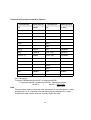
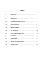
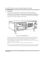

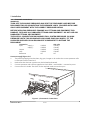
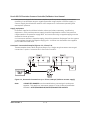
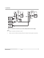
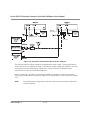
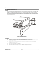


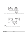
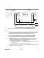
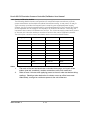
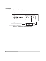
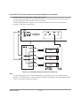
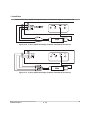

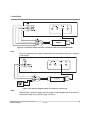


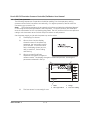
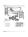
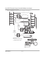
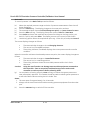
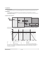
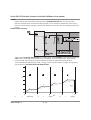
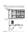
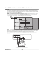
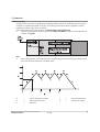

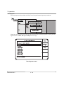
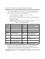


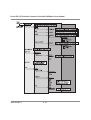
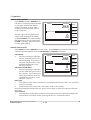
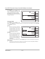
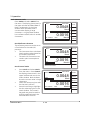

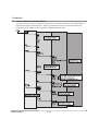

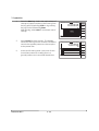


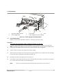
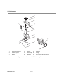
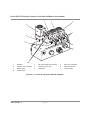
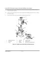


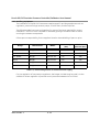


![RC400G Residual Chlorine Analyzer [Style: S3]](http://vs1.manualzilla.com/store/data/005893183_1-484cd185856d4428f9cc01b01a19e45f-150x150.png)