Download GlyCount User Manual.book
Transcript
Operator Manual
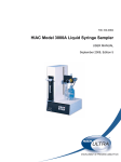
hiac GlyCount
Portable Glycol Analysis System
Operator Manual
hiac GlyCount
Portable Glycol Analysis System
GlyCount - Table of Contents
1 of 72
Table of Contents
1
Introduction
1.1
1.2
2
Display and Keypad Operation
2.1
2.2
3
RPS - 12 December 2007 - Edition 1
Displayed Information ............................................................................ 25
Interpretation of Results......................................................................... 26
Buffer Operation
8.1
8.2
8.3
9
Bottle Mode............................................................................................ 23
Online Mode........................................................................................... 23
Filter Mode ............................................................................................. 24
Test Results
7.1
7.2
8
Bottle Sampling...................................................................................... 19
Online Sampling..................................................................................... 20
Flushing the GlyCount ........................................................................... 21
Fluid Compatibility.................................................................................. 22
Taking a Sample
6.1
6.2
6.3
7
External Pressure Sources .................................................................... 15
Programming Operation Variables......................................................... 15
Sample Handling Procedures
5.1
5.2
5.3
5.4
6
Self-test Verification ............................................................................... 13
Setup and Programming
4.1
4.2
5
Using the Keypad................................................................................... 11
Understanding the Display..................................................................... 12
Functional Verification
3.1
4
General Equipment Description ............................................................... 7
Unpacking Instructions........................................................................... 10
Viewing the Contents ............................................................................. 27
Deleting and Printing.............................................................................. 27
Sample Data .......................................................................................... 27
Communications
9.1
9.2
Remote Serial Interface (RS-232 Port) .................................................. 29
Input/Output Interface (I/O Port) ............................................................ 30
Operator Manual
2 of 72
Table of Contents - GlyCount
10
Maintenance and Service
10.1
10.2
10.3
10.4
11
Changing the Filter................................................................................. 31
Charging the Battery .............................................................................. 32
Changing the Printer Paper ................................................................... 33
Removing Flow Sensor Blockages ........................................................ 33
Troubleshooting
11.1 Procedural Problems ............................................................................. 35
11.2 Fatal Error Messages............................................................................. 35
11.3 Non-Fatal Error Messages..................................................................... 42
Appendix A: Service Procedures ............................................... 43
A.1
A.2
A.3
Calibration.............................................................................................. 43
Return Procedures................................................................................. 43
Technical Support Information ............................................................... 44
Appendix B: Performance Specifications.................................. 45
Appendix C: Accessories............................................................ 47
Appendix D: Reference Documents ........................................... 49
D.1
Flow Diagram......................................................................................... 49
Appendix E: Cleanliness Codes ................................................. 51
E.1
E.2
Classification.......................................................................................... 51
Codes..................................................................................................... 52
Appendix F: Applicable Standards ............................................ 55
RPS - 12 December 2007 - Edition 1
Appendix G: Glossary.................................................................. 57
Operator Manual
GlyCount - Manual Overview
3 of 72
Manual Overview
About This Manual
The information in this manual has been carefully checked and is believed to be accurate.
However, Hach Ultra assumes no responsibility for any inaccuracies that may be contained in
this manual. In no event will Hach Ultra be liable for direct, indirect, special, incidental, or
consequential damages resulting from any defect or omission in this manual, even if advised of
the possibility of such damages. In the interest of continued product development, Hach Ultra
reserves the right to make improvements in this manual and the products it describes at any
time, without notice or obligation.
Published in the United States of America
Hach Ultra P/N: 701247, Edition 1, 12 December 2007
Copyright © 2007 by Hach Ultra Analytics, Inc.
All rights reserved. No part of the contents of this manual may be reproduced or transmitted in
any form or by any means without the written permission of Hach Ultra Analytics, Inc.
Safety Conventions
WARNING
A warning is used to indicate a condition which, if not met, could cause serious personal injury
and/or death. Do not move beyond a warning until all conditions have been met.
CAUTION:
A caution is used to indicate a condition which, if not met, could cause damage to the
equipment. Do not move beyond a caution until all conditions have been met.
Note:
A note is used to indicate important information or instructions that should be considered
before operating the equipment.
General Safety Considerations
RPS - 12 December 2007 - Edition 1
These safety guidelines should be read carefully and understood before operating the
HIAC GlyCount.
• All service procedures should be conducted by properly trained service personnel.
• Make sure the Portable Glycol Analysis System is properly installed and all hydraulic
connections are correctly installed before operation. Online operation may use highpressure. All safety guidelines should be observed when using high-pressure devices.
• Follow all procedures in “Return Procedures” on page 43 before shipping a unit to a
service center for repair or re-calibration.
WARNING
Only factory certified personnel should perform service of the GlyCount. Attempts by untrained
personnel to disassemble, alter, modify or adjust the electronics and/or hydraulics may result
in personal injury and damage to the GlyCount.
Operator Manual
4 of 72
Manual Overview - GlyCount
HIAC GlyCount Operator Manual Addendum: Cleaning Instructions Warning
WARNING
Do not spray the GlyCount with cleaning solutions to clean the unit. Apply all cleaning
solutions, including combustible solvents, with a clean cloth. Remove all combustible solvent
residues before connecting or removing the power supply; otherwise, injury or death to
personnel and/or damage to the GlyCount may occur.
Like all power supplies, the GlyCount power supply may produce and electrical spark when
connected or disconnected to the GlyCount. The unit is not hermetically sealed, and a spark
may ignite residual solvent. Spraying the GlyCount with any cleaning solutions will void the
warranty and may result in injury or damage.
The pick-up tube is used to make the hydraulic connection between the GlyCount and the
online adapter.
CAUTION:
Care must be taken not to bend the pick-up tube or scratch the lower end where the seal
connection is made. Damage may cause leakage or misalignment with the online adapter.
The CO2 bottle is a compressed gas cylinder under high pressure. Do not alter this cylinder in
any way. Do not over-pressurize the cylinder. Do not expose the pressurized cylinder to
temperatures in excess of 350 °F (177 °C). Valves must be installed or removed only by trained
personnel. Cylinders exposed to a fire or heated to temperatures in excess of 350 °F (177 °C)
should be condemned or hydrostatically tested prior to filling. Do not use caustic cleaners. Do
not remove or cover the label on the cylinder.
WARNING
Release of the gas under uncontrolled conditions will result in a freezing spray. Improper use,
filling, storage, or disposal of this cylinder may result in death, personal injury, and property
damage.
Keep cylinder out of reach of children. This cylinder must only be filled by properly trained
personnel in accordance with CGA Pamphlets P.1 and G-6.3 available from the Compressed
Gas Association, 1235 Jefferson Davis Highway, Arlington, Virginia, 22202. It is unlawful to
ship a filled CO2 bottle within the USA due to the high pressure of its contents.
Follow all described procedures in “Return Procedures” on page 43 before shipping a unit to a
service center for repair or re-calibration.
• Laser Safety – Class 1 Laser Product – Complies with 21 CFR Chapter 1, Subchapter J
Operator Manual
RPS - 12 December 2007 - Edition 1
CAUTION:
Use of controls, adjustments, or performance of procedures other than those specified herein
may result in hazardous radiation exposure.
GlyCount - Manual Overview
5 of 72
WARNING
The following DANGER label is clearly visible on the body of the laser sensor inside the unit.
Do not disassemble or attempt to service due to the possibility of eye damage.
The bottle adapter is a pressure vessel used for sample delivery through the GlyCount. It is
critical that it is installed in the locked position before sampling. The bottle adapter must be
aligned on the GlyCount and in the locked position.
WARNING
If the bottle adapter is not installed properly when pressurization begins, it can be forced off of
the GlyCount and personal injury and/or damage to the GlyCount may occur.
Although the GlyCount is designed for rugged use, it is still an instrument that should be cared
for and maintained as described in this manual. Following proper safety and handling
instructions will promote accident free operation and prolong product life.
Warranty
Hach Ultra warrants that this instrument will be free of defects in materials and workmanship
for a period of one (1) year from the shipping date. If any instrument covered under this
warranty proves defective during this period, Hach Ultra will, at its option, either repair the
defective product without charge for parts and labor, or provide an equivalent replacement in
exchange for the defective product.
RPS - 12 December 2007 - Edition 1
To obtain service under this warranty, the customer must notify the nearest Hach Ultra service
support center on or before the expiration of the warranty period and follow their instructions for
return of the defective instrument. The customer is responsible for all costs associated with
packaging and transporting the defective unit to the service support center, and must prepay
all shipping charges. Hach Ultra will pay for return shipping if the shipment is to a location within
the same country as the service support center.
This warranty shall not apply to any defect failure or damage caused by improper use or
maintenance or by inadequate maintenance or care. This warranty shall not apply to damage
resulting from attempts by personnel other than Hach Ultra representatives, or factoryauthorized and trained personnel, to install, repair or service the instrument; to damage
resulting from improper use or connection to incompatible equipment; or to instruments that
have been modified or integrated with other products when the effect of such modification or
integration materially increases the time or difficulty of servicing the instrument.
THIS WARRANTY IS GIVEN BY HACH ULTRA WITH RESPECT TO THIS INSTRUMENT IN
LIEU OF ANY OTHER WARRANTIES, EXPRESSED OR IMPLIED. HACH ULTRA
ANALYTICS AND ITS VENDORS DISCLAIM ANY IMPLIED WARRANTIES OF
MERCHANTABILITY OR FITNESS FOR A PARTICULAR NON-CONTRACTUAL PURPOSE.
HACH ULTRAS’ RESPONSIBILITY TO REPAIR OR REPLACE DEFECTIVE PRODUCTS IS
THE SOLE AND EXCLUSIVE REMEDY PROVIDED TO THE CUSTOMER FOR BREACH OF
Operator Manual
6 of 72
Manual Overview - GlyCount
THIS WARRANTY. HACH ULTRA AND ITS VENDORS WILL NOT BE LIABLE FOR ANY
INDIRECT, SPECIAL, INCIDENTAL, OR CONSEQUENTIAL DAMAGES EVEN IF HACH
ULTRA OR ITS VENDORS HAS BEEN GIVEN ADVANCED NOTICE OF THE POSSIBILITY
OF SUCH DAMAGES.
Acknowledgements
RPS - 12 December 2007 - Edition 1
• Aflas is a registered trademark of Asahi Glass Co., Ltd. Corporation.
• Microsoft, Windows, Windows 98, Windows 2000, and Windows XP are trademarks or
registered trademarks of Microsoft Corporation.
• Minimess is a registered trademark of Hydrotechnik GmbH Corporation of the Federal
Republic of Germany.
• Skydrol is a registered trademark of Solutia, Inc.
Operator Manual
GlyCount - Introduction
1
7 of 72
Introduction
The Portable Glycol Analysis System (GlyCount) is an intelligent, portable, and robust analysis
instrument for measuring, storing, and reporting glycol contamination important for reliable filter
system operation. The GlyCount provides the means to analyze pressurized fluids and
lubricants in online or bottle sampling modes without interrupting machine operations.
The GlyCount is compatible with glycol hydraulic fluids, including MIL-H-5606 and Skydrol®.
It is capable of online sampling at pressures up to 207 bar (3000 psi) and temperatures to
65 °C (149 °F). The GlyCount comes with refillable CO2 bottles for low running costs while in
the field and a shop-air port fitting for in-house operation.
Note:
Due to US shipping restrictions, the GlyCount is shipped with empty CO2 bottles.
Features of the GlyCount include:
•
•
•
•
•
•
•
•
•
Eight channel display
Bottle or online sampling
500 sample memory
High speed thermal printer
Flash programmable
Aluminum alloy sheet metal construction
Built-in bottle sampler pressure chamber
Compact power supply
Refillable CO2 bottle
1.1 General Equipment Description
RPS - 12 December 2007 - Edition 1
The GlyCount is shown in Figure 1-1, Figure 1-2, and Figure 1-3.
Operator Manual
8 of 72
Introduction - GlyCount
slot for printout of keypad displays
keypad display area
keypad
left side
right side
RPS - 12 December 2007 - Edition 1
Fig 1-1 : Front View
Operator Manual
GlyCount - Introduction
9 of 72
handle
shoulder strap D-ring
CO2 bottle
sample bottle adapter
Fig 1-2 : Right Side View
shoulder strap D-ring
clean-out port
pressure gauge
RPS - 12 December 2007 - Edition 1
power input port
RS-232 port
waste bottle
shop air port
Fig 1-3 : Left Side View
Operator Manual
10 of 72
Introduction - GlyCount
1.2 Unpacking Instructions
The GlyCount comes in a rugged plastic shipping container that includes casters and a
convenient extension handle that makes transportation much easier. There are three standard
handles and seven locking tabs around the perimeter of the lid. The container can be secured
with the two padlock holes located on the front of the lid.
Remove any cardboard packaging material and place the shipping container on a level
surface with the lid oriented on the top side.
2) Unlatch the seven locking tabs and lift the lid to an upright position.
3) Lift the GlyCount from the shipping container and place it on a flat surface in an upright
position.
4) Remove the protective layer of plastic.
The GlyCount is now ready to set up and operate.
RPS - 12 December 2007 - Edition 1
1)
Operator Manual
GlyCount - Display and Keypad Operation
2
11 of 72
Display and Keypad Operation
2.1 Using the Keypad
Figure 2-1 shows the features included on the keypad. There are four function keys that are
reused throughout the menu tree.
• The POWER key toggles the power ON and OFF.
• The START key initiates a sample test.
• The CANCEL key cancels a sample test or cancels a programming function and
maintains the previous selection.
• The LINE FEED key feeds the printer paper.
• The arrow keys are used to select operating variables and move the cursor left and right.
power key
battery charging
status light
display area
alphanumeric
keypad
START key
CANCEL key
LINE FEED key
arrow keys
function keys
Fig 2-1 : Keypad Features
RPS - 12 December 2007 - Edition 1
The display area provides the user with information on the counting process, error codes,
sample test results, and the status of the operating variables. The Battery Charging Status
lights indicate the current mode of operation for the charging system. See “Charging the
Battery” on page 32 for more information.
The alphanumeric keys allow the user to input letters and numbers into the program. To input
letters, simply press the key that contains the letter successively until the letter appears. Press
once for the number, twice for the first letter, three times for the second letter, etc. Press the
right arrow key to accept the current letter and move the cursor to the next character location.
In certain programming menus, symbols may be entered by pressing the function keys that
indicate the symbol to be used. Press F1 for a space, F2 for a forward slash, and F3 for a
period.
Operator Manual
12 of 72
Display and Keypad Operation - GlyCount
2.2 Understanding the Display
Along the bottom of the display are four bordered areas that correspond to four function keys,
shown in Figure 2-1. These bordered areas display the attributes of the function keys and will
change for different menus. To activate an attribute, press the function key that corresponds to
the desired attribute.
RPS - 12 December 2007 - Edition 1
The remainder of the display area shows information about the current menu, the results of a
sample test, error messages, and act as a user interface during operation, in combination with
the keypad.
Operator Manual
GlyCount - Functional Verification
3
13 of 72
Functional Verification
3.1 Self-test Verification
When the "POWER" key is pressed, the GlyCount startup screen appears as shown in
Figure 3-1.
Fig 3-1 : GlyCount Startup Screen
Next, the GlyCount initialization screen appears as shown in Figure 3-2:
INITIALIZING
SYSTEM
PLEASE WAIT...
Serial Number
000000000
208XXXX-XX
Fig 3-2 : GlyCount Initialization Screen
At this point, the GlyCount checks its internal systems for any problems. If a problem is found,
the GlyCount displays an error message. For an explanation of the possible reasons for these
errors, please see “Troubleshooting” on page 35. The firmware number can be verified at this
stage for questions concerning firmware.
RPS - 12 December 2007 - Edition 1
a ) System Status Menu
Under the main menu, there is a system status menu. It can be accessed by pressing the F3
(SYS) key. This menu displays various system parameters that the GlyCount measures. The
displayed parameters include:
• Power Supply
• Internal Temperature
• Printer Status
Operator Manual
14 of 72
Functional Verification - GlyCount
The “Power Supply” screen will indicate whether the GlyCount is connected to the external
power supply or is operating from the internal battery. During external power supply operation,
the battery icon will indicate that the internal battery is under charging control. During battery
operation, the battery icon will indicate the relative battery supply voltage capacity remaining.
The useful battery voltage range for the GlyCount is 13.8 to 11.5 volts. The amount of battery
life remaining below this range is minimal, so preparation for charging should be made before
continuing operation.
The “Internal Temperature” screen indicates the temperature inside the GlyCount enclosure.
It does not indicate the ambient temperature. This measurement determines if it is too hot or
cold to perform a sample test.
The “Printer Status” screen shows the different status conditions or errors of the internal printer.
A condition of “NORMAL” indicates the printer is functioning properly. An error message
displays if a problem exists. See “Troubleshooting” on page 35 for an explanation of these error
codes.
RPS - 12 December 2007 - Edition 1
These system parameters display convenient information and diagnostic troubleshooting.
Operator Manual
GlyCount - Setup and Programming
4
15 of 72
Setup and Programming
4.1 External Pressure Sources
A CO2 bottle or a “shop air” pressure source can be connected to the GlyCount to supply the
external pressure. The following sections describe the requirements for each option:
a ) CO2 Bottles
Due to varying shipping rules and regulations, the CO2 bottles contained in the shipping
container will not be filled with CO2. The bottles must be filled by a certified CO2 supplier before
use. Once filled, inspect the threads and O-ring for damage before connecting to the GlyCount.
A clean lubricant is recommended for ease of use and to prevent damage to the O-ring.
To use a CO2 bottle as an external pressure source:
1) Screw a bottle clockwise into the CO2 port of the GlyCount.
As the bottle is threaded into the CO2 port, the bottle valve will be opened and pressure will
be applied to the GlyCount. When this occurs, the bottle will become difficult to turn.
2)
Continue another ¼ turn until the bottle stops. If CO2 begins to vent around the bottle
threads when this pressurization occurs, remove the CO2 bottle and inspect the O-ring
for damage.
b ) Shop Air
A compressed air source can also be connected to GlyCount at the shop air port. It must be
clean, dry and between 90 to 110 psi (6.2 to 7.6 bar). If the shop air nipple included does not
interchange with the system, install a new one. A 1/8-inch male NPT connection is required. Be
sure to clean the port threads thoroughly before installing the new fitting to prevent debris from
entering the pneumatic system.
Before attempting to connect any pressure source to the GlyCount, be sure to read the
“General Safety Considerations” on page 3.
4.2 Programming Operation Variables
RPS - 12 December 2007 - Edition 1
The operation variables are located under the Setup menu. They consist of the following:
Operator Manual
16 of 72
Setup and Programming - GlyCount
a ) Setup Menu
1)
SAMPLE LABEL: Selecting this variable will display a second menu, “Sample Text”
menu. Under this menu the operator can program the following items:
• SAMPLE LABEL “SAMPLE NAME”: User-input name for samples. The
sample labels can be 10 characters long. For each sample label there is an
auto-counter extension that increments up to 500. This extension is reset to
one every time a new sample label is programmed, reentered, or exceeds a
count of 500.
• REMARKS: User-input remarks for any additional sample labeling, as
desired. These optional remarks become part of the record of any completed
samples. Records retrieved from the sample buffer can have their remarks
reviewed and reedited as necessary. The sample remarks can be 10
characters long on any of three lines. Any existing remarks display on printed
sample reports.
2)
MODE: (BOTTLE or ONLINE FILTER) Sampling method
3)
4)
5)
6)
7)
Operator Manual
STD: (ISO(C), ISO, NAS(C), NAS, NAV(C), NAV, SAE(C), SAE, MIL, P/10ml or P/1ml)
Determines the Standard format to display the sample results.
VOL: (5, 10, 20, 50, or 100 ml) Volume of fluid that will be run three times during a
sample (Volume/RUN). BOTTLE mode sampling is limited to 5, 10, or 20 ml per RUN
only.
FLOW: The flow rate is fixed at 50 ml/min.
PRINT: (ENBL, DSBL or SETUP) Enables or disables the printer from automatically
printing at the end of a sample. SETUP will print the current GlyCount setup.
CONTRAST: (Left/right arrow keys) Controls the display contrast.
RPS - 12 December 2007 - Edition 1
• If BOTTLE mode is selected or reentered, a second screen displays to allow
programming of the following variable:
• PURGE VOL: (15-30 ml) Volume of fluid that will flow through the unit to
purge any contamination before sampling.
• If ONLINE mode is selected or reentered, a second screen displays to allow
programming of the following variables:
• NUM SAMPLES: (1-500) Numbers of samples that will run during the
sampling period.
• HOLD TIME: (Hours/Minutes) Time delay from the end of a sample to the
start of the next sample. If set for 00:00, a minimum 5-second hold time will
be set.
• PURGE VOL: (15-999 ml) Volume of fluid that will flow through the hydraulic
hose and unit to purge any contamination before sampling. The longer the
hydraulic hose, the greater the purge volume must be.
GlyCount - Setup and Programming
17 of 72
b ) Screen: PG 2
1)
2)
3)
4)
5)
6)
7)
LANG: (English, French, German, Span, and Ital) Determines the language that will be
used in the operation and control of the GlyCount.
TEMP: (°C or °F) Determines the units to display temperature.
PRESS: (BAR or PSI) Determines the units to display pressure.
DISPL: (NORM or REV) Display viewed as light background (Normal) or dark
background (Reversed).
BKLT: (ON, OFF, or AUTO) Controls the LCD display’s back light. If AUTO is selected,
the back light will turn off after five minutes of inactivity.
BEEP: (KEY or DSBL) Controls audio feedback of the beeper when a key is pressed.
BSAVE (battery save feature): This item is either "ENBL" (Enabled), or "DSBL"
(Disabled). If enabled, the GlyCount will automatically shut off after 15 minutes of no
activity (Idle state).
c ) Screen: SIZ:
Programmable size menu. When MODE is set to P/1ml or P/10ml, PG2 menu becomes
available for programming of any of the eight size channels. The minimum and maximum size
programming is limited to a range of 4.0 to 68.0 μm, respectively. Size programming must also
be in an ascending order from the smallest size on channel 1 to the largest size on channel 8.
Note:
The DEFAULT key (F2) may be used to reset all sizes to factory default settings.
d ) Screen: I/O:
1)
RPS - 12 December 2007 - Edition 1
2)
UNIT ID: (01 - 99) This programmable variable is used to set a unique device address
used in serial communication of the GlyCount MODBUS protocol.
CNTRL: (LOCAL, REMOTE, or DOWNLOAD) Set to LOCAL when the GlyCount is
manually operated. Set to REMOTE when a computer program operates and controls
sampling of the GlyCount. Set to DOWNLOAD when a computer program is retrieving
the records from the sample buffer only. The setting of this variable can also be
changed automatically through the serial MODBUS protocol.
Operator Manual
18 of 72
Setup and Programming - GlyCount
e ) Screen: CLK:
1) TIME: (Hours/Minutes/Seconds) Current time in 24-hour format.
2) DATE: (Month/Day/Year) Current date.
To program any operation variable, press the numeric number on the keypad that
corresponds to the number on the left side of the variable to program. Press the F1 (PRG)
function key and use the left/right arrow keys to select the proper setting or use the keypad
1
2
to input numbers, letters or symbols . Press the F4 (↵) function key to accept the new
setting or press “CANCEL” to return to the Setup menu and maintain the previous selection.
1. To input letters, simply press the numeric key that contains the letter to use in succession. Press once for the number, twice for the
first letter, three times for the second letter, etc. The interval between the key presses determines if the current character is selected
or if the next character will be selected.
2. To input symbols, simply press the function key that indicates the symbol to use. Press F1 for a space, F2 for a forward slash, and F3
for a period.
Operator Manual
RPS - 12 December 2007 - Edition 1
To view test results in a different Standard or Temperature, simply program the desired
variables and view or print the test results from the buffer (see “Test Results” on page 25).
GlyCount - Sample Handling Procedures
5
19 of 72
Sample Handling Procedures
Sample handling procedures are very important for obtaining a representative sample of the
contamination level of the system under test. The sample should be taken from a source with
moving fluid.
Note:
If the sample is taken from a slow-moving stream (a “dead-leg”), a non-representative sample
may result. It is recommended that a system be running for at least 30 minutes before a
sample is taken.
Flushing of the GlyCount is also an essential procedure to obtain an accurate and
representative sample. Upon finishing the previous series of tests, the sample still resides in
the GlyCount. This fluid must be flushed out with a fluid that will not contaminate the next
sample. Reducing contamination results in more statistically significant results.
For best results, flush the GlyCount with the same fluid type as intended for the next sample.
Mixing or using other fluid types may cause sampling errors due to fluid incompatibility.
With online operation, the GlyCount will be flushed with the fluid to be tested. For proper
flushing, the flush volume must be approximately twice that of the internal volume of the
hydraulic hose that connects the GlyCount to the system to be tested.
Maximum flushing before sampling will ensure an accurate sample measurement. However,
excessive flushing will result in premature clogging of the filter. See “Flushing the GlyCount” on
page 21 for flushing instructions.
5.1 Bottle Sampling
Common sources of contamination inadvertently added to fluid samples come from the bottles,
pick-up tube, and airborne particles. Only clean sample bottles should be used and they should
be kept covered at all times.
As with any light blockage optical technology, sample inaccuracies will result from excess air
and entrained gas. Both will be counted as particles. Ideally, air bubbles should be removed by
applying a vacuum to the sample in a vacuum chamber or by placing the sample in an
ultrasonic bath for several seconds.
RPS - 12 December 2007 - Edition 1
Particles settle to the bottom of a sample bottle within minutes, so a sample should be shaken
to re-suspend the particles and degas to remove bubbles.
Highly contaminated samples will saturate the sensor, making particle count data invalid.
The GlyCount’s limit is 20,000 particles per ml at 5% coincidence loss (per ISO11171) and
30,000 particles per ml at 10% coincidence loss of fluid for a specific size. A general rule-ofthumb to follow is that if contamination can be seen suspended in a fluid sample, the sample
may contain concentrations beyond the saturation limits of the GlyCount. The average person
can only see particles greater than 40 μm in size.
Operator Manual
20 of 72
Sample Handling Procedures - GlyCount
Sample fluids can be drawn from reservoirs with the use of the “vampire pump” that is included
in the shipping container.
1)
2)
3)
4)
5)
Cut a length of “clean” tube that can extend from the fluid in the reservoir to a point
accessible from outside the reservoir.
Thread a clean sample bottle into the vampire pump. Install one end of the tube into the
vampire pump so that it extends into the sample bottle and tighten the knurled knob.
Install the other end of the tube into the reservoir, being careful not to contaminate the
end of the tube.
Actuate the vampire pump’s piston until the sample bottle is filled to the desired level.
Disconnect the sample bottle from the vampire pump and install the cap until the
sample is ready to test.
5.2 Online Sampling
If handled properly, this is the most reliable method of obtaining a representative sample from
a system. The hydraulic hose that connects the GlyCount to the system being tested must be
purged to remove the previous fluid that was tested. Program the GlyCount for a purge volume
approximately twice that of the internal volume of the hydraulic hose to be used.
The importance of the location of the systems test port for accurate sampling should not be
underestimated. An application specialist should be consulted before installation of this port.
Additional fluid control devices should not be installed on the hydraulic sample hose or the
system’s test port. These devices can generate bubbles and create particle traps that may
cause sample inaccuracies.
Suitable sampling points for online measurements with the GlyCount:
RPS - 12 December 2007 - Edition 1
• Upstream of the high pressure filter (condition after pump)
• Upstream of the return filter (condition after system)
• Upstream of the bypass filter (tank condition)
Operator Manual
GlyCount - Sample Handling Procedures
21 of 72
5.3 Flushing the GlyCount
The GlyCount can be flushed in both bottle and online modes.
a ) Flushing in Bottle Mode
1)
2)
3)
4)
5)
6)
Verify that a CO2 bottle or shop air pressure source has been connected to the
GlyCount and that there is 90 to 110 psi (6.2 to 7.6 bar) indicated on the pressure
gauge.
Disconnect the bottle adapter from the GlyCount by turning the adapter clockwise.
Fill a sample bottle with the fluid to be flushed. Place the sample bottle into the Bottle
Adapter and reconnect it to the GlyCount by sliding the pick-up tube into the sample
bottle and turning the adapter clockwise until locked.
From the main menu, press the F4 key to go into the flush menu and press “START.”
Press F1 (SOL ON). The bottle adapter pressurizes and fluid begins to exit the drain
port. The amount of fluid being flushed is indicated on the display.
When the desired amount of fluid has been flushed, press “CANCEL” to stop flushing
and return to the main menu.
CAUTION:
If the flushed volume exceeds the amount of fluid in the bottle adapter, pneumatic pressure will
be flushed through the GlyCount and out of the drain port. This can create air pockets in the
filter system and lead to sampling errors.
b ) Flushing in Online Mode
1)
2)
3)
4)
5)
Connect the online adapter to the GlyCount by sliding the pick-up tube into the hole in
the center of the adapter and turning counter clockwise until locked.
Connect a hydraulic hose with a Minimess® test hose thread to the online adapter.
Connect the other end of the hydraulic hose to the system to be tested.
From the main menu, press the F4 key to go into the flush menu and press “START.”
Fluid will begin to exit the drain port and the amount of fluid being flushed is indicated
on the display.
When the desired amount of fluid has been flushed, press “CANCEL” to stop flushing
and return to the main menu.
CAUTION:
RPS - 12 December 2007 - Edition 1
Turning the power off while flushing causes the internal flow controller to remain open and
allows fluid to continue flowing. Always cancel the flushing process and allow five seconds to
pass before turning the GlyCount off.
Operator Manual
22 of 72
Sample Handling Procedures - GlyCount
5.4 Fluid Compatibility
The GlyCount is compatible with most glycol based fluids within the specified viscosity and
temperature ranges. If the compatibility of a desired fluid is in question, its compatibility should
be checked against the wetted material list included in the “Performance Specifications” on
page 45. If the compatibility cannot be determined, submit a request to a local Hach Ultra
representative for a recommendation on the fluid’s use within the GlyCount. Refer to “Technical
Support Information” on page 44 for contact information.
Note:
RPS - 12 December 2007 - Edition 1
GlyCount internal components are not compatible with water. Water may cause instrument
malfunction and damage. Glycount is only compatible with fluids containing lubricating and
corrosion protection properties such as Ethylene Glycol.
Operator Manual
GlyCount - Taking a Sample
6
23 of 72
Taking a Sample
6.1 Bottle Mode
In this mode, a sample fluid is placed into the Bottle Adapter and connected to the GlyCount.
An external pressure source is used to force the sample fluid through the GlyCount.
1)
Set the sampling mode to “BOTTLE” and verify the other operation variables are
programmed as needed. See “Programming Operation Variables” on page 17 for more
information.
2) Verify that a CO2 Bottle or shop air pressure source has been connected to the
GlyCount and that there is 90 to 110 psi (6.2 to 7.6 bar) shown on the pressure gauge.
Due to regulation variances, the pressure shown on the pressure gauge may creep up
to 120 psi (8.3 bar) during no flow conditions. The pressure should drop when a sample
is started.
3) Disconnect the bottle adapter from the GlyCount by turning counter-clockwise.
4) Fill a sample bottle with the fluid to be tested.
5) Place the sample bottle into the bottle adapter and re-connect it to the GlyCount by
sliding the pick-up tube into the sample bottle and turning clockwise until locked.
6) Double-check to make sure the waste bottle can accommodate the fluid.
7) Press “START.”
The sampling process begins.
• The Bottle Adapter pressurizes and fluid exits from the drain port.
• The GlyCount has a fixed flow rate (50 ml/min). There are three consecutive sample
runs at 5, 10, or 20 ml, depending on what was programmed.
When this process is completed, the test results are stored in the buffer, presented on the
display and/or printed if the printer is enabled.
6.2 Online Mode
In this mode, a sample can be fed directly from a filter system. The reduced probability of
contamination makes this the most accurate method of sampling. The CO2 or shop air external
pressure sources are not used in this mode because the hydraulic pressure forces the fluid
through the GlyCount. However, they can remain connected during the sampling process if
desired.
RPS - 12 December 2007 - Edition 1
1)
2)
3)
Set the sampling mode to “ONLINE” and program the desired number of runs, hold
time, and purge volume. The purge volume should be approximately twice the internal
volume of the hydraulic tube that connects the GlyCount to the system. Verify that the
other operation variables are programmed as needed. See “Programming Operation
Variables” on page 17 for more information.
Connect the online adapter to the GlyCount by sliding the pick-up tube into the hole in
the center of the adapter and turning clockwise until the adapter is locked.
Connect a hydraulic hose with a Minimess test hose thread to the online adapter.
Connect the other end of the hydraulic hose to the system to be tested.
Operator Manual
24 of 72
Taking a Sample - GlyCount
4)
Press “START.” The sampling process begins and fluid will begin to exit from the
drain port.
The GlyCount has a fixed flow rate (50 ml/min). There are three consecutive sample runs at
5, 10, 20, 50, or 100 ml, depending on what was programmed.
When this process is completed, the test results will be stored in the buffer, presented on the
display and/or printed if the printer is enabled.
CAUTION:
Turning the power off on the GlyCount while sampling will cause the internal flow controller to
remain open and allow fluid to continue flowing. Always allow the sampling process to finish or
press cancel and allow five seconds to pass before turning the GlyCount off.
6.3 Filter Mode
The Filter Mode is designed to allow the user to monitor the fluid cleanliness level while filtering
fluid. The user has to program sampling parameters, including sampler intervals, and target
cleanliness levels. The GlyCount will take samples at programmed intervals while the system
fluid is being filtered.
When the system fluid meets the programmed cleanliness level, the GlyCount will run an
additional sample to confirm the fluid cleanliness level is stable. The GlyCount will then beep,
stop sampling, and print the last two sample results if the printer is enabled. If the filter pump
ON/OFF control solenoid is connected to the GlyCount via the optional I/O connection, then the
pump will be turned ON when the filter start function is selected. The filter pump will
automatically be turned OFF when the cleanliness level is achieved.
• Set the sampling mode to “FILTER,” program the desired hold time, purge volume and
cleanliness level required. Verify the other operation variables are programmed as
needed. See “Programming Operation Variables” on page 15 for more information.
• Connect the Online Adapter to the GlyCount by sliding the pick-up tube into the hole in
the center of the adapter and turning counterclockwise until locked.
• Connect a hydraulic hose with a M16 X 2 test hose thread to the online adapter.
Connect the other end of the hydraulic hose to the fluid source.
• OPTIONAL—Connect the filter pump solenoid control to the GlyCount I/O connector.
(See “Input/Output Interface (I/O Port)” on page 30 for I/O port pin configurations.)
• Press the “START” button on the keypad after the filtering process has begun to ensure
adequate press to deliver fluid to GlyCount unit. The GlyCount will run samples at the
program interval. When the target cleanliness is detected, GlyCount will terminate the
sampling process. Up to 500 test results will be stored in the buffer, presented on the
display and/or printed if the printer is enabled.
Operator Manual
RPS - 12 December 2007 - Edition 1
The GlyCount fluid pressure requirement varies with the fluid viscosity. Minimum pressure
must be maintained to regulate fluid flow through the GlyCount unit. The GlyCount selfregulates based on fluid pressure and viscosity variation during sampling and filtering.
GlyCount - Test Results
7
25 of 72
Test Results
7.1 Displayed Information
Figure 7-1 shows a typical test report. It indicates the name of the sample, serial number of the
unit that took the sample, date and time the sample was taken, volume per sample run, flow
rate, measured fluid temperature, concentration units, measured cleanliness in the desired
format, and the count data per micron size. The count data show the number of counts per
individual run and the average of the three runs.
GlyCount
GLYCOL SAMPLE REPORT
Sample: SAMPLENAME.1
Serial #: 000000000
APRIL 15, 2004
Time: 12:00:00
Sample Mode: ONLINE
Volume: 5 ml/RUN
Flowrate: 50 ml/min
Fluid Temp: 73.2 F
Reported Concentration:
Parts/1 ml
ISO Code: 18/116/8 (4µm/6µm/14µm) (µm(c))
SIZES
RUN1
RUN2
RUN3
AVG
4.0µm
1352.80
1324.00
1385/40
1353.40
4.6µm
405.00
406.00
427.60
412.87
6.0µm
330.40
323.00
333.20
328.87
9.8µm
7.00
11.40
13.00
10.47
14.0µm
2.20
1.60
2.20
2.00
21.2µm
0.60
0.00
0.00
0.20
38.0µm
0.00
0.00
0.00
0.00
68.0µm
0.00
0.00
0.00
0.00
***************************************
RPS - 12 December 2007 - Edition 1
Fig 7-1 : Sample Test Report
For ISO Standard reporting, the run volume determines the lowest level of the contamination
code. For a run volume of 5 ml the lowest reported ISO code level is 03/03/03. For a run volume
of 10 ml the lowest reported ISO code level is 02/02/02. For a run volume of 20 ml the lowest
reported ISO code level is 01/01/01. For additional information on this subject, see ISO 4406
“Hydraulic fluid power – Fluids – Code,” for defining the level of contamination by solid
particles.”
The temperature displayed is the temperature at the end of the hydraulic circuit inside the flow
controller. It is not a measurement of the incoming fluid temperature. The hydraulic circuit has
thermal masses that influence the temperature of the fluid. If the GlyCount is colder then the
Operator Manual
26 of 72
Test Results - GlyCount
fluid, there will be a temperature drop of the fluid while sampling. If the GlyCount is hotter, there
will be a temperature increase of the fluid while sampling.
7.2 Interpretation of Results
RPS - 12 December 2007 - Edition 1
The reported results should be compared to the corresponding target ranges for the system
being tested. Fluid treatment or replacement can then be determined.
Operator Manual
GlyCount - Buffer Operation
8
27 of 72
Buffer Operation
8.1 Viewing the Contents
The contents of the buffer can be accessed by several means. Under the buffer menu,
selecting “LAST SAMPLE” will display the results of the last sample that was performed.
Selecting “LIST BUFFER” will display the eight most recent sample names for further review.
Selecting “SEARCH BUFFER” will allow searching for a particular sample name by entering
the entire or partial name of the sample to be found.
Once a sample selection has been made the next or previous samples can be selected by
pressing the corresponding function keys.
The buffer contents will be displayed in the configuration that the GlyCount is currently
programmed for. To display the results in a different configuration, change the operation
variables to the desired configuration and view the buffer contents again.
8.2 Deleting and Printing
Under the buffer menu, pressing the F2 (DEL BUF) key will delete the entire buffer contents.
The GlyCount will display a confirmation message and to prompt the user to accept or deny the
operation.
Press the F3 (PRT BUF) key to print the entire buffer contents. The GlyCount will display a
confirmation message and prompt the user to accept or deny the operation.
To delete or print an individual sample test result, simply press the F1 (DEL SMP) or F2 (PRT
SMP) key while in the average count (AVG CNT) menu. The average count menu can be
accessed while viewing a sample selection.
8.3 Sample Data
RPS - 12 December 2007 - Edition 1
The sample data are viewed under two pages. When a sample selection has been made, the
GlyCount displays the sample statistics for that particular sample. The remainder of the sample
data can be viewed by pressing the average count (AVG CNT) function key.
Operator Manual
Buffer Operation - GlyCount
RPS - 12 December 2007 - Edition 1
28 of 72
Operator Manual
GlyCount - Communications
9
29 of 72
Communications
9.1 Remote Serial Interface (RS-232 Port)
The GlyCount is equipped with an RS-232 communications port. This port is used to
communicate with a computer for data acquisition, analysis, and remote operation. This section
gives the specifications and wire pin-outs for the RS-232 Port.
•
•
•
•
BAUD RATE: 9600 baud
Data Bits: 8 bits
Parity: None
Stop Bits: 2 bits
a ) DB-9 Serial Connection
If the computer or terminal has a 9-pin serial port with a male connector, use a standard serial
cable with one end male and the other female. The GlyCount is already configured as Data
Communication Equipment (DCE), so the use of a null-modem cable is not required. The cable
pin diagram is shown in Figure 9-1.
GlyCount
Cable
PC
DCD
1
1
DCD
TX
2
2
RX
RX
3
3
TX
DTR
4
4
DTR
SG
5
5
SG
DSR
6
6
DSR
CTS
7
7
RTS
RTS
8
8
CTS
RI
9
9
RI
DB9
DB9
DB9
DB9
FEMALE
MALE
FEMALE
MALE
RPS - 12 December 2007 - Edition 1
Fig 9-1 : RS-232 Cable Pin Diagram
Operator Manual
30 of 72
Communications - GlyCount
9.2 Input/Output Interface (I/O Port)
I/O Port Connection: Used for turning filter pump low voltage solenoid or relay.
Table 9-1 : I/O Connector Pin Function
Pin #
Function
Specification
1
Unused
2
Unused
3
Unused
4
Unused
5
Unused
6
Unused
7
Digital switch source voltage
+5VDC @ 25mA max
8
Digital switch driver
Open drain NFET
9
Unused
10
Unused
RPS - 12 December 2007 - Edition 1
Fig 9-2 : I/O Connector Pin Diagram
Operator Manual
GlyCount - Maintenance and Service
31 of 72
10 Maintenance and Service
This section describes how to clean and maintain the GlyCount.
10.1 Changing the Filter
1)
Locate the filter housing above the waste container, as shown in Figure 10-1.
filter housing nut
Fig 10-1 : Filter Housing Nut Location
2)
Using a one-inch socket wrench, loosen the filter housing nut in a counter-clockwise
direction.
3) Carefully remove the nut and the filter assembly, containing:
• Ten (10) micron filter element
• Spring
• Stainless washer
Note:
Some glycol may come out with the filter assembly.
4)
RPS - 12 December 2007 - Edition 1
5)
Check the contents of the new filter kit, part number 540-400-0025, to make sure the kit
includes the filter element, a spring, and a stainless washer.
Install the new parts in the installation sequence shown in Figure 10-2. Install filter with
the open end up.
filter
spring nut
Fig 10-2 : Filter Installation Sequence
Operator Manual
32 of 72
Maintenance and Service - GlyCount
6)
7)
Discard the old filter element, spring, and stainless washer.
Retighten the filter housing nut firmly but do not overtighten as the O-ring may be
damaged.
Note:
Do not replace o-ring with non Aflas O-ring.
10.2 Charging the Battery
The GlyCount can be powered by two sources:
• internal rechargeable battery or
• external power supply.
In addition to supplying power to the GlyCount for operation, the external power supply has an
additional purpose of charging the internal battery. The GlyCount can be operated while the
internal battery is being charged.
1)
To charge the internal battery, retrieve the external power supply and power cord from
the shipping container.
2) Plug the power cord into the external power supply and the other end of the power cord
into a 110V outlet.
3) Plug the external power supply jack into the GlyCount at the power port location.
Listen for a click and verify that the “Battery Charging Status” light, located on the keypad,
is illuminated. This light will indicate one of three charging status modes, shown in
Table 10-1.
Table 10-1 : Charging Status Indicators
Indicator
Charging Status
Steady green
Charging
Flashing green
Maintenance mode
Steady red
Battery charging failure
RPS - 12 December 2007 - Edition 1
While operating on a fully charged internal battery, the GlyCount can perform a minimum of 100
samples before needing to be recharged.
Operator Manual
GlyCount - Maintenance and Service
33 of 72
10.3 Changing the Printer Paper
1)
2)
3)
4)
5)
6)
Open the printer door.
Open the new roll of printer paper and orient it so the paper feeds from the bottom of
the roll toward the GlyCount.
While the GlyCount is ON, insert the paper into the printer and press the “LINE FEED”
key. The paper will feed through the printer.
Roll up the slack in the paper roll and push it into the paper holder.
Lift the free end of paper and close the printer door.
Tear off the excess paper.
Note:
In case of paper misalignment, lifting the lever on the left side of the printer will raise the printer
carriage. The paper can then be pulled straight and aligned. Lower the carriage before
operating printer.
10.4 Removing Flow Sensor Blockages
Follow the steps below to remove blockages from the flow cell. Use all precautionary steps to
prevent damage to the instrument and personnel injury.
1)
2)
3)
4)
5)
6)
7)
8)
Disconnect the power supply.
Disconnect the air source.
Remove the sample cup and adapter.
Place glycol absorbent cloth under the unit to capture any glycol draining from the
clean out port.
Retrieve the Allen wrench and cleaning brush from the shipping container.
Insert the wrench and turn counterclockwise to remove the clean-out port cap.
Slide the brush into the clean-out port until resistance is encountered.
Gently push the brush into the sensor flow cell with a twisting motion.
CAUTION:
Excessive pressure will result in brush and possible cell damage. If the brush will not go into
the cell, pull the brush out and inspect the cleaning tip for damage.
RPS - 12 December 2007 - Edition 1
9)
10)
11)
12)
Remove the cleaning brush and snug the clean-out port cap.
Reconnect the air source to the unit.
Run clean sample fluid through the instrument. Cover the wrench with glycol absorbent
cloth and slightly loosen the clean-out cap while the sample run is in progress to purge
any trapped air in the clean-out line. Fluid and air will squirt out of the clean-out port
when the cap is loosen. Continue the process until there is no remaining air exiting from
the port.
Tighten the clean-out port cap snugly. To avoid damaging the threads, do not over
tighten the cap.
Operator Manual
Maintenance and Service - GlyCount
RPS - 12 December 2007 - Edition 1
34 of 72
Operator Manual
GlyCount - Troubleshooting
35 of 72
11 Troubleshooting
The following list describes problems and error codes with recommended actions. If the
described actions do not solve the problem, contact the customer service center.
For program malfunctions, the GlyCount can be defaulted by pressing and holding the F4 key
while power is cycled.
Note:
This will erase the entire buffer contents and reset all of the operation variables to their factory
settings. The message “GlyCount DEFAULTING” and the Firmware part number will be
displayed as the GlyCount reinitializes its systems.
11.1 Procedural Problems
Sample runs out before test is complete:
• Sample bottle not properly filled.
• Programmed sample or purge volumes too large for the amount of sample.
• Trapped air volume in internal hydraulic tubing. Purge internal hydraulic tubing including
clean-out port.
• Internal hydraulic leak. Contact the customer service center for repair.
The GlyCount will not turn ON when “POWER” key is pressed:
• Battery voltage too low. Connect external power supply to GlyCount for operation and
charging.
11.2 Fatal Error Messages
a ) Flow Controller Failure
"
FLOW
"
"
CONTROLLER
"
"
FAILURE.
"
“
"
"
PLEASE SEE
"
"
OPERATING
"
“
MANUAL
"
RPS - 12 December 2007 - Edition 1
Fig 11-1 : Flow Controller Failure Error Message
Shown in Figure 11-1, the GlyCount is unable to detect the HOME switch on the flow controller
during system initialization or at the end of a sample test.
• Cycle the power to allow the GlyCount to re-initialize its systems.
• Flow controller wire harness disconnection.
• Flow controller malfunction. Contact the customer service center for repair.
Operator Manual
36 of 72
Troubleshooting - GlyCount
b ) Threshold Communication Failure
"
THRESHOLD
"
"
COMMUNICATION
"
"
FAILURE.
"
“
“
"
PLEASE SEE
"
"
OPERATING
"
“
MANUAL.
“
Fig 11-2 : Threshold Communication Failure Error Message
Shown in Figure 11-2, the GlyCount is unable to communicate with the Threshold Board.
Sampling will terminate and will not be allowed.
• Threshold Board wiring harness disconnection.
c ) Printer Initialization Failure
“
PRINTER
“
"
INITIALIZATION
"
"
FAILURE.
"
"
"
"
PLEASE SEE
"
"
OPERATING
"
"
MANUAL.
"
Fig 11-3 : Printer Initialization Failure Error Message
Shown in Figure 11-3, the GlyCount is unable to detect printer logic during system initialization.
RPS - 12 December 2007 - Edition 1
• Printer Board wiring harness disconnection.
Operator Manual
GlyCount - Troubleshooting
37 of 72
d ) Flow Regulation Failure
“
FLOW
“
"
REGULATION
"
"
FAILURE.
"
"
"
"
PLEASE SEE
"
"
OPERATING
"
"
MANUAL.
"
Fig 11-4 : Flow Regulation Failure Error Message
Figure 11-4 shows the message displayed when the GlyCount is unable to regulate flow rate
within operational parameters. The sample test in progress will terminate.
•
•
•
•
External pressure was depleted during sample test.
The GlyCount was not purged before a change in viscosity of the sample fluid.
Insufficient sample fluid.
Attempt to flush the system. See “Flushing the GlyCount” on page 21.
e ) Low Flow Rate
“
LOW
“
"
FLOW RATE
"
"
ERROR.
"
"
"
"
POSSIBLE
"
"
HIGH
"
Fig 11-5 : Low Flow Rate Error Message
Figure 11-5 shows the message displayed when the GlyCount is unable to regulate flow rate
above the operational lower limit. The sample test in progress will terminate.
RPS - 12 December 2007 - Edition 1
• External pressure was depleted during sample test.
• GlyCount not purged before a change in viscosity of the sample fluid.
• Pick-up tube cap not removed.
Operator Manual
38 of 72
Troubleshooting - GlyCount
f ) Insufficient Hydraulic Pressure
"
INSUFFICIENT
“
"
HYDRAULIC
"
"
PRESSURE
"
"
FOR
"
"
SAMPLING.
"
Fig 11-6 : Insufficient Hydraulic Pressure Error Message
Figure 11-6 shows the message displayed in online mode after one minute of waiting for
hydraulic pressure to increase above operational lower limit. Sampling will terminate.
• Hydraulic pressure source insufficient.
g ) High Pressure Detected
“
HIGH
“
"
PRESSURE
"
"
DETECTED.
"
"
"
"
POSSIBLE
"
"
REGULATOR
"
"
FAILURE.
"
Fig 11-7 : High Pressure Error Message
Figure 11-7 shows the message displayed when internal hydraulic pressure increases above
operational limit. Sampling will terminate.
RPS - 12 December 2007 - Edition 1
• Internal hydraulic regulator failure or adjustment setting out of tolerance. Contact the
customer service center for repair.
Operator Manual
GlyCount - Troubleshooting
39 of 72
h ) Low Pressure
“
LOW
“
"
PRESSURE
"
"
ERROR.
"
"
"
"
PLEASE SEE
"
"
OPERATING
"
"
MANUAL.
"
Fig 11-8 : Low Pressure Error Message
Figure 11-8 shows the message displayed in bottle mode after one minute of waiting for
hydraulic pressure to increase above operational lower limit. Sampling will terminate.
• External pressure source insufficient.
• Pick-up tube cap not removed.
i ) Insufficient Pressure
“
PRESSURE
“
"
DROPPED TO AN
"
"
INSUFFICIENT
"
"
LEVEL.
"
Fig 11-9 : Insufficient Pressure Error Message
Figure 11-9 shows the message displayed when internal hydraulic pressure drops below
operational limit. Sampling will terminate.
• External pressure was depleted during sample test.
• Internal hydraulic regulator failure or adjustment setting out of tolerance. Contact the
customer service center for repair.
RPS - 12 December 2007 - Edition 1
j ) High Internal Temperature
“
HIGH
“
"
INTERNAL
"
"
TEMPERATURE.
"
"
"
"
SAMPLING
"
"
NOT
"
"
ALLOWED.
"
Fig 11-10 : High Internal Temperature Error Message
Figure 11-10 shows the message displayed when the sample fluid temperature is above
operational limits. Sampling will not be allowed.
Operator Manual
40 of 72
Troubleshooting - GlyCount
k ) High Fluid Temperature
“
HIGH
“
"
FLUID
"
"
TEMPERATURE.
"
"
"
"
SAMPLING
"
"
ABORTED.
"
Fig 11-11 : High Fluid Temperature Error Message
Figure 11-11 shows the message displayed when the sample fluid temperature increases
above operational limits during a sample test. Sampling will terminate.
l ) Printer Error
“
PRINTER
“
"
ERROR BELOW
"
"
ERROR
"
Fig 11-12 : Insufficient Pressure Error Message
Figure 11-12 shows the message displayed when an attempt to print has been executed and a
printer error condition exists.
These error messages may appear on the printer:
"PAPEROUT" No printer paper installed.
"HEAD_V” Printer head voltage error. Contact the customer service center for repair.
"HEAD_UP" Printer head lever is in the up position. Lower lever.
"HEAD_T" Printer head temperature error. Ambient temperature too high.
"FAILURE" Printer head failure. Contact the customer service center for repair.
RPS - 12 December 2007 - Edition 1
•
•
•
•
•
Operator Manual
GlyCount - Troubleshooting
41 of 72
m )Low Battery
“
***************
“
"
LOW
"
"
BATTERY
"
"
ERROR.
"
"
"
"
PLEASE TURN
"
"
GlyCount
"
"
OFF.
"
"
***************
"
Fig 11-13 : Low Battery Failure Error Message
Figure 11-13 shows the message displayed when the absolute minimum battery voltage has
been reached. The system terminates any sample or print job in progress, shuts system down
into an idle state. An audible transducer (beeper) sounds once per second for approximately
five seconds and then automatically turns the GlyCount off.
RPS - 12 December 2007 - Edition 1
• Connect external power supply to GlyCount for operation and charging.
Operator Manual
42 of 72
Troubleshooting - GlyCount
11.3 Non-Fatal Error Messages
The following errors are non-fatal errors that are displayed on the results page, buffer and
printout.
a ) Sensor Flow Cell Error
Results Page: “SNSR CELL ERROR”
Printout: **SENSOR FLOW CELL ERROR**
Displayed when the sensor signal drops below a pre-determined value. The sample run will
continue until finished and the error will be tagged onto the record and displayed on the
printout. Several conditions can cause this error. The sensor cell could be blocked within the
view area preventing the laser light to be seen by the detector, the sensor could be out of
calibration resulting in a low signal, the laser or sensor electronics could have failed, or there is
insufficient sample fluid.
• Perform the cell cleaning procedure as described on page 35.
• Return unit to service center for calibration or repair.
• Insufficient sample fluid.
b ) High Internal Temperature Warning
Results Page: “INTL TEMP WARN”
Printout: **HIGH INTERNAL TEMPERATURE WARNING**
Displayed when the internal ambient temperature of the unit rises above 55 °C (131 °F).
The sample run will continue until finished and the error will be tagged onto the record and
displayed on the printout. A combination of high outside ambient temperature and high fluid
temperature can cause this warning, or the unit could have been exposed to direct sunlight in
hot conditions, or the unit could have been stored in a high temperature location like a
closed car.
• Place unit in a cool area until it cools off.
• Reduce ambient or fluid temperature conditions.
c ) “Steady Red” Indicator
• Repeated attempts to begin a charging cycle on a fully charged battery (New charging
cycles begin when external power is applied).
• Attempting to charge battery in a higher than normal ambient temperature condition.
Batteries will get hot near their end-of-charge cycle. If ambient conditions are too hot,
then a battery over-temperature condition will result and the Red indication will
illuminate.
• The battery has been detected as faulty and should be replaced.
Operator Manual
RPS - 12 December 2007 - Edition 1
Possible causes for a “Steady Red” indicator:
GlyCount - Service Procedures
43 of 72
Appendix A: Service Procedures
A.1 Calibration
The GlyCount must be returned annually for recalibration. The calibration date is displayed on
the calibration sticker located on the serial plate inside the left side door behind the waste
container. Each GlyCount unit is aligned and calibrated at the factory using procedures in
accordance with the requirements of JIS B 9925:1997. Further, the particle sizing accuracy of
the GlyCount is assured by using instruments and particle size standards whose accuracy is
traceable either to NIST standards or to those of comparable national laboratories in Japan.
Hach Ultra Analytical provides its customers documentary evidence of this compliance in the
form of calibration certificates that accompany every unit shipped from the factory.
A.2 Return Procedures
To return the Portable Glycol Analysis System for service, complete the appropriate form that
appears at the end of this section. For the most recent return procedure information, including
copies of all required forms, call Hach Ultra at 800.866.8854 or +1 541.472.6500.
To return an instrument for credit, please contact the local sales representative.
WARNING
RPS - 12 December 2007 - Edition 1
The following actions must be performed when returning any unit for any reason to prevent
personal injury and/or damage to the unit.
• If installed, remove the CO2 bottle from the unit and/or bottles from the carrying case. It
is unlawful to ship filled CO2 bottles in the USA due to their high-pressure contents. The
service center does not require use of customer CO2 bottles.
• Flush the system with clean glycol fluid. The service center technicians must handle
the fluids within the unit when performing a service. If flushing is not possible, indicate
what type of fluid is in the unit and if any safety precautions should be followed during
servicing.
• Place the caps supplied with the unit over the sample and drain tubes to prevent fluid
from leaking from the unit during shipment and causing damage to the internal
electronics.
• Wipe the unit down to remove any fluid from the outside surfaces of the unit to prevent
fluid from leaking from the unit during shipment and causing damage to the internal
electronics.
• Empty the waste container.
• Remove the sample bottle from the sample adapter.
Operator Manual
44 of 72
Service Procedures - GlyCount
A.3 Technical Support Information
Technical Support Engineers are available to provide high quality advice and
recommendations for applications, product operation, measurement specifications, hardware
and software, factory and customer site training.
Please provide name, company, phone, fax, model number, serial number and comment or
question.
RPS - 12 December 2007 - Edition 1
Call +1 (541) 472-6500
Toll Free (800) 866-8854 (US/CA)
Fax +1 (541) 474-7414
6:00 AM to 5:00 PM Pacific Time
Monday through Friday
E-mail: [email protected]
Operator Manual
GlyCount - Performance Specifications
45 of 72
Appendix B: Performance Specifications
Number of Channels
8
Size channels:
ISO-MTD 4, 4.6, 6, 9.8, 14, 21.2, 38, 68 μm
ACFTD ~1, 2, 5, 10, 25, 50, 100 μm
Flow Rate
50 ml/min
Light Source
Laser Diode
Calibration
PSL spheres in water
ISO-MTD in glycol
Counting Efficiency
Meets JIS B9925:1997
Concentration Limit
20,000 particles per ml @ 5% coincidence loss (per ISO 11171)
30,000 particles/ml @ 10% coincidence
Fluid Temperature Range
0 to 65 °C @ 25 °C ambient (32 to 150 °F @ 77 °F)
Measured Fluid Temperature
0 to 65 °C, ±0.5°C (32 to 150 °F) @ ±0.9 °F
Viscosity Range
2 to 50 cSt
Wetted Materials
Brass, stainless steel, sapphire, PTFE, and Aflas®
Cleanliness Classification
ISO 4406-1991, ISO 4406-1999, NAS 1638, SAE AS 4059
Data storage
500 Sample Records
Serial Communication
RS-232
Bottle Operation
Sample Volume
3 runs (averaged of 5, 10, or 20 ml/run (programmable))
Purge Volume
15 to 30 ml (programmable)
Pressure Cartridge
CO2, replaceable, rechargeable
Operating Time
60 samples (120 ml sample bottle)
Shop Air
90 to 110 psi (6.2 to 7.6 bar) clean, dry
RPS - 12 December 2007 - Edition 1
Online Operation
Sample Volume
3 runs (averaged) of 5, 10, 20, 50, or 100 ml/run (programmable)
Purge Volume
25 to 999 ml (programmable)
Fluid Pressure
100 to 3000 psi (7 to 207 bar)
Operator Manual
46 of 72
Performance Specifications - GlyCount
Power
DC Input
+24 VDC @ 2 A max
AC Adapter
Universal 100-240 VAC, 50-60 Hz, 60 W
Battery
Nickel-Metal Hydride
Battery Operating Time
100 samples or 4 hours continuous
Battery Recharge Time
2.5 hours
Environment
Operating
32 to 122 °F (0 to 50 °C)
20 to 85% relative humidity, non-condensing
Storage
-40 to 158 °F (-40 to 70 °C)
up to 98% relative humidity, non-condensing
Dimensions (D X W x H)
7 x 12.5 x 14 in. (17.8 x 33.0 x 35.6 cm)
Weight
18 lbs (8.5 kg)
Accessories Included
•
•
•
•
•
•
•
•
•
•
•
•
RPS - 12 December 2007 - Edition 1
Carrying case
High pressure hose adapter
CO2 bottles
Sample bottles (glass)
Hand pump
Carrying strap
Cleaning brushes
1/8 in. Allen wrench
Printer paper
Power supply and cord
Online adapter
Ultrasonic bath
Operator Manual
GlyCount - Accessories
47 of 72
Appendix C: Accessories
Table C-1 and Table C-2 show the standard and optional accessories for the GlyCount.
Table C-1 : Standard Accessories
Item Name
Re-order Part Number
Reusable Shipping Container
SA-000197-01
Foam Insert for shipping container
MP000172-01,-02
Online Adapter
SA000008-01
Shoulder Strap
VP753400
AC/DC Power Supply
VP624002
U.S. Power Cord
VP6235001
U.S. DOT Rated CO2 Bottles
VP760000
Sensor Cleaning Brushes (Pack of 2)
SA000066-01
Printer paper
460 511
High Pressure Hose
VP350000
Ultrasonic Benchtop PC-3
690-500-1172
100 ml Glass Sample Bottles
570-396-9217
Table C-2 : U.S. Optional Accessories
Item Name
Re-order Part Number Description
GlyCount-Control Software
2087044
Cable that will connect a computer to a
GlyCount for downloading data into software
RPS - 12 December 2007 - Edition 1
RS-232 Serial Interface Cable EP096010
Software utility for data collection;
compatible with Microsoft® Windows® 98,
Windows 2000®, and Windows XP®
Operator Manual
Accessories - GlyCount
RPS - 12 December 2007 - Edition 1
48 of 72
Operator Manual
GlyCount - Reference Documents
49 of 72
Appendix D: Reference Documents
RPS - 12 December 2007 - Edition 1
D.1 Flow Diagram
Fig D-1 : Flow Diagram
Operator Manual
Reference Documents - GlyCount
RPS - 12 December 2007 - Edition 1
50 of 72
Operator Manual
GlyCount - Cleanliness Codes
51 of 72
Appendix E: Cleanliness Codes
E.1 Classification
The GlyCount is equipped to handle four cleanliness standards:
RPS - 12 December 2007 - Edition 1
• ISO 4406:1999 for NIST/ISO 11171 (µm(c)), internally named ISO(C).
• ISO 4406:1999 for ACFTD/ISO 4402 sizes (µm), internally named ISOACF.
• NAS 1638:1992
• SAE AS4059
The cleanliness standards correlate to six internal standard settings. Select the applicable
standard during setup. The selected standard is printed and stored in memory. At the time of
printing, no cleanliness standard except ISO 4406:1999 specifies a specific calibration method.
Usually users work with ACFTD-calibrations; however, since ACFTD is no longer considered
valid calibration material, particle counter manufacturers must change to ISO-MTD
calibrations. The other standards also have to use the ISO-MTD sizes if cleanliness codes
remain the same.
Operator Manual
52 of 72
Cleanliness Codes - GlyCount
E.2 Codes
Table E-1 : ISO 4406: 1987 (E)
Number of Particles Per Milliliters
(Counts/ml)
Scale Number
> 28
2500000
Operator Manual
1300000
2500000
28
640000
1300000
27
320000
640000
26
160000
320000
25
80000
160000
24
40000
80000
23
20000
40000
22
10000
20000
21
5000
10000
20
2500
5000
19
1300
2500
18
640
1300
17
320
640
16
160
320
15
80
160
14
40
80
13
20
40
12
10
20
11
5
10
10
2.50
5
9
1.30
2.50
8
0.64
1.30
7
0.32
0.64
6
RPS - 12 December 2007 - Edition 1
More Than
Up to and
Including
GlyCount - Cleanliness Codes
53 of 72
Table E-1 : ISO 4406: 1987 (E) (Continued)
Number of Particles Per Milliliters
(Counts/ml)
Scale Number
More Than
Up to and
Including
0.16
0.32
5
0.08
0.16
4
0.04
0.08
3
0.02
0.04
2
0.01
0.02
1
0.00
0.01
<1
Table E-2 : NAS 1638 Contamination Classification System
Maximum Particles/100mL in Specified Size Range (µm)
RPS - 12 December 2007 - Edition 1
Class
5-15
15-25
25-50
50-100
>100
00
125
22
4
1
0
0
250
44
8
2
0
1
500
89
16
3
1
2
1,000
178
32
6
1
3
2,000
356
63
11
2
4
4,000
712
126
22
4
5
8,000
1,425
253
45
8
6
16,000
2,850
506
90
16
7
32,000
5,700
1,012
180
32
8
64,000
11,400
2,025
360
64
9
128,000
22,800
4,050
720
128
10
256,000
45,600
8,100
1,440
256
11
512,000
91,200
16,200
2,880
512
12
1,024,000
182,400
32,400
5,760
1,024
Table E-3 : Equivalent APC Sizes Relating to Calibration Method
Particle sizes
ISO 11171 Size - µm(c)
>4
>6
>14
>21
>38
>70
ISO 4402 Size - µm
>1
>5
>15
>25
>50
>100
Operator Manual
54 of 72
Cleanliness Codes - GlyCount
Table E-4 : SAE AS4059
SAE AS4059 Rev. E Table 2 (Cleanliness Classes for Cumulative Counts)(Particles per 100 ml)
(1)
>1µm
>5µm
>15µm
>25µm
>50µm
>100µm
(2)
>4µm(c) >6µm(c) >14µm(c) >21µm(c) >38µm(c) >70µm(c)
Size code
A
B
C
D
E
F
Classes
000
195
76
14
3
1
0
00
390
152
27
5
1
0
0
780
304
54
10
2
0
1
1560
609
109
20
4
1
2
3120
1217
217
39
7
1
3
6250
2432
432
76
13
2
4
12500
4864
864
152
26
4
5
25000
9731
1731
306
53
8
6
50000
19462
3462
612
106
16
7
100000
38924
6924
1224
212
32
8
200000
77849
13849
2449
424
64
9
400000
155698
27698
4898
848
128
10
800000
311396
55396
9796
1696
256
11 1600000
622792
110792
19592
3392
512
12 3200000 1245584
221584
39184
6784
1024
(1)
Size range, Optical microscope, based on longest dimension as measured per ARP598
or APC Calibrated per ISO 4402:1991
(2)
Size range, APC Calibrated per ISO 11171 or Electron Microscope, based on projected
area equivalent diameter
(3)
Classes and contamination limits identical to NAS 1638
RPS - 12 December 2007 - Edition 1
Complete standard available from www.sae.org.
Operator Manual
GlyCount - Applicable Standards
55 of 72
Appendix F: Applicable Standards
The following standards govern various aspects of the performance and use of particle
counters described in this manual. Copies of these standards are available at cost from Hach
Ultra.
RPS - 12 December 2007 - Edition 1
• JIS B 9925-1997 Light Scattering Automatic Particle Counter
• ASTM F 658-87 (Re-approved 1992). Standard Practice for Defining Size Calibration,
Resolution, and Counting Accuracy of a Liquid-Borne Particle Counter Using NearMonodispersed Spherical Particulate Material.
Operator Manual
Applicable Standards - GlyCount
RPS - 12 December 2007 - Edition 1
56 of 72
Operator Manual
GlyCount - Glossary
57 of 72
RPS - 12 December 2007 - Edition 1
Appendix G: Glossary
µm
Micron. Particle size unit of measurement according to the former ACFTD calibration.
µm(c)
Particle size unit of measurement according to the new ISO 11171 calibration.
ACFTD
Air-Cleaner-Fine-Test-Dust is a filter test dust which has been used for 25 years in
hydraulics for filter testing and was manufactured by General Motors Company until 1992,
when production ceased.
ACFTD was used until recently for the calibration of particle counters. The particle number
concentration (particles/ml in oil) for a given dust addition (mg/L) was standardized in ISO
4402. During the years it became more and more apparent that this distribution was
incorrect. With the introduction of ISO 11171 (1999), the old calibration standard (ISO 4402)
becomes invalid, and ACFTD is no longer a valid calibration standard.
ACFTD-Sizes
GlyCount users can choose between ISOMTD- and ISOACF-standard settings. With
ISOMTD the results are printed along with the NIST-sizes, with ISOACF the results are
printed with the ACFTD-sizes.
Calibration, Primary
New particle counters must have a primary calibration by the manufacturer.
Calibration, Secondary
For recalibration at the service centers, secondary calibration may be used.
Concentration
The concentration in “Particles per Milliliter” (P/ml), is calculated by dividing the number of
counts (P) by the measured fluid volume (ml). If needed, the result may also be displayed as
“P/10 ml.”
ISO MTD
ISO MTD is the filter-test dust used in primary particle counter calibration. Its number
distribution in dependence of the mass concentration is standardized in ISO 12103-1 (1997)
for filter testing. ISO MTD replaced ACFTD as calibration material and material for the
Multipass-Test. It is available from PTI Inc. in USA, or their European representative, ELIS
COMPONENT. One certified batch of ISO MTD is available from NIST as SRM 2806 for
primary particle counter calibration. For secondary calibration, NIST supplies dry dust (RM
8631) to be dispersed in oil.
Light Extinction
Light extinction, also called “light blockage” or “light-obscuration,” is a shadow
measurement in the bright field. The laser projects a thin light sheet across the cell which
hits directly on the single detector (PIN-diode) on the other side of the cell. Without the
presence of a particle in the beam, the detector generates a maximum signal (10-Volt).
When a particle enters the beam, it absorbs the light, cutting off part of the signal to the
detector. This blockage detected by the detector is proportional to the cross-section of the
particle.
Light Scattering
The light scattering principle is used to measure submicroscopic particles <1 µm because
particles <1 µm are too small to be measured by light extinction. Instead of a single
detector, multiple detectors are placed in the cell. The laser projects a thin light sheet across
the cell. When a particle enters the beam, it scatters the light throughout the cell in a pattern
proportional to its volume. This scattered light is collected by detectors which then
determine the size of the particle from its size scatter pattern.
NIST
National Institute of Standards of the USA
Address: SRM Sales Department, Building 202, Room 204,
Gaithersburg, MD 20898, USA,
Tel +1-301-975-6776
Fax +1-301-948-3730
Operator Manual
58 of 72
Glossary - GlyCount
The ISO 4406 (1999) is unchanged with respect to the concentrations of the cleanliness
codes. However, since ISO MTD has higher concentrations under 10 µm and lower
concentrations over 10 µm than ACFTD and the ISO-Code shall not change, particle
counters with ISO MTD-calibration must measure with the NIST-sizes, count-equivalent to
the ACFTD-sizes. Thus, a counter like the GlyCount, calibrated with ISO MTD, measures
the same counts and ISO-codes at 4/ 4,6/ 6,4/ 9,8/ 13,6/ 21,2/ 38/ 68 µm(c) as an ACFTDcalibrated counter at 1/ 2/ 5/ 10/ 15/ 25/ 50/ 100 µm.
Run
With each run the particles in 5, 10 or 20 ml of glycol are counted. The three runs of each
sample are measured one after another without interrupting the flow.
Sample
Each sample consists of a purge run and 3 consecutive runs. The purge run is necessary to
measure and set the flow-rate and to purge the last sample, which may have introduced
other contamination. All runs are printed and stored or transferred to the computer in the
remote mode.
Shop Air connector
For USA/Canada, Hach Ultra Analytics delivers the GlyCount with an SAE-4, quick-connect
fitting with a male 1/8-inch NPT thread.
SRM 2806
This material is a certified NIST standard for Primary Calibration of particle counters, which
consists of two bottles, a 400 ml Mil-H-5606 with 2.8 mg/L ISO MTD.
TAN
TAN, the Total Acid Number, is the amount of KOH needed to neutralize the acid in the
glycol being tested and is measured in (mgKOH/g).
RPS - 12 December 2007 - Edition 1
NIST/ISO-Sizes
Operator Manual
GlyCount - Annex
59 of 72
Annex
Tables and illustrations
Front View ........................................................................................... 8
Right Side View ................................................................................... 9
Left Side View ..................................................................................... 9
Keypad Features ............................................................................... 11
GlyCount Startup Screen .................................................................. 13
GlyCount Initialization Screen ........................................................... 13
Sample Test Report .......................................................................... 25
RS-232 Cable Pin Diagram ............................................................... 29
I/O Connector Pin Function ............................................................... 30
I/O Connector Pin Diagram ............................................................... 30
Filter Housing Nut Location ............................................................... 31
Filter Installation Sequence ............................................................... 31
Charging Status Indicators ................................................................ 32
Flow Controller Failure Error Message.............................................. 35
Threshold Communication Failure Error Message............................ 36
Printer Initialization Failure Error Message ....................................... 36
Flow Regulation Failure Error Message ............................................ 37
Low Flow Rate Error Message .......................................................... 37
Insufficient Hydraulic Pressure Error Message ................................. 38
High Pressure Error Message ........................................................... 38
Low Pressure Error Message............................................................ 39
Insufficient Pressure Error Message ................................................. 39
High Internal Temperature Error Message........................................ 39
High Fluid Temperature Error Message ............................................ 40
Insufficient Pressure Error Message ................................................. 40
Low Battery Failure Error Message................................................... 41
Standard Accessories ....................................................................... 47
U.S. Optional Accessories................................................................. 47
Flow Diagram .................................................................................... 49
ISO 4406: 1987 (E) ........................................................................... 52
NAS 1638 Contamination Classification System............................... 53
Equivalent APC Sizes Relating to Calibration Method ...................... 53
SAE AS4059 ..................................................................................... 54
RPS - 12 December 2007 - Edition 1
Fig. 1-1
Fig. 1-2
Fig. 1-3
Fig. 2-1
Fig. 3-1
Fig. 3-2
Fig. 7-1
Fig. 9-1
Table 9-1
Fig. 9-2
Fig. 10-1
Fig. 10-2
Table 10-1
Fig. 11-1
Fig. 11-2
Fig. 11-3
Fig. 11-4
Fig. 11-5
Fig. 11-6
Fig. 11-7
Fig. 11-8
Fig. 11-9
Fig. 11-10
Fig. 11-11
Fig. 11-12
Fig. 11-13
Table C-1
Table C-2
Fig. D-1
Table E-1
Table E-2
Table E-3
Table E-4
Operator Manual
Annex - GlyCount
RPS - 12 December 2007 - Edition 1
60 of 72
Operator Manual
GlyCount - User Notes
61 of 72
RPS - 12 December 2007 - Edition 1
User Notes
Operator Manual
User Notes - GlyCount
end of the book
Operator Manual
RPS - 12 December 2007 - Edition 1
62 of 72
Electrical equipment marked with this symbol may not be disposed of in European
public disposal systems after 12 August of 2005. In conformity with European local
and national regulations (EU Directive 2002/96/EC), European electrical equipment
users must now return old or end-of life equipment to the Producer for disposal at no
charge to the user. Note: For return for recycling, please contact the equipment
producer or supplier for instructions on how to return end-of-life equipment for proper
disposal. Important document. Retain with product records.
GERMAN Elektrogeräte, die mit diesem Symbol gekennzeichnet sind, dürfen in Europa nach
dem 12. August 2005 nicht mehr über die öffentliche Abfallentsorgung entsorgt werden. In
Übereinstimmung mit lokalen und nationalen europäischen Bestimmungen (EU-Richtlinie
2002/96/EC), müssen Benutzer von Elektrogeräten in Europa ab diesem Zeitpunkt alte bzw. zu
verschrottende Geräte zur Entsorgung kostenfrei an den Hersteller zurückgeben. Hinweis:
Bitte wenden Sie sich an den Hersteller bzw. an den Händler, von dem Sie das Gerät bezogen
haben, um Informationen zur Rückgabe des Altgeräts zur ordnungsgemäßen Entsorgung zu
erhalten. Wichtige Informationen. Bitte zusammen mit den Produktinformationen aufbewahren.
FRENCH A partir du 12 août 2005, il est interdit de mettre au rebut le matériel électrique
marqué de ce symbole par les voies habituelles de déchetterie publique. Conformément à la
réglementation européenne (directive UE 2002/96/EC), les utilisateurs de matériel électrique
en Europe doivent désormais retourner le matériel usé ou périmé au fabricant pour élimination,
sans frais pour l’utilisateur. Remarque : Veuillez vous adresser au fabricant ou au fournisseur
du matériel pour les instructions de retour du matériel usé ou périmé aux fins d’élimination
conforme. Ce document est important. Conservez-le dans le dossier du produit.
ITALIAN Le apparecchiature elettriche con apposto questo simbolo non possono essere
smaltite nelle discariche pubbliche europee successivamente al 12 agosto 2005. In conformità
alle normative europee locali e nazionali (Direttiva UE 2002/96/EC), gli utilizzatori europei di
apparecchiature elettriche devono restituire al produttore le apparecchiature vecchie o a fine
vita per lo smaltimento senza alcun costo a carico dell’utilizzatore. Nota: Per conoscere le
modalità di restituzione delle apparecchiature a fine vita da riciclare, contattare il produttore o il
fornitore dell’apparecchiatura per un corretto smaltimento. Documento importante. Conservare
con la documentazione del prodotto.
DANISH Elektriske apparater, der er mærket med dette symbol, må ikke bortskaffes i
europæiske offentlige affaldssystemer efter den 12. august 2005. I henhold til europæiske
lokale og nationale regler (EU-direktiv 2002/96/EF) skal europæiske brugere af elektriske
apparater nu returnere gamle eller udtjente apparater til producenten med henblik på
bortskaffelse uden omkostninger for brugeren. Bemærk: I forbindelse med returnering til
genbrug skal du kontakte producenten eller leverandøren af apparatet for at få instruktioner
om, hvordan udtjente apparater bortskaffes korrekt. Vigtigt dokument. Opbevares sammen
med produktdokumenterne.
Form No 011229
SWEDISH Elektronikutrustning som är märkt med denna symbol kanske inte kan lämnas in på
europeiska offentliga sopstationer efter 2005-08-12. Enligt europeiska lokala och nationella
föreskrifter (EU-direktiv 2002/96/EC) måste användare av elektronikutrustning i Europa nu
återlämna gammal eller utrangerad utrustning till tillverkaren för kassering utan kostnad för
användaren. Obs! Om du ska återlämna utrustning för återvinning ska du kontakta tillverkaren
av utrustningen eller återförsäljaren för att få anvisningar om hur du återlämnar kasserad
utrustning för att den ska bortskaffas på rätt sätt. Viktigt dokument. Spara tillsammans med
dina produktbeskrivningar.
SPANISH A partir del 12 de agosto de 2005, los equipos eléctricos que lleven este símbolo no
deberán ser desechados en los puntos limpios europeos. De conformidad con las normativas
europeas locales y nacionales (Directiva de la UE 2002/96/EC), a partir de esa fecha, los
usuarios europeos de equipos eléctricos deberán devolver los equipos usados u obsoletos al
fabricante de los mismos para su reciclado, sin coste alguno para el usuario. Nota: Sírvase
ponerse en contacto con el fabricante o proveedor de los equipos para solicitar instrucciones
sobre cómo devolver los equipos obsoletos para su correcto reciclado. Documento importante.
Guardar junto con los registros de los equipos.
DUTCH Elektrische apparatuur die is voorzien van dit symbool mag na 12 augustus 2005 niet
meer worden afgevoerd naar Europese openbare afvalsystemen. Conform Europese lokale en
nationale wetgegeving (EU-richtlijn 2002/96/EC) dienen gebruikers van elektrische apparaten
voortaan hun oude of afgedankte apparatuur kosteloos voor recycling of vernietiging naar de
producent terug te brengen. Nota: Als u apparatuur voor recycling terugbrengt, moet u contact
opnemen met de producent of leverancier voor instructies voor het terugbrengen van de
afgedankte apparatuur voor een juiste verwerking. Belangrijk document. Bewaar het bij de
productpapieren.
POLISH Sprzęt elektryczny oznaczony takim symbolem nie może byćlikwidowany w
europejskich systemach utylizacji po dniu 12 sierpnia 2005. Zgodnie z europejskimi, lokalnymi i
państwowymi przepisami prawa (Dyrektywa Unii Europejskiej 2002/96/EC), użytkownicy
sprzętu elektrycznego w Europie muszą obecnie przekazywać Producentowi stary sprzęt lub
sprzęt po okresie użytkowania do bezpłatnej utylizacji. Uwaga: Aby przekazać sprzęt do
recyklingu, należy zwrócić siędo producenta lub dostawcy sprzętu w celu uzyskania instrukcji
dotyczących procedur przekazywania do utylizacji sprzętu po okresie użytkowania. Ważny
dokument. Zachować z dokumentacją produktu.
PORTUGESE Qualquer equipamento eléctrico que ostente este símbolo não poderá ser
eliminado através dos sistemas públicos europeus de tratamento de resíduos sólidos a partir
de 12 de Agosto de 2005. De acordo com as normas locais e europeias (Directiva Europeia
2002/96/EC), os utilizadores europeus de equipamentos eléctricos deverão agora devolver os
seus equipamentos velhos ou em fim de vida ao produtor para o respectivo tratamento sem
quaisquer custos para o utilizador. Nota: No que toca à devolução para reciclagem, por favor,
contacte o produtor ou fornecedor do equipamento para instruções de devolução de
equipamento em fim de vida para a sua correcta eliminação. Documento importante.
Mantenha junto dos registos do produto.
Form No 011229
Dieses Informationsblatt enthält Angaben, die ausschließlich für den Export dieses Gerätes in die Volksrepublik China
erforderlich sind.
This document contains information which is only required for the export of this instrument into the People’s Republic of China.
Ce document contient les informations nécessaires pour l'exportation d'instruments vers la République Populaire de Chine.
本手册只包含出口到中华人民共和国的・ 器的必要信息。
名称:
Optical Particle Counter with Display
有毒有害物・ 或元素
部件名称
金属(底盘\面板\部件\・ 罩)
印刷电路板 (PCBA)
电・ &电・ &接・ (Wire/Conn)
・ /电机/励磁器 (Pump or Fan)
光学元件 (Optical Comps)
玻璃 (Glass Fuses)
显示器件 (Display)
・
Pb
汞
Hg
・
Cd
六价・
Cr6+
多溴联・
PBB
多溴二・ ・
PBDE
X
X
X
X
X
X
X
O
O
O
O
O
O
X
X
X
X
X
O
O
O
X
O
O
X
O
O
O
O
X
X
X
O
O
O
O
X
X
X
O
O
O
○:表示・ 有毒有害物・ 在・ 部件所有均・ 材料中的含量均在 SJ/T11363-2006 ・ 准・ 定的限量要求以下
X:表示・ 有毒有害物・ 至少在・ 部件的某一均・ 材料中的含量超出 SJ/T11363-2006 ・ 准・ 定的限量要求
至出售之日,本表格已显示上述电子信息产品中哪些零部件可能存在有害物・ 。
除非另外特别的・ 注,此・ 志为・ 对所涉及产品的・ 保使用期・ 志. 某些可更・ 的零部件会有一个不同的・ 保使用期(例
如,电池单元模・ )・ 在其产品上.
此・ 保使用期限只适用于产品是在产品手册中所・ 定的条件下工作.
15
Form 011360
EUROPE: HACH LANGE
HACH LANGE GMBH – Willstätterstraße 11 – 40549 Düsseldorf – Germany – Phone +49(0)211-5288-143 – [email protected]
USA AND REST OF WORLD:
Hach Company – P.O. Box 389 – Loveland – Colorado – 80539-0389 – USA – Phone 800-227-4224 – Fax: 970-669-2932 – [email protected]
Global Headquarters
6, route de Compois C.P. 212
CH-1222 Vesenaz, Geneva, Switzerland
Tel + 41 (0)22 594 64 00
Fax + 41 (0)22 594 64 99
Americas Headquarters
481 California Avenue
Grants Pass, Oregon 97526 USA
Tel 1 800 866 7889 / +1 541 472 6500
Fax +1 541 472 6170
www.hachultra.com
© 2007 Hach Ultra Analytics, Inc.
All rights reserved. Trademarks are property of their respective owners. Specifications are subject to change without notice.


