1
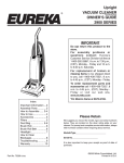
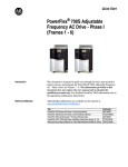
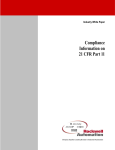
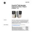
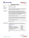
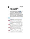
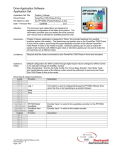
Quick Start
PowerFlex® 700S Drive
Introduction
This document is designed to guide you through the basic steps needed to
install, start-up and program the PowerFlex 700S Drive. The information
provided does not replace the user manual and is intended for qualified
personnel only. For detailed PowerFlex 700S information refer to the
following:
Title
PowerFlex 700S User Manual
PowerFlex 700S Reference Manual, Vol. 2
PowerFlex 700S Firmware Release Notes
Precautions
Publication
20D-UM001
PFlex-RM-002
20D-RN004
Available...
www.theautomationbookstore
.com
Class 1 LED Product
!
ATTENTION: Hazard of permanent eye damage exists when
using optical transmission equipment. This product emits intense
light and invisible radiation. Do not look into module ports or
fiber optic cable connectors.
General Precautions
!
!
!
ATTENTION: This drive contains ESD (Electrostatic
Discharge) sensitive parts and assemblies. Static control
precautions are required when installing, testing, servicing or
repairing this assembly. Component damage may result if ESD
control procedures are not followed. If you are not familiar with
static control procedures, reference A-B publication 8000-4.5.2,
“Guarding Against Electrostatic Damage” or any other
applicable ESD protection handbook.
ATTENTION: An incorrectly applied or installed drive can
result in component damage or a reduction in product life.
Wiring or application errors such as under sizing the motor,
incorrect or inadequate AC supply, or excessive surrounding air
temperatures may result in malfunction of the system.
ATTENTION: Only qualified personnel familiar with the
PowerFlex 700S Drive and associated machinery should plan or
implement the installation, start-up and subsequent maintenance
of the system. Failure to comply may result in personal injury
and/or equipment damage.
2
PowerFlex® 700S Drive
!
!
!
!
EMC Instructions
ATTENTION: To avoid an electric shock hazard, verify that the
voltage on the bus capacitors has discharged before performing
any work on the drive. Measure the DC bus voltage at the +DC &
–DC terminals of the Power Terminal Block (refer to Chapter 1
in the PowerFlex 700S User Manual for location). The voltage
must be zero.
ATTENTION: Risk of injury or equipment damage exists. DPI
or SCANport host products must not be directly connected
together via 1202 cables. Unpredictable behavior can result if
two or more devices are connected in this manner.
ATTENTION: Risk of injury or equipment damage exists.
Parameters 365 [Encdr0 Loss Cnfg] - 394 [VoltFdbkLossCnfg]
let you determine the action of the drive in response to operating
anomalies. Precautions should be taken to ensure that the settings
of these parameters do not create hazards of injury or equipment
damage
ATTENTION: Risk of injury or equipment damage exists.
Parameters 383 [SL CommLoss Data] - 392 [NetLoss DPI Cnfg]
let you determine the action of the drive if communications are
disrupted. You can set these parameters so the drive continues to
run. Precautions should be taken to ensure the settings of these
parameters do not create hazards of injury or equipment damage.
CE Conformity
Conformity with the Low Voltage (LV) Directive and Electromagnetic
Compatibility (EMC) Directive has been demonstrated using harmonized
European Norm (EN) standards published in the Official Journal of the
European Communities. PowerFlex Drives comply with the EN standards
listed below when installed according to the User and Reference Manual.
Declarations of Conformity are available online at:
http://www.ab.com/certification/ce/docs.
Low Voltage Directive (73/23/EEC)
• EN50178 Electronic equipment for use in power installations.
EMC Directive (89/336/EEC)
• EN61800-3 Adjustable speed electrical power drive systems Part 3:
EMC product standard including specific test methods.
PowerFlex® 700S Drive
3
General Notes
• If the adhesive label is removed from the top of the drive, the drive must
be installed in an enclosure with side openings less than 12.5 mm (0.5
in.) and top openings less than 1.0 mm (0.04 in.) to maintain compliance
with the LV Directive.
• The motor cable should be kept as short as possible in order to avoid
electromagnetic emission as well as capacitive currents.
• Use of line filters in ungrounded systems is not recommended.
• PowerFlex drives may cause radio frequency interference if used in a
residential or domestic environment. The user is required to take
measures to prevent interference, in addition to the essential
requirements for CE compliance listed below, if necessary.
• Conformity of the drive with CE EMC requirements does not guarantee
an entire machine or installation complies with CE EMC requirements.
Many factors can influence total machine/installation compliance.
• PowerFlex drives can generate conducted low frequency disturbances
(harmonic emissions) on the AC supply system. More information
regarding harmonic emissions can be found in the PowerFlex Reference
Manual, Vol. 2.
Essential Requirements for CE Compliance
Conditions 1-6 listed below must be satisfied for PowerFlex drives to meet
the requirements of EN61800-3.
1. Standard PowerFlex 700S CE compatible Drive.
2. Review important precautions/attentions statements throughout this
document before installing drive.
3. Grounding as described on page 1-4 of the user manual.
4. Output power, control (I/O) and signal wiring must be braided, shield
cable with a coverage of 75% or better, metal conduit or equivalent
attenuation.
5. All shielded cables should terminate with proper shielded connector.
6. Conditions in Table A.
Frame
Table A PowerFlex 700S EN61800-3 EMC Compatibility
1
2
3
4
5
6
Second Environment
Restrict Motor Cable to 30 m
(98 ft.)
Any Drive and Option
✔
✔
✔
✔
✔
✔
First Environment
Restricted Distribution
Refer to
PowerFlex Reference Manual,
Vol. 2
4
PowerFlex® 700S Drive
Mounting Clearances
Figure 1 Minimum Mounting Clearance Requirements
101.6mm
(4.0 in.)
No Adhesive Label
(see below)
50.8mm (2.0 in)
101.6mm
(4.0 in.)
50.8mm (2.0 in)
101.6mm
(4.0 in.)
With Adhesive Label
(see below)
101.6mm
(4.0 in.)
Refer to the PowerFlex Reference
Manual, Vol. 2 for detailed
dimension information
Operating Temperatures
PowerFlex 700S drives are designed to operate in a surrounding air
temperature range of 0° to 40° C. To operate the drive in installations with
surrounding air temperature between 41° and 50° C, remove the adhesive
label affixed to the top of the drive enclosure.
Important: Removing the adhesive label from the drive changes the NEMA
enclosure rating from Type 1 to Open type.
The following are the PowerFlex 700S dimensions.
Table B PowerFlex 700S Frames
AC Input
208/240
400V
ND
ND HP HD HP kW
1 2
1.5
7.5
3
2
11
5
3
–
7.5
5
–
2 10
7.5
15
–
–
18.5
3 15
10
22
20
15
30
–
–
37
4 25
20
45
30
25
–
5 40
30
55
50
40
–
6 60
50
75
75
60
90
–
–
110
Frame
Dimensions
480V
HD
kW
5.5
7.5
–
–
11
15
18.5
22
30
37
–
45
–
55
75
90
ND HP
10
15
–
–
20
25
30
40
50
60
–
75
100
125
150
–
600V
HD HP
7.5
10
–
–
15
20
25
30
40
50
–
60
75
100
125
–
ND HP
10
15
–
–
20
25
30
40
50
60
–
75
100
–
–
–
HD HP
7.5
10
–
–
15
20
25
30
40
50
–
60
75
–
–
–
DC Input
540V
650V
ND HP
7.5
11
–
–
15
18.5
22
30
37
45
–
55
–
75
90
110
ND HP
10
15
–
–
20
25
30
40
50
60
–
75
100
125
150
–
HD HP
5.5
7.5
–
–
11
15
18.5
22
30
37
–
45
–
55
75
90
HD HP
7.5
10
–
–
15
20
25
30
40
50
–
60
75
100
125
–
PowerFlex® 700S Drive
5
Figure 2 PowerFlex 700S Frame 1-3 (Frame 1 Shown)
A
12.5 (0.49)
D
C
7.0 (0.28) typ
B
E
7.0 (0.28) typ
7.0 (0.28)
D
Frame
Dimensions are in millimeters and (inches)
1
2
3
A
200.0 (7.87)
285.0 (11.22)
285.0 (11.22)
B
389.0 (15.31)
389.0 (15.31)
564.0 (22.20)
Weight ➊ kg
(lbs.)
Drive
C
D
E
202.8 (7.98) 175.0 (6.89) 375.0 (14.76) 11.3 (24.92)
202.7 (7.98) 250.0 (9.84) 375.0 (14.76) 18.4 (40.57)
202.7 (7.98) 250.0 (9.84) 550.0 (21.65) 26.6 (58.65)
➊ Weights include HIM, DriveLogix controller with ControlNet daughtercard, Hi-Resolution Encoder Option,
and 20-COMM-C ControlNet adapter
6
PowerFlex® 700S Drive
Figure 3 PowerFlex 700S Bottom View Dimensions, Frame1 & 2
Frame 1
25.5
(1.00)
173.5 (6.83)
152.5 (6.00)
132.5 (5.22)
72.5 (2.85)
190.4
(7.50)
187.9
(7.40)
136.1
(5.36)
108.0 (4.25)
135.0 (5.31)
140.9 (5.55)
161.0 (6.34)
Frame 2
22.4 (0.88) Dia.
2 Places
187.6
(7.39)
160.3
(6.31)
153.7
(6.05)
114.9
(4.52)
65.0 (2.56)
104.3 (4.11)
122.2 (4.81)
137.7 (5.42)
Dimensions are in millimeters and (inches)
171.0 (6.73)
201.4 (7.93)
242.4 (9.54)
28.7 (1.13) Dia.
3 Places
PowerFlex® 700S Drive
Figure 4 PowerFlex 700S Frame 3 Bottom View Dimensions
Frame 3 - All Drives, except 50 HP, 480 V (37 kW, 400V)
170.3 (6.70)
159.7 (6.29)
37.3 (1.47) Dia.
2 places
22.2 (0.87) Dia.
28.7 (1.13) Dia.
2 places
167.9
(6.61)
153.9
(6.06)
162.9
(6.41)
187.3
(7.37)
130.5
(5.14)
87.7 (3.45)
94.0 (37.0)
131.0 (5.16)
162.0 (6.38)
202.2 (7.96)
252.0 (9.92)
Frame 3 - 50 HP, 480V (37 kW, 400V) Normal Duty Drive
34.9 (1.37) Dia.
2 Places
170.3 (6.70)
159.7 (6.29)
28.7 (1.13) Dia.
2 Places
46.7 (1.84) Dia.
2 Places
167.9
(6.61)
162.9
(6.41)
130.5
(5.14)
87.7 (3.45)
94.0 (3.70)
131.0 (5.16)
202.2 (7.96)
Dimensions are in millimeters and (inches)
252 (9.92)
187.3
(7.37)
7
8
PowerFlex® 700S Drive
Figure 5 PowerFlex 700S Frame 4 Dimensions
A
D
13.0 (0.55)
7.0 (0.27) 2 Places
15.1 (0.59)
7.5 (0.30)
C
369.5 (14.53)
348.9 (13.76)
B
E
8.0 (0.31)
Lifting Holes 3 Places
4 Places
22.2 (0.87) Dia.
28.7 (1.13) Dia.
2 Places
76.0 (2.99)
65.3 (2.57)
8.0
(0.31)
47.0 (1.85) Dia.
2 Places
54.1 (2.13) Dia.
2 Places
189.7
(7.47)
177.9
(7.00)
157.9
(6.21)
141.9
(5.59)
105.1
(4.14)
65.0 (2.56)
26.8 (1.06)
36.8 (1.45)
51.5 (2.03)
63.8 (2.51)
Dimensions are in millimeters and (inches)
112.8 (4.44)
180.8 (7.12)
Approx. Weight ➊ kg (lbs.)
Frame A (Max.)
B
C (Max.)
D
E
Drive
Drive & Packaging
4
758.8 (29.9)
201.8 (7.94)
192.0 (7.56)
741.7 (29.2)
28.4 (62.5)
29.03 (63.9)
220.8 (8.69)
➊ Weights include HIM and Standard I/O.
PowerFlex® 700S Drive
9
Figure 6 PowerFlex 700S Frame 5 Dimensions
369.4 (14.54)
70.1 (2.76)
225.0 (8.86)
6.50 (0.26)
41.9 (1.65)
6.50 (0.26)
7.5 (0.30)
271.1 (10.57)
7.5 (0.30)
369.0 (14.53)
644.5 (25.37)
Overall
Height
75 HP
Frame 5
349.5 (13.76)
625.0 (24.61)
689.6 (27.15)
Overall
Height
100HP
Frame 5
6.50 (0.26)
Conduit Box
NOT Present
On 75 HP Frame 5
308.9 (12.16)
Frame 5 - 75 HP, 480 V (55kW, 400V)
169.0 (6.65)
158.2 (6.23)
34.9 (1.37) Dia.
2 Places
Frame 5 - 100 HP, 480 V (55kW, 400V)
22.2 (0.87) Dia.
2 Places
107.6 (4.24)
96.9 (3.81)
62.7 (2.47) Dia.
2 Places Removable Junction Box
62.7 (2.47) Dia.
2 Places
241.9
(9.52)
229.5
(9.04)
220.0
(8.66)
184.0
(7.24)
159.0
(6.26)
96.0
(3.77)
241.9
(9.52)
223.5
(8.80)
188.5
(7.42)
184.3
(7.26)
153.7
(6.05)
96.0
(3.78)
65.0 (2.56)
93.0 (3.66)
110.0 (4.33)
65.0 (2.56)
93.0 (3.66)
109 (4.29)
150.0 (5.91)
215.0 (8.46)
280.0 (11.02)
320.0 (12.60)
131.4 (5.17)
193 (7.60)
297.3 (11.70)
Dimensions are in millimeters and (inches)
Frame
5
34.9 (1.37) Dia.
22.2 (0.87) Dia.
2 Places
A
308.9(12.16)
B
644.5(25.37)
➊ Weights include HIM and Standard I/O.
C
275.4(10.84)
D
225.0(8.86)
E
625.0(24.61)
Approx Weight ➊ kg (lbs.)
37.19 (82)
10
PowerFlex® 700S Drive
Figure 7 PowerFlex 700S Frame 6 Dimensions
8.5 (0.33)
466.7 (18.38)
A
6.50 (0.26)
15.5 (0.61) 2 Places
8.0 (0.31)
18.0 (0.71)
Detail
11.5 (0.45)
360.6 (14.20)
D
C
369.0 (14.53)
349.5 (13.76)
E
B
8.5 (0.33)
Lifting Holes - 4 Places
12.7 (0.50) Dia.
126.3
(4.97)
123.5 (4.86)
112.9 (4.44)
34.9 (1.37) Dia.
62.7 (2.47) Dia.
3 Places
22.2 (0.87) Dia.
4 Places
Removable Junction Box
275.5
(10.85)
219.0
(8.62)
242.0
(9.53)
222.3
(8.75) 148.5
(5.85)
116.6
(4.59)
151.8
(5.98)
185.4
(7.30)
67.3 (2.65)
114.4 (4.5)
119.4 (4.7)
136.4 (5.37)
197.4 (7.77)
297.4 (11.7)
347.4 (13.7)
Dimensions are in millimeters and (inches)
Frame A (Max.)
6
403.90 (15.90)
397.4 (15.6)
Approx. Weight ➊ kg (lbs.)
Drive
Drive and Packaging
B
C (Max.)
D
E
850.00 (33.46) 275.50 (10.85) 300.00 (11.81) 825.00 (32.48) 11.3 (24.92)
92.85 (202.50)
➊ Weights include HIM and Standard I/O.
PowerFlex® 700S Drive
Wiring Recommendations
11
Since most start-up difficulties are the result of incorrect wiring, take every
precaution to assure the wiring is correct. Read and understand all items in
this section before beginning installation.
!
ATTENTION: The following information is merely a guide for
proper installation. The Allen-Bradley Company cannot assume
responsibility for the compliance or the noncompliance to any
code, national, local or otherwise for the proper installation of this
drive or associated equipment. A hazard of personal injury and/or
equipment damage exists if codes are ignored during installation.
Power Cable Types Acceptable for 200-600 Volt Installations
!
ATTENTION: National Codes and standards (NEC, VDE, BSI
etc.) and local codes outline provisions for safely installing
electrical equipment. Installation must comply with
specifications regarding wire types, conductor sizes, branch
circuit protection and disconnect devices. Failure to do so may
result in personal injury and/or equipment damage.
General
A variety of cable types are acceptable for drive installations. For many
installations, unshielded cable is adequate, provided it can be separated
from sensitive circuits. As an approximate guide, allow a spacing of 0.3
meters (1 foot) for every 10 meters (32.8 feet) of length. In all cases, long
parallel runs must be avoided. Do not use cable with an insulation thickness
less than or equal to 15 mils (0.4mm/0.015 in.). See Table C on page 12.
Unshielded
THHN, THWN or similar wire is acceptable for drive installation in dry
environments provided adequate free air space and/or conduit fill rates
limits are provided. Do not use THHN or similarly coated wire in wet
areas. Any wire chosen must have a minimum insulation thickness of 15
Mils and should not have large variations in insulation concentricity.
Shielded/Armored Cable
Shielded cable contains all of the general benefits of multi-conductor cable
with the added benefit of a copper braided shield that can contain much of
the noise generated by a typical AC Drive. Strong consideration for shielded
cable should be given in installations with sensitive equipment such as
weigh scales, capacitive proximity switches and other devices that may be
affected by electrical noise in the distribution system. Applications with
large numbers of drives in a similar location, imposed EMC regulations or a
high degree of communications/networking are also good candidates for
shielded cable.
12
PowerFlex® 700S Drive
Shielded cable may also help reduce shaft voltage and induced bearing
currents for some applications. In addition, the increased impedance of
shielded cable may help extend the distance the motor can be located from
the drive without the addition of motor protective devices such as terminator
networks. Refer to Reflected Wave in Wiring and Grounding Guidelines for
PWM AC Drives, publication DRIVES-IN001.
Consideration should be given to all of the general specifications dictated by
the environment of the installation, including temperature, flexibility,
moisture characteristics and chemical resistance. In addition, a braided
shield should be included and specified by the cable manufacturer as having
coverage of at least 75%. An additional foil shield can be greatly improve
noise containment.
A good example of recommended cable is Belden® 295xx (xx determines
gauge). This cable has 4 XLPE insulated conductors with a 100% coverage
foil and an 85% coverage copper braided shield (with drain wire)
surrounded by a PVC jacket.
Other types of shielded cable are available, but the selection of these types
may limit the allowable cable length. Particularly, some of the newer cables
twist 4 conductors of THHN wire and wrap them tightly with a foil shield.
This construction can greatly increase the cable charging current required
and reduce the overall drive performance. Unless specified in the individual
distance tables as tested with the drive, these cables are not recommended
and their performance against the lead length limits supplied is not known.
Table C Recommended Shielded Wire
Location
Rating/Type
Description
Standard
(Option 1)
600V, 90° C (194° F)
XHHW2/RHW-2
Anixter
B209500-B209507,
Belden®
29501-29507, or
equivalent
Four tinned copper conductors with XLPE insulation.
Copper braid/aluminum foil combination shield and tinned
copper drain wire.
PVC jacket.
Standard
(Option 2)
Tray rated 600V, 90°
C (194° F) RHH/
RHW-2
Anixter OLF-7xxxxx or
equivalent
Three tinned copper conductors with XLPE insulation.
5 mil single helical copper tape (25% overlap min.) with three
bare copper grounds in contact with shield.
PVC jacket.
Class I & II; Tray rated 600V, 90°
Division I & II C (194° F) RHH/
RHW-2
Anixter 7V-7xxxx-3G
or equivalent
Three bare copper conductors with XLPE insulation and
impervious corrugated continuously welded aluminum armor.
Black sunlight resistant PVC jacket overall.
Three copper grounds on #10 AWG and smaller.
PowerFlex® 700S Drive
13
Figure 8 Power Terminal Block Location
Frame 1
Frames 3 & 4
Frame 2
➌
Optional
Communications
Module
Optional
Communications
Module
#10-#14 AWG
Torque to 7 in-lbs
PE B
PE A
BR1
DC+
75C Cu Wire
2
6 AWG [10MM ] Max.
12 IN. LBS.
1.4 N-M } TORQUE
DC–
➌
PE
U/T1
V/T2
BR1 B
V/T2 W/T3
➌
POWER
BR2
CONTROL
WIRE
STRIP
PE R/L1 S/L2 T/L3
WIRE
STRIP
BR1 BR2
75C Cu Wire
6 AWG [10MM2] Max.
75C Cu Wire
2
3 AWG [25MM ] Max.
16 IN. LBS.
1.8 N-M } TORQUE
12 IN. LBS.
1.4 N-M } TORQUE
AUX IN
+ –
AUX IN+ AUX OUT–
POWER
➊
DANGER
CONTROL
!
Use 75C Wire Only
BR1 BR2 DC+ DC- U/T1 V/T2 W/T3 R/L1 S/L2 T/L3
➊
W/T3
R/L1
S/L2
T/L3
SHLD
SHLD
PE
SHLD
SHLD
➋
➊
/
➋
➋
Frame 6
Frame 5
➋
Sin
gle
Th Phas
r
e
(deee-P
fau has
lt) e
Phase Selection
Jumper
➋
Optional
Communications
Module
Line Type
Spare
Spare
Optional
Communications
Module
➍
WIRE RANGE: 22-10 AWG (0.5-4 MM2)
TORQUE: 5.3 IN-LB (0.6 N-M)
STRIP LENGTH: 0.35 IN (9 MM)
9
17
GROUND TERMINAL RATINGS (PE)
➍
300 VDC EXT PWR SPLY TERM (PS+, PS-)
POWER TERMINAL RATINGS
WIRE RANGE: 14-1/0 AWG (2.5-35 MM2)
TORQUE: 32 IN-LB (3.6 N-M)
STRIP LENGTH: 0.67 IN (17 MM)
USE 75 C CU WIRE ONLY
WIRE RANGE: 6-1/0 AWG (16-35 MM2)
TORQUE: 44 IN-LB (5 N-M)
STRIP LENGTH: 0.83 IN (21 MM)
21
OUTPUT
INPUT AC
Fan Voltage 1
WIRE STRIP
➌
PS+
PS–
➌
22-10
AWG
5.3 IN-LB
(0.6 N-M)
BR2
BR1
DC+
DC–
USE 75 C COPPER WIRE ONLY, TORQUE 52 IN-LB (6 N-M)
690 Volt Tap
600 Volt Tap
480 Volt Tap
400 Volt Tap
➊
➊
1
Frame 5 & 6 utilize a transformer to match the input line voltage to the internal fan voltage.
If you line voltage is different then the voltage class specified on the drive nameplate, it
may be necessary to change the transformer taps. The taps are shown in the inserts of
frames 5 & 6.
Common Bus drives require user supplied 120V or 240V to power the cooling fans.
Power source is connected between “0V AC” and the terminal corresponding to your
source voltage (see common bus terminal blocks, page 15).
USE 75 C
COPPER WIRE
ONLY
TORQUE
52 IN-LB
(6 N-M)
T1
T2
T3
OUTPUT
L1
L2
L3
INPUT
Fan VA Rating - Common Bus Only
Frame Fan Voltage(120V or 240V)
5
6
100 VA
138 VA
PE
14
PowerFlex® 700S Drive
Table D Power Terminal Block Specifications
No.
➊
Name
Power Terminal Block
Frame
1
2
3
4
5
(75 HP)(2)
5
(100 HP)(2)
6
Wire Size Range(1)
Maximum
Minimum
Description
0.5 mm2
All power terminals
4.0 mm2
(10 AWG)
(22 AWG)
All power terminals
10.0 mm2
0.8 mm2
(6 AWG)
(18 AWG)
All power terminals
25.0 mm2
2.5 mm2
(3 AWG)
(14 AWG)
All power terminals
10.0 mm2
0.8 mm2
(6 AWG)
(18 AWG)
All power terminals
35.0 mm2
10 mm2
(1/0 AWG)
(8 AWG)
2.5 mm2
R, S, T, BR1, 2, DC+, DC-, U, V 35.0 mm2
(1/0 AWG)
(14 AWG)
and W
PE
35.0 mm2
16.0 mm2
(1/0 AWG)
(6 AWG)
16.0 mm2
R, S, T, DC+, DC-, U, V and W 70.0 mm2
(3/0 AWG)
(4 AWG)
BR1, 2,
35.0 mm2
2.5 mm2
(1/0 AWG)
(14 AWG)
PE
35.0 mm2
16.0 mm2
(1/0 AWG)
(6 AWG)
All power terminals
70.0 mm2
2.5 mm2
(250 MCM)
(14 AWG)
Torque
Maximum
1.7 N-m
(15 lb.-in.)
1.7 N-m
(15 lb.-in.)
3.6 N-m
(32 lb.-in.)
1.7 N-m
(15 lb.-in.)
4.0 N-m
(24 lb.-in.)
3.6 N-m
(32 lb.-in.)
5 N-m
(44 lb.-in.)
15 N-m
(133 lb.-in.)
3.6 N-m
(32 lb.-in.)
5 N-m
(44 lb.-in.)
6 N-m
(52 lb.-in.)
Recommended
0.8 N-m
(7 lb.-in.)
1.4 N-m
(12 lb.-in.)
1.8 N-m
(16 lb.-in.)
1.4 N-m
(12 lb.-in.)
4.0 N-m
(24 lb.-in.)
3.6 N-m
(32 lb.-in.)
5 N-m
(44 lb.-in.)
15 N-m
(133 lb.-in.)
3.6 N-m
(32 lb.-in.)
5 N-m
(44 lb.-in.)
6 N-m
(52 lb.-in.)
➋
SHLD Terminal
1-6
Terminating point for wiring
shields
—
—
1.6 N-m
(14 lb.-in.)
1.6 N-m
(14 lb.-in.)
➌
AUX Terminal Block
1-4
Auxiliary Control Voltage (3)
PS+, PS-
1.3 mm2
(16 AWG)
4.0 mm2
(10 AWG)
4.0 mm2
(10 AWG)
0.2 mm2
(24 AWG)
0.5 mm2
(22 AWG)
0.5 mm2
(22 AWG)
—
—
0.6 N-m
(5.3 lb.-in.)
0.6 N-m
(5.3 lb.-in.)
0.6 N-m
(5.3 lb.-in.)
0.6 N-m
(5.3 lb.-in.)
5-6
➍
Fan Terminal Block
(Common Bus Only)
5-6
User Supplied Fan Voltage
0V AC, 240V AC, 120V AC
(1) Maximum/minimum sizes that the terminal block will accept - these are not recommendations.
(2) Not all terminals present on all drives.
(3) External control power:
UL Installation - 300V DC, ±10%, Non UL Installation - 270-600V DC, ±10%.
Frame 1-6, 100 W
Figure 9 Power and Ground Wiring
R
(L1)
S
(L2)
T
(L3)
PE
U
(T1)
V
(T2)
W
(T3)
DC
+
DC
–
BR1
BR2
Required
Input Fusing
Required Branch
Circuit Disconnect
Important Common Bus (DC Input) Application Notes
1. If drives without internal precharge are used (Frames 5 & 6 only), then:
a) precharge capability must be provided in the system to guard against possible damage, and
b) disconnect switches Must Not be used between the input of the drive and a common DC bus without the use of an external
precharge device.
2. If drives with internal precharge (Frames 0-6) are used with a disconnect switch to the common bus, then:
a) an auxiliary contact on the disconnect must be connected to a digital input of the drive. The corresponding input (parameter
361-366) must be set to option 30, “Precharge Enable.” This provides the proper precharge interlock, guarding against possible
damage to the drive when connected to a common DC bus.the drive must have firmware version 2.002 or above (Standard &
Vector Control).
PowerFlex® 700S Drive
Figure 10 Power Terminal Block
BR1
BR2
DC+
DC–
PE
Frame 2
BR1 BR2 DC+ DC– PE
Frame 1
U (T1)
V (T2)
W (T3)
R (L1)
S (L2)
T (L3)
U V W R S T
(T1) (T2) (T3) (L1) (L2) (L3)
Frame 3
BR1 BR2 DC+ DC– U V W R S
T
(T1) (T2) (T3) (L1) (L2) (L3)
BR1/
BR2 DC+ DC+ DC– U/T1 V/T2 W/T3
PS–
PE
PE
R/L1 S/L2 T/L3
Frame 5 - 75 HP, Normal Duty
AC Input
PS+
BR2
BR1/
DC+
DC+
DC–
U/T1
V/T2
R/L1
W/T3
PE
S/L2
T/L3
PE
PS–
Frame 5 - 100 HP, Normal Duty
AC Input
PS+
BR1*/
BR2* DC+ DC+ DC–
PS–
U/T1 V/T2 W/T3
0 240
VAC VAC
PE
PE
Frame 5 - 75 HP, Normal Duty
650V DC Iput
120
VAC
PS+
Precharge Resistor Fuse – FWP-15A14F
(Common Bus Drives w/Precharge Only)
BR1*/
BR2* DC+
PS–
DC+
DC–
U/T1
V/T2
W/T3
0 240
PEVAC VAC
PE
Frame 5 - 100 HP, Normal Duty
650V DC Input
120
VAC
PS+
22-10
AWG
5.3 IN-LB
(0.6 N-M)
BR2
BR1
DC+
Common Mode Capacitor
& MOV Jumpers
DC–
Common Mode Capacitor
PS+
PS–
WIRE STRIP
PS+
PS–
WIRE STRIP
Precharge Resistor Fuse – FWP-15A14F
(Common Bus Drives w/Precharge Only)
& MOV Jumpers
22-10
AWG
5.3 IN-LB
(0.6 N-M)
BR2
BR1
DC+
DC–
Input Filter Capacitor
USE 75 C COPPER WIRE ONLY, TORQUE 52 IN-LB (6 N-M)
USE 75°C COPPER WIRE ONLY, TORQUE 52 IN-LB (6 N-M)
Precharge Resistor Fuse – FWP-15A14F
(Common Bus Drives w/Precharge Only)
V
T2
W
T3
PE
OUTPUT
PE
R
L1
S
L2
T
L3
TORQUE
52 IN-LB
(6 N-M)
U
T1
V
T2
W
T3
PE
OUTPUT
INPUT
Frame 6 - 150 HP, Normal Duty
480V AC Input
Shaded terminals (BR1 & BR2) will only be present on drives ordered with the Brake Option.
PE
22-10 AWG
5.3 IN-LB
(0.6 N-M)
0V AC
1-PHASE
TORQUE
52 IN-LB
(6 N-M)
USE 75 C
COPPER WIRE
ONLY
U
T1
FAN
INPUT
USE 75°C
COPPER WIRE
ONLY
0 VAC
120 VAC
240 VAC
Input Filter Capacitor
120V AC
Frame 6 - 150 HP, Normal Duty
650V DC Input
240V AC
15
16
PowerFlex® 700S Drive
Table E Terminal Block Designations
Terminal
BR1
BR2
DC+
DC–
PE
U
V
W
R
S
T
Description
DC Brake (+)
DC Brake (–)
DC Bus (+)
DC Bus (–)
PE Ground
Motor Ground
U (T1)
V (T2)
W (T3)
R (L1)
S (L2)
T (L3)
Notes
Dynamic Brake Resistor Connection (+)
Dynamic Brake Resistor Connection (–)
DC Input Power or Dynamic Brake Chopper
DC Input Power or Dynamic Brake Chopper
Refer to Figure 9 on page 14 for location on 3 Frame drives
Refer to Figure 8 on page 13 for location on 3 Frame drives
To motor
To motor
To motor
AC Line Input Power
AC Line Input Power
AC Line Input Power
Control Wiring
Important points to remember about I/O wiring:
• Always use copper wire.
• Wire with an insulation rating of 600V or greater is recommended.
• Control and signal wires should be separated from power wires by at
least 0.3 meters (1 foot).
Important: I/O terminals labeled “(–)” or “Common” are not referenced to
earth ground and are designed to greatly reduce common mode
interference. Grounding these terminals can cause signal noise.
Recommended Control Wire
Type
Signal
Digital I/O
EMC
Compliance
Wire Type(s)
Analog I/O Belden 8760/9460(or
equiv.)
Description
0.750 mm2 (18AWG),
twisted pair, 100% shield
with drain (1).
Belden 8770(or equiv.)
0.750 mm2 (18AWG), 3
cond., shielded for remote
pot only.
Encoder/ Less than or equal to 30 m 0.196 mm2 (24AWG),
Pulse I/O (98 ft.) – Belden 9728 (or individually shielded.
equiv.)
Greater than 30 m (98 ft.) – 0.750 mm2 (18AWG),
twisted pair, shielded.
Belden 9773(or equiv.)
Unshielded Per US NEC or applicable –
national or local code
0.750 mm2 (18AWG), 3
Shielded Multi-conductor shielded
cable such as Belden
conductor, shielded.
8770(or equiv.)
Refer to EMC Instructions for details.
Insulation
Rating
300V,
75-90° C
(167-194°
F), Minimum
300V,
60° C
(140° F),
Minimum
(1) If the wires are short and contained within a cabinet which has no sensitive circuits, the use of shielded wire
may not be necessary, but is always recommended.
PowerFlex® 700S Drive
17
Wiring the Main Control Board I/O Terminals
Terminal blocks TB1 and TB2 contain connection points for all inputs,
outputs and standard encoder connections. Both terminal blocks reside on
the Main Control Board.
Remove the terminal block plug from the socket, and make connections.
TIP: Remember to route wires through the sliding access panel at the
bottom Control Assembly.
Reinstall the plug, when wiring is complete. The terminal blocks have keys,
which make it difficult to insert a terminal plug into the wrong socket.
Table F Control & Encoder Terminal Block Specifications
Name
Frame Description
I/O & Encoder 1, 2, 3, 5 Signal & Encoder
Blocks
power connections
Wires Size Range(1)
Maximum
Minimum
1.5 mm2
.14 mm2
(16 AWG)
(28 AWG)
Torque
Maximum
.25 N-m
(2.2 lb.-in.)
Recommended
.22 N-m
(1.9 lb.-in.)
(1) Maximum/minimum sizes the terminal block will accept - these are not recommendations.
Figure 1 Main Control Board I/O Terminal Locations
TB1 - Row B (Bottom)
TB2
TB1
TB1 - Row T (Top)
TB2 - Row B (Bottom)
TB2 - Row T (Top)
18
PowerFlex® 700S Drive
Signal
Power Supply 24V DC Return (-)
Power Supply 24V DC (+)
Logic Common
T8
Digital Input #1
9
T7
Enable Input
T6
Digital Output #1
T5
Digital Output #2
T4
T3
T2
T1
Digital Output Return
Thermistor Input
Thermistor Input Return
Thermistor Shield
T1
2
3
4
5
6
7
8
Default = Precharge
Description
Power and common for pre charge
and enable inputs.(1) Inputs may
sink or source.(2)
Rating: 100 mA maximum.
For common DC bus drives. Must
be high, for drive to complete the
pre charge cycle.
Load: 20 mA at 24V DC.
Must be high for drive to run.
Load: 20 mA at 24V DC.
24V DC open collector (sinking
logic) output.
Rating: 25 mA maximum.
24V DC open collector (sinking
logic) output.
Rating: 25 mA maximum.
Return for Digital outputs 1 and 2.
Used only in FOC2 mode with
approved motor for temperature
adaptation.
Related
Parameter
Terminal
T11
T10
T9
10
11
Table G TB1 - Row T (Top) Terminals
824, 838,
829, 826,
827, 828
824, 825
843, 844,
824
845, 846,
824
485
(1) The drive’s 24V DC power supply supports only on-board digital inputs. Do not use it to power circuits outside of the drive.
(2) Refer to wiring examples of sinking and sourcing outputs.
Signal
Analog Input #1 (-)
Analog Input #1 (+)
B9
Analog Input Shield
B8
B7
Analog Input #2 (-)
Analog Input #2 (+)
B6
B5
Analog Output #1 (+)
Analog Output #1 Return (-)
B4
Analog Output Shield
B3
B2
Analog Output #2 (+)
Analog Output #2 Return (-)
B1
Analog Output Shield
B1
2
3
4
5
6
7
8
9
10
11
Terminal
B11
B10
Description
+/-10.0V DC or +/-1.0V DC bipolar,
differential input. (1), 13 bit + sign,
20k ohm input impedance
Optional connection point for
analog input shield. (2)
+/-10.0V DC or +/-1.0V DC bipolar,
differential input. (1), 13 bit + sign,
20k ohm input impedance
+/-10.0V DC bipolar, differential
output, 11 bit + sign, 2k ohm
minimum load
Optional connection point for
analog output shield. (2)
+/-10.0V DC bipolar, differential
output, 11 bit + sign, 2k ohm
minimum load
Optional connection point for
analog shields.
Related
Parameter
Table H TB1 - Row B (Bottom) Terminals
800, 801,
802, 803,
804, 805
806, 807,
808, 809,
810, 811
814, 815,
816, 817,
812, 818
819, 820,
821, 822,
813, 823
(1) Refer to Analog Input Settings in the PowerFlex 700S User Manual for necessary dip switch settings.
(2) Analog shields should connect to common at the signal source, if possible. Shields for signals from ungrounded devices, such as analog
tachometers, should connect to an analog shield terminal point at the drive.
PowerFlex® 700S Drive
19
Table I TB2 - Row T (Top) Terminals
3
4
6
5
7
8
9 10 11 12 13
Related
Parameter
T1 2
Terminal
T13
T12
T11
T10
T9
T8
T7
T6
T5
Signal
Encoder Signal A
Encoder Signal Not A
Encoder Signal B
Encoder Signal Not B
Encoder Signal Z
Encoder Signal Not Z
Shield
Digital Input #2
Digital Input #2 Return
Description
222, 232,
Primary encoder interface. 5 or 12V DC switch
selectable (1), Nominal current draw per channel @ 233, 234,
231, 230,
12V DC 45 mA, @5V DC 32 mA
236, 237.
238, 235
T4
T3
Digital Input #3
Digital Input #3 Return
High speed 12-24V DC sinking digital input.
T2
T1
Power Supply +12V DC (A) (+)
Power Supply +12V DC Return (A) (-)
12V DC power supply for primary encoder interface
and high speed inputs. Rating 300 mA(2)
Connection point for encoder shield.
High speed 12-24V DC sinking digital input.
824, 839,
833, 830,
831, 832
824, 840,
837, 834,
835, 836
(1) Refer to Encoder Input Settings in the PowerFlex 700S User Manual for necessary dip switch settings.
(2) This power supply supports only the primary encoder interface and digital inputs. Do not use it to power circuits outside of the drive.
Table J TB2 - Row B (Bottom) Terminals
Terminal
B13
B12
B11
B10
B9
B8
B7
B6
B5
B4
B3
B2
B1
3
4
Signal
Encoder Signal A
Encoder Signal Not A
Encoder Signal B
Encoder Signal Not B
Encoder Signal Z
Encoder Signal Not Z
Shield
Unused
Relay Output
Relay Output Return
Unused
Power Supply +12V DCDC (B) (+)
Power Supply +12V DC Return (B) (-)
5
6
7
8
9 10 11 12 13
Description
Secondary encoder interface. 5 or 12V DC switch
selectable (1), Nominal current draw per channel @
12V DC 45 mA, @5V DC 32 mA
Related
Parameter
B1 2
222, 243,
244, 242,
241, 240,
246, 247,
248, 245
Connection point for encoder shield.
Relay contact output.
824, 841,
Rating: 5A @ 24V DC Resistive, 2A 24V DC Inductive 842
12V DC power supply for secondary encoder
interface. Rating 300 mA(2)
(1) Refer to Encoder Input Setting in the PowerFlex 700S User Manual for necessary dip switch settings.
(2) This power supply supports only the secondary encoder interface. Do not use it to power circuits outside of the drive
20
PowerFlex® 700S Drive
SynchLink
SynchLink provides high-speed synchronization and communication
between multiple PowerFlex 700S drives (or other products with SynchLink
capability).
Refer to the SynchLink Design Guide (1756-TD008) when planning and
connecting the SynchLink network.
Class 1 LED Product
!
ATTENTION: Hazard of permanent eye damage exists when
using optical transmission equipment. This product emits intense
light and invisible radiation. Do not look into module ports or
fiber optic cable connectors.
Figure 11 SynchLink Connections
J8 (Transmit)
J9 (Receive)
Connect cables J8 (transmit) and J9 (receive) connectors on the bottom of
the Main Control Board. Push the plug into the socket until it produces an
audible click.
Important: Do not overtighten tie-wraps.
PowerFlex® 700S Drive
I/O Wiring Examples
21
This section provides basic information to wire the PowerFlex 700S.
Table K Digital Wiring Examples
The following definitions are used throughout this section:
Source
• Apply positive voltage through the device to the input or output.
• Connect the input or output common (return) directly to the power supply common.
Sink
• Apply the positive voltage directly to the input or output common (return).
• Connect the input or output to the power supply common through the device
Input/Output
Connection Example
Sourcing Input - using internal power supply
TB1 - Row T (Top)
11
Precharge
Precharge control is used in common bus configurations
and is not required for AC fed drives.
10
9
8
7
PRECHARGE
Digital Inputs used for
enable and precharge
control.
ENABLE
Default If this is not used the drive must
be re-programmed or use a
jumper between terminal #8 & 10
Fixed - If this is not
used a jumper must be
used between 7 & 10.
Note:
Sourcing Input - using external power supply
24V DC Supply supports only on-board
digital inputs. Do not use
TB1 - Row T (Top)
for circuits outside the
COMMON
(RETURN) +24V DC
drive.
9
8
7
If precharge control is not required, reprogram Par 838
[DigIn 1 Sel] to a value of zero or replace the contact
shown with a jumper from Terminal 8 to Terminal 10.
If precharge is needed, in sinking configuration, this
circuit must connect to 24V DC power for drive to
complete the precharge cycle.
Enable - In sourcing configuration, must connect to 24V
DC common for drive to run.
Precharge
Precharge control is used in common bus configurations
and is not required for AC fed drives.
If precharge control is not required, reprogram Par 838
[DigIn 1 Sel] to a value of zero
PRECHARGE
ENABLE
Auxiliary Outputs 24V DC outputs 25 mA
maximum per output
Required Parameter Changes
Enable - In sinking configuration, this circuit must
connect to 24V DC power for drive to run.
If precharge is needed, in sourcing configuration, must
connect to 24V DC common for drive to enter pre charge
cycle.
Digital Output 1 Indicating Alarm and Digital Output 2 Indicating Using DigOut 1 to annunciate an alarm:
Fault - in sourcing configuration
• Link the status word to the output control
Par 843 [DigOut 1 Data] (the destination) linked to
TB1 - Row T (Top)
Par 155 [Logic Status] (the source)
11
•
Select which bit activated the output
10
Par 844 [DigOut] / 1 Bit = 8 “alarm”
6
5
4
22
PowerFlex® 700S Drive
Input/Output
Auxiliary Output Relay contact output
Connection Example
Auxiliary Output - sourcing configuration
TB2 - Row B (Bottom)
EXTERNAL
24V DC
COMMON
(RETURN)
EXTERNAL 24V
POWER SUPPLY
4 5
Using Relay Out to annunciate “drive running:”
• Link the status word to the relay control
Par 841 [Relay Out Data] (the destination) linked to
Par 155 [Logic Status] (the source)
• Set Par 842 [Relay Out Bit] to a value of one, so that
Par 155 [Logic Status] / bit 1 “Running” will control
the output.
Running
12 - 24V DC Inputs
3-Wire Control, Non-Reversing - using internal power supply
Digital Inputs used for
Start/Stop 3-Wire
Control
TB2 - Row T (Top)
•
Par 839
Digital Input 2 Select = 1 “Normal Stop”
•
Par 840
Digital Input 3 Select = 2 “Start”
•
Par 153 [Control Option] / bit 8 (3WireControl) = 1
“3- wire control”
1 2 3 4 5 6
Use Digital Input 2 & 3 for 3-wire Start/Stop Control
Start
Stop
2 -Wire Control, Non-Reversing - using external power supply
Digital Inputs used for
Run/Stop 2-Wire Control (1)
Note: +12V and +24V
are also available from
TB1 Top 10 & 11.
TB2 - Row T (Top)
•
Par 839
Digital Input 2 Select = 3 (Run)
•
Par 153 [Control Option] / bit 8 (3WireControl) = 0
“2-wire control”
AND
Par 153 [Control Option] / bit 9 (2W CoastStop) = 0
“ramp stop”
or
Par 153 [Control Option] / bit 9 (2W CoastStop) = 1
“coast stop”
12 OR 24VDC
POWER SUPPLY
COMMON
(RETURN)
•
POWER
3 4 5 6
•
Run-Stop
Use Digital Input 2 for 2-wire Run/Stop Control
(1) See “Important” statement about the HIM on page 27.
PowerFlex® 700S Drive
23
Table L Analog Wiring Examples
Analog I/O
Connection Example
Analog Inputs
Analog Inputs - shield terminated at source
- +/-10V DC or +/-1.0V
DC (DIP switch setable)
TB1 - Row B (Bottom)
Terminate shields at the
analog source if analog
common is available
11
10
Used for Speed
Reference and Speed
Trim
#1
+
COMMON
(RETURN)
+
8
7
#2 Speed
Trim
COMMON
(RETURN)
Analog Outputs - +/
-10V DC
Speed
Reference
TB1 - Row B (Bottom)
Used to drive analog
meters displaying speed
and current
#1 Motor
Speed
6
+
Using Analog In2 as -10 to +10V speed trim @ 10%:
• Scale the input to .1V - 10%
Par 808 [Anlg ln2 Scale]=.01
• Send the data to the speed Reference parameter
Par 13 [Speed Ref2] (the destination) linked to Par
806 [Anlg ln2 Data] (the source)
• Select Ref 1 as the active speed ref and Ref2 as trim
[Speed Ref Sel] = 3
Using Analog Out 1, -10V to + 10V to meter Motor
RPM and direction:
• Send the data to the Analog Output
Par 815 [Anlg Out1 Real] (the destination) linked to
Par 300 [Motor Spd Fdbk] (the source)
• Scale the Output to the source parameter
Par 817 [Anlg Out1 Scale] = 175 (1750 Par 4 [Motor
NP RPM] / 10V)
-
5
4
Motor
#2 Current
3
2
Required Parameter Changes
Using Analog In1 as 0 - 10 V speed reference:
• Scale the Input to 1 V
Par 802 [Anlg ln1 Scale] =.1
• Send the data to the Speed Reference parameter
Par 10 [Speed Ref1] (the destination) linked to Par
800 [Anlg ln1 Data] (the source)
• Select Ref 1 as the active speed ref
Par 16 [Speed Ref Sel] = 1
• Par 153 [Control Option]\bit 0 = 0 (Unipolar Speed
Reference)
+
-
1
Using Analog Out 2, -10V to + 10V to meter Motor
Current:
• Send the data to the Analog Output
Par 820 [Anlg Out2 Real] (the destination) linked to
Par 308 [Output Current] (the source)
• Scale the Output to the source parameter
Par 822 [Anlg Out2 Scale] = xx (Par 2 [Motor NP FLA]
/ 10 V Output)
Table M Encoder Wiring Example
Input/Output
Connection Example
Primary Encoder - using internal power supply
Primary Encoder
Interface TB2 - Row T (Top)
Supports 12V DC
differential encoders with
internal power supply.
5V DC differential
encoders require
external power supply
and special jumper
settings.
1
2
7
8 9 10 11 12 13
Used as primary closed
loop speed feedback
POWER
COMMON
(RETURN)
Z Z B B A A
CASE GROUND
Required Parameter Changes
Using Encoder 0 as speed feedback:
• Par 222 [Motor Fdkbk Sel] = 0 (Encoder 0 = default)
• Par 232 [Encoder 0 PPR] = Pulses/Rev for installed
encoder
24
PowerFlex® 700S Drive
Start-Up Check List
This section describes how you start-up the PowerFlex 700S.
ATTENTION: Power must be applied to the drive to perform
the following start-up procedure. Some of the voltages present are
at incoming line potential. To avoid electric shock hazard or
damage to equipment, only qualified service personnel should
perform the following procedure. Thoroughly read and
understand the procedure before beginning. If an event does not
occur while performing this procedure, Do Not Proceed.
Remove Power including user supplied control voltages. User
supplied voltages may exist even when main AC power is not
applied to then drive. Correct the malfunction before continuing.
!
Before Applying Power to the Drive
❏ 1. Confirm that motor wires are connected to the correct terminals and are
secure.
❏ 2. Confirm that encoder wires are connected to the correct terminals and
are secure.
❏ 3. Confirm that all control inputs are connected to the correct terminals and
are secure.
❏ 4. Verify that AC line power at the disconnect device is within the rated
value of the drive.
❏ 5. Verify that control power voltage is correct.
The remainder of this procedure requires a HIM (Human Interface Module)
be installed. If an operator interface is not available, remote devices should
be used to start-up the drive.
PWR (Power)
4
DRIVE
DRIVE
1
ENABLE
SYNCHLINK
2
STS (Status)
3
PowerFlex® 700S Drive
25
Applying Power to the Drive
❏ 6. Apply AC power and control voltages to the drive. Examine the Power
(PWR) LED.
Steady Green
Power has been applied to the drive and no faults are present.
❏ 7. Examine the Status (STS) LED. Verify that it is flashing green. If it is not
in this state, check the following possible causes and take the necessary
corrective action.
Flashing Yellow
A run inhibit exists in the drive. Refer to Table N to correct the problem.
Table N Common Causes of a Pre-Start Alarm
Examine Par 156 - Run Inhibit Status
bit Description
1 No power is present at the Enable Terminal TB1 - T7
2, 3, 4 A stop command is being issued
Power loss event is in progress, indicating a loss of the AC
5
input voltage
Data supplied by the power structure EEprom is invalid or
6
corrupt.
7 Flash Update in Progress
Drive is expecting a Start Edge and is receiving a continuous
8
signal.
Drive is expecting a Jog Edge and is receiving a continuous
9
signal.
A conflict exists between the Encoder PPR programming (Par
10 232 or 242) and the encoder configuration for edge counts
(Par 233 or 243, bits 4 & 5).
The drive cannot precharge because a precharge input is
11
programmed and no signal is present.
Start input configured but stop not configured
Run input configured but control options do not match
Start input configured but control options do not match
Multiple inputs configured as Start or Run
12
Action
Apply the enable
Close all stop inputs
Restore AC power
Cycle power. If problem persists, replace the power structure.
Complete Flash Procedures
Open all start buttons and remove all start commands
Open all jog buttons and remove all jog commands
Verify encoder data and reprogram
Reprogram the input or close the precharge control contact.
Digital Configuration
Program Par 838-840 to include a stop button, rewire the drive
Program Par 153, Bit 8 to “0” (2 wire control)
Program Par 153, Bit 8 to “1” (3 wire control)
Reprogram Par 838-840 so multiple starts, multiple runs or any
combination do not exist
Multiple inputs configured as Jog1
Reprogram Par 838-840 so only (1) is set to Jog1
Multiple inputs configured as Jog2
Reprogram Par 838-840 so only (1) is set to Jog2
Multiple inputs configured as Fwd/Rev
Reprogram Par 838-840 so only (1) is set to Fwd/Rev
Invalid Feedback Device for Permanent Magnet Motor Control Set Par 222 to Value 5 (FB Opt Port0)
14
Flashing Red
A fault has occurred. Refer to Table O on page 26 for common start-up
faults and actions to correct the problem.
26
PowerFlex® 700S Drive
Table O Common Start-Up Faults
Fault
Encoder Loss
Motor Overload
Description
One of the following has occurred on an encoder:
• missing encoder (broken wire)
• quadrature error
• phase loss
A motor overload is pending.
Motor Poles Fault The poles of the motor do not match its rating.
Action
Reconnect encoder or replace encoder.
Enter correct motor nameplate full load amps. Par 2
[Motor NP FLA] or reduce excess load.
Enter correct motor nameplate RPM. Par 4 [Motor NP
RPM]
Steady Red
A fault has occurred. Cycle the power. If the light continues to be steady
red, replace the drive.
Alternately Flashing Red/Yellow
A non-resettable, terminal fault has occurred. The drive needs to be
replaced.
If any digital input is configured to Stop - CF (CF=Clear Faults) verify the
signal is present or the drive will not start. Refer to Chapter 4 in the
PowerFlex 700S User Manual for a list of potential digital input conflicts.
If a fault code appears, refer to Chapter 4 in the PowerFlex 700S User
Manual.
The STS LED should be flashing green at this point.
❏ 8. Proceed to Start-Up Routine.
PowerFlex® 700S Drive
27
Assisted Start-Up
This routine prompts you for information that is needed to start-up a drive
for most applications, such as line and motor data, commonly adjusted
parameters and I/O.
Important: This start-up routine requires a HIM. If the drive is configured for 2-wire
control, the HIM installed on the drive will also act as a 2-wire device. In
2-wire mode, the drive will start when the HIM “Start” is pressed and stop
when the HIM “Start” is released. The recommended mode of use for a
Start-Up Routine is 3-wire control, Parameter 153 [Control Options], Bit
8 set to “1”.
The assisted start-up routine asks simple yes or no questions and prompts
you to input required information. Access Assisted Start-Up by selecting
“Start-Up” from the Main Menu.
Step
Key(s)
Example LCD Displays
1. To exit the User Display screen Press Esc.
F
Stopped
0.0
Esc
Auto
RPM
0.0
0.0 Output
DC Bus V
1. In the Main Menu, use the Down Arrow to scroll to
“Start Up”.
2. Press Enter.
TIP: Throughout the Start-Up Routine
many screens have more selections than
shown. Use the arrow keys to scroll
through all the menu options.
F
Stopped
0.0
C
Auto
RPM
Main Menu:
0.0
Diagnostics
Parameter
Device Select
1. Follow the instructions on the screen to complete the
Start-Up.
PowerFlex 700S
Start-Up
The Start-Up
routine sets up
0.0 for
the drive
Diagnostics
basic operation.
Push Enter.
TIP: If using a HIM the following functions are not available.
• Alt-Man
• Alt-Lang
• Alt-SMART
28
PowerFlex® 700S Drive
PowerFlex 700S
Start-Up
Down 1 level or Select
Back 1 level or 1 selection
Scroll all choices
Esc
Feedback
Configuration
Motor Control
Motor Data
Power Circuit Test
Direction Test
Select Motor Control
Mode
Select DB Resistor
Enter Motor NP Data
Power & Units
FLA
Volts
Hertz
RPM
Poles
Setup / Select
Encoder
Resolver
Hi-Res Encoder
Linear Sensor
Diagnostic Check for
Drive Power Circuit
Verify Direction
Motor Tests
Inertia Measure
Speed Limits
Speed Control
Start / Stop / I/O
Field Oriented
Control: Measure
Stator Resistance,
Leakage Inductance,
Magnetizing
Inductance
PMag Motor: Encoder
Offset, Stator
Resistance, Stator
Inductance, Back EMF
Measure System
Inertia
Select Direction
Control
Set FWD, REV and
ABS Speed Limits
Select Sources For All
Speed References
Configure:
Digital Inputs, Digital
Outputs, Analog
Inputs, Analog Outputs
(1)
Done /
Exit
(1)See “Important” statement about the HIM on page 27
Note: In 2-wire mode, the drive will start when the HIM “Start” is pressed
and stop when the HIM “Start” is released. The recommended mode of use
for the Start-Up Rountine is 3-wire control, Parameter 153 [Control
Options], Bit 8 set to “1”.
PowerFlex® 700S Drive
Status Indicators
Table P Drive Status Indicator Descriptions
#
Name
Color
State
Description
➊
PWR
(Power)
STS
(Status)
Green
Steady
Illuminates when power is applied to the drive.
Green
Flashing
Steady
Flashing
Control Assembly
Communications
Control
Power Structure
➋
DRIVE
29
➌
PORT
MOD
NET A
NET B
Drive ready, but not running & no faults are present.
Drive running, no faults are present.
Yellow
A type 2 (non-configurable) alarm condition exists, drive continues to
run.
Steady
A type 1 (user configurable) alarm condition exists, but drive
continues to run.
Red
Flashing
A fault has occurred.
Steady
A non-resettable fault has occurred.
Red /
Flashing
The drive is in flash recovery mode. The only operation permitted is
Yellow Alternately flash upgrade.
Status of DPI port internal communications (if present).
Refer to the
Status of communications module (when installed).
Communication
Status of network (if connected).
Adapter User Manual
Status of secondary network (if connected).
➍ SYNCHLINK Green
ENABLE
Steady
Green
Red
Flashing
Flashing
Green
Green
On
Off
• The module is configured as the time keeper.
or
• The module is configured as a follower and synchronization is
complete.
The follower(s) are not synchronized with the time keeper.
The module is configured as a time master on SynchLink and has
received time information from another time master on SynchLink.
The drive’s enable input is high.
The drive’s enable input is low.
30
PowerFlex® 700S Drive
Troubleshooting
See Table O on page 26 for typical start up faults.
For a complete listing of Faults and Alarms, refer to the PowerFlex 700S
User Manual.
A fault is a condition that stops the drive. There are two fault types.
Type Fault Description
➀ Non-Resettable
➁
User Configurable
This type of fault normally requires drive or motor repair. The cause of
the fault must be corrected before the fault can be cleared. The fault will
be reset on power up after repair
Programming and commissioning personnel can configure the drive’s
response to these exception events. Responses include:
• Ignore
• Alarm
• Fault Coast Stop
• Fault Ramp Stop
• Fault Current Limit Stop
HIM Indication
The HIM also provides visual notification of a fault or alarm condition.
Condition
Display
Drive is indicating a fault.
The LCD HIM immediately reports the fault condition by displaying the F-> Faulted
Auto
following:
Hz
0.0
• “Faulted” appears in the status line
— Fault — F
5
Main
Menu:
OverVoltage
• Fault number
Diagnostics
Time Since Fault
• Fault name
0000:23:52
Parameter
• Time that has passed since fault occurred
Press Esc to regain HIM control.
Manually Clearing Faults
This section illustrates a table showing the HIM keystrokes necessary to
clear faults.
Step
Key(s)
1. Press Esc to acknowledge the fault. The fault information will be removed so that you
Esc
can use the HIM.
2. Address the condition that caused the fault.
The cause must be corrected before the fault can be cleared.
3. After corrective action has been taken, clear the fault by one of these methods.
• Press Stop
• Cycle drive power
• Select “Clear Faults” from Diagnostic - Faults menu
PowerFlex® 700S Drive
31
Technical Support Available Online
You can access the complete PowerFlex™ 700S User Manual online at:
http://www.theautomationbookstore.com/
PowerFlex™ 700S and DriveLogix™ Technical Support is available online
Important: You are encouraged to navigate our free website as part of your
installation and start-up process.
You will have complete access to the following information:
•
•
•
•
•
•
Firmware Updates
Tech Tips
Application Guides
Knowledgbase Documents
Product Specifications
Technical Publications
You will find the information on the website to be useful, as well as
important in the application, installation and troubleshooting of a
PowerFlex 700S and DriveLogix System.
These simple steps will guide you to our website so you can obtain the
information needed to help solve your most difficult problems.
Here’s how...
1. Open your Internet Browser, this may be: Microsoft® Internet Explorer,
Netscape®, or Opera®.
2. With your browser open, type in the following URL address in your path
bar.
http://www.ab.com/support/abdrives/powerflex700s/
3. Press the Enter key or click the Go button. This will take you to our
website.
Drives Technical Forum
Remember that we currently offer a Drives Technical Forum for all
Allen-Bradley® drive products. The forum can also help you solve issues in
areas such as Applications, Communications, Hardware and Software. You
can visit us at the following URL address...
http://www.ab.com/support/abdrives/registered.html
Telephone
Drives Technical Support Hotline
Monday through Friday, 7:00a.m. to 7:00p.m. Central STD time
Call 1-262-512-8176
www.rockwellautomation.com
Corporate Headquarters
Rockwell Automation, 777 East Wisconsin Avenue, Suite 1400, Milwaukee, WI, 53202-5302 USA, Tel: (1) 414.212.5200, Fax: (1) 414.212.5201
Headquarters for Allen-Bradley Products, Rockwell Software Products and Global Manufacturing Solutions
Americas: Rockwell Automation, 1201 South Second Street, Milwaukee, WI 53204-2496 USA, Tel: (1) 414.382.2000, Fax: (1) 414.382.4444
Europe/Middle East/Africa: Rockwell Automation SA/NV, Vorstlaan/Boulevard du Souverain 36, 1170 Brussels, Belgium, Tel: (32) 2 663 0600, Fax: (32) 2 663 0640
Asia Pacific: Rockwell Automation, 27/F Citicorp Centre, 18 Whitfield Road, Causeway Bay, Hong Kong, Tel: (852) 2887 4788, Fax: (852) 2508 1846
Headquarters for Dodge and Reliance Electric Products
Americas: Rockwell Automation, 6040 Ponders Court, Greenville, SC 29615-4617 USA, Tel: (1) 864.297.4800, Fax: (1) 864.281.2433
Europe/Middle East/Africa: Rockwell Automation, Brühlstraße 22, D-74834 Elztal-Dallau, Germany, Tel: (49) 6261 9410, Fax: (49) 6261 17741
Asia Pacific: Rockwell Automation, 55 Newton Road, #11-01/02 Revenue House, Singapore 307987, Tel: (65) 6356-9077, Fax: (65) 6356-9011
U.S. Allen-Bradley Drives Technical Support
Tel: (1) 262.512.8176, Fax: (1) 262.512.2222, Email: [email protected], Online: www.ab.com/support/abdrives
Publication 20D-QS001B-EN-P – March, 2003
Supercedes 20D-QS001A-EN-P - September, 2002
P/N 316420-P02
Copyright © 2003 Rockwell Automation. All rights reserved. Printed in USA.