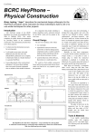
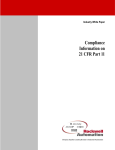
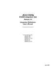
1
SYNC MAX PCI Adapter A high-performance, synchronous communications adapter that supports T1 and E1 speeds Documentation Edition 2 For Revision 2.x or later Editors Becky Mooring Michele Nylander Jennifer Saam Seroj Terian Hardware Scott Graham Al Hodges Kevin Fraze Gabe Fitch Copyright © 1999-2004 by Barr Systems, Inc. All Rights Reserved. Barr Systems, Inc. 4500 NW 27 Avenue Gainesville, FL 32606-7031 Phone: 800-BARR-SYS 800-227-7797 352-491-3100 Fax: 352-491-3141 E-mail: Web site: FTP site: [email protected] www.barrsystems.com ftp.barrsystems.com BARR/RJE and SYNC are trademarks of Barr Systems, Inc. SNA Server is a trademark of Microsoft Corporation. All other trademarks are the sole property of their respective owners. August 20, 2004 ii Preface Preface The SYNC MAX PCI is a high-performance product that offers synchronous communications at T1 (1.536 megabits per second [Mbps]) and E1 (2.048 Mbps) speeds. This manual tells you how to install the SYNC MAX PCI adapter, which is available with the T1-SYNC for SNA Server, BARR/SYNC for Novell Networks, or BARR/RJE software products. See the appropriate software manual for information about loading and configuring the software and running diagnostics. This hardware installation manual includes the following information: Chapter 1 lists computer requirements and package contents. Review this chapter to ensure you have everything you need before you begin the installation. Chapter 2 tells you how to change the communication line interface. Chapter 3 describes how to install the adapter in your computer and connect to a host. Appendix A discusses DCE connections. Barr Technical Support You can contact Barr Systems by e-mail, fax, or phone to work directly with a Support Analyst. Our Frontline and Research support is available five days a week, Monday – Friday, excluding bank holidays. Refer to the Technical Support Web site (www.barrcentral.com) for specific information regarding the hours of operation. Other methods of technical support include on-site visits, remote control service, and FTP server access. You have two easy-to-use support options available 24 hours a day, 7 days a week using the Internet. Knowledgebase – The knowledgebase system (www.barrcentral.com/support/kb) offers a complete database of solutions to known problems. Our knowledgebase is designed to locate solutions based on the symptoms you are experiencing. We search the same knowledge when you call or e-mail us! When we solve your problem, we add it to our knowledgebase. Case Manager – If you’ve looked in our latest documentation and knowledgebase and you still don’t find your answer, you probably need our Technical Support. We’ve opened our case tracking system up to you on Barr Central through Case Manager (www.barrcentral.com/support/cases). With Case Manager you can create a new case, add notes to the case, check its status, and attach diagnostics. Barr Systems is notified of these events so our Support team knows what you need and we keep in contact with you while the issue is being worked on. SYNC MAX PCI Adapter iii When you contact Technical Support, please include the hardware serial number and software version number in your correspondence. You can obtain the adapter serial number from any of the following places: Label on the adapter box Blue sticker on the adapter edge that is visible from the rear of the computer Back of the adapter, where it is handwritten iv Preface Contents Preface ................................................................................................................................... iii 1. Introduction ........................................................................................................................ 1 1.1 Features................................................................................................................... 1 1.2 Computer Requirements.......................................................................................... 2 1.3 Package Contents.................................................................................................... 2 2. Change the Communications Line Interface................................................................... 5 3. Install the SYNC MAX PCI Adapter................................................................................... 7 3.1 Set the BIOS IRQ..................................................................................................... 7 3.2 Insert the Adapter in Your Computer ....................................................................... 7 3.3 Connect to a Modem or Digital Circuit ..................................................................... 8 3.4 Test the Adapter ...................................................................................................... 8 A. DCE Connections .............................................................................................................. 9 A.1 Network Communications ........................................................................................ 9 A.2 Transmission Types...............................................................................................10 Federal Communications Commission Statement ...........................................................11 European Community Statement .......................................................................................13 Glossary ................................................................................................................................15 Index ......................................................................................................................................19 SYNC MAX PCI Adapter v Notes: vi Contents 1. Introduction The SYNC MAX PCI adapter is a 32-bit synchronous adapter card. You can use this adapter with Barr communications software to provide SDLC or X.25 communications at speeds up to T1 (1.536 Mbps) and E1 (2.048 Mbps) on a dedicated line. The SYNC MAX PCI adapter supports the V.24/RS232, X.21, V.35, or RS530 communications line interfaces. 1.1 Features The SYNC MAX PCI adapter includes these features. Supports Data Rates up to 2.048 Mbps The SYNC MAX PCI adapter supports full-duplex operation to achieve high throughput. The SYNC MAX PCI adapter can achieve data rates up to 2.048 Mbps. Barr standard cables use twisted pairs for signal and signal-RTN pairs (for example, CLK and CLK-RTN). Twisted pairs provide the best electrical immunity and results, especially over long distances. Supports Universal Electrical Interfaces The SYNC MAX PCI adapter includes onboard support for the popular electrical interface specifications, including V.35, X.21, V.24/RS232, or RS530. The adapter comes with the cable you specify. You can change the adapter from one interface to another by switching to the correct cable, which you can order from Barr Systems. Barr standard cables use twisted pairs for signal and signal-RTN pairs (for example, CLK and CLK-RTN). Twisted pairs provide the best electrical immunity and results, especially over long distances. SYNC MAX PCI Adapter 1 Supports Modem or SME Connection You can attach the SYNC MAX PCI adapter to a modem, to another computer, or directly to a front-end processor (FEP). To connect to a computer or FEP, you must use an optional synchronous modem eliminator (SME) cable. An SME cable eliminates the need for modems or a modem eliminator box. If you place your computer within 30 meters (100 feet) of the mainframe, you can use an SME cable to directly connect the computer to the FEP or mainframe communications controller. The adapter produces the modem clock signal, and the SME cable can accept the clock signal from the adapter. The FEP is still configured for a modem connection. You can purchase SME cables from Barr Systems. 1.2 Computer Requirements You can install SYNC MAX PCI hardware on a computer that meets the following requirements: PCI bus One 32-bit slot for the SYNC MAX PCI adapter 1.3 Package Contents The SYNC MAX PCI hardware package includes this adapter: SYNC MAX PCI adapter 2 1. Introduction The package also includes one of the following cables, depending on which interface you specified: Cable for V.35 standard with test plug Cable for V.24/RS232 standard with test plug Cable for X.21 standard with test plug Cable for RS530 standard with test plug Note: The SYNC MAX PCI adapter package includes the cable or cables you specify when you order the product. If you need to change communication interfaces, you can order the other cables separately from Barr Systems. See your Barr software manual for software package contents. SYNC MAX PCI Adapter 3 Notes: 4 1. Introduction 2. Change the Communications Line Interface The SYNC MAX PCI adapter supports the popular electrical interface specifications listed below. You can change the adapter from one interface to another by simply connecting a different cable. V.24/RS232 is the most common low-speed modem interface. Although technically defined for cable lengths up to 15 meters (50 feet) and speeds up to 19.2 Kbps, you can sometimes use higher data rates with excellent results. V.35 is the most common interface for high-speed modems and channel service unit/data service unit (CSU/DSU) interfaces. Users frequently use it for data rates of 56 Kbps and higher. X.21 uses pairs of wires for each signal to increase noise immunity and enhance speed and distance capabilities. This modem interface is popular in Europe. RS530 uses pairs of wires for each signal. It defines a 25-pin connector, but it is otherwise similar to the older RS449, RS422, and RS423 standards that used a 37-pin connector. You can use RS530 with high data rates and longer cable lengths. SYNC MAX PCI Adapter 5 Notes: 6 2. Change the Communications Line Interface 3. Install the SYNC MAX PCI Adapter You can install the SYNC MAX PCI adapter in an open PCI slot in your computer. Follow these steps to install the adapter. 1. Verify that an IRQ setting is available for PCI adapters. 2. Install the adapter in your computer. 3. Connect the adapter to a modem or digital circuit with the cable. 4. Run the adapter diagnostics. 3.1 Set the BIOS IRQ PCI technology means you do not have to set any adapter switches or jumpers, but it does require some computer setup. Although your computer’s BIOS program can automatically set up PCI and ISA adapters, it might encounter interrupt request (IRQ) level conflicts with non-PCI adapters. Note: DMA and address conflicts are unlikely with PCI adapters. PCI adapters typically do not use a DMA setting and their address range differs from non-PCI adapters. To prevent conflicts, you need to tell BIOS which IRQ settings your non-PCI adapters use. You also need to make sure that at least one IRQ is available for PCI adapters. Before you install the SYNC MAX PCI adapter, use your computer setup utility to check the BIOS IRQ settings. See your computer user’s manual for instructions. Note: The device drivers that accompany some PCI adapters might not allow interrupt sharing. If a conflict exists, the software will not function correctly when you try to start or operate it. If you detect a conflict, contact the vendor of the other PCI adapter. 3.2 Insert the Adapter in Your Computer Your computer owner’s manual describes how to install the adapter card. SYNC MAX PCI Adapter 7 Caution: Disconnect your computer and all attached devices from power sources before you install the SYNC MAX PCI adapter. 3.3 Connect to a Modem or Digital Circuit After you install the adapter in your computer, you can connect it to a modem or to the line interface of a digital leased circuit with the appropriate cable. You can also directly connect to another computer or to a host FEP with an SME cable. This section describes how to connect the SYNC MAX PCI adapter to the FEP or mainframe communications controller with the appropriate Barr SYNC SME cable. Appendix A discusses Data Circuit Terminating Equipment (DCE) connections. The end of the cable with the D37 connector plugs into the computer adapter. The other end of the cable connects to a cable extending from the FEP’s line interface coupler (LIC). LIC cables: You can choose from two types of LIC cables at the mainframe: one type connects to a Data Terminal Equipment (DTE) device, and the other connects to a DCE (modem). Because the adapter produces the modem clock signal, you must use the LIC cable designed to connect to a DCE. You must also configure the FEP for a modem connection. Follow these steps to connect the adapter directly to the FEP: 1. Plug the end of the SYNC SME cable with the D37 connector into the SYNC MAX PCI adapter. 2. Plug the other end of the SYNC SME cable into the LIC cable that extends from the FEP. Set the communications speed in the Barr software (see the appropriate Barr software manual). Check with your host programmer to verify supported speeds at the FEP/scanner. 3.4 Test the Adapter After you install the adapter, install the Barr software and run the adapter diagnostics as described in your Barr software manual. Adapter diagnostics verify that you have correctly installed the adapter and that it functions properly. 8 3. Install the SYNC MAX PCI Adapter A. DCE Connections The Barr hardware and software product emulates a DTE device. The Barr-provided cable works on most DTE-DCE connections. A.1 Network Communications Barr products allow you to access analog, digital, and public networks. Typically in the analog and digital environments, modems and DSUs emulate DCE devices. This section briefly describes how you can implement Barr products in these networking environments. Analog Communications With analog communications, the computer sends signals in digital form to a modem. Then telephone lines transfer data between the modem and the host computer. The word modem is derived from the terms modulate and demodulate. When the computer transmits, the modem converts (modulates) digital signals to the analog signals the telephone system uses. When the computer receives, the modem restores (demodulates) the signal to digital form. The modems at each end of the transmission line (the host’s modem and the remote computer’s modem) operate at the same speed (bits per second [bps]) and must keep in step with one another. Communications are timed synchronously or asynchronously. Barr products support synchronous communications and require synchronous modems. Digital Communications Digital networks around the world transmit video, voice, image, and bulk data with extremely high accuracy. CSU/DSUs, multiplexers, and frame relay devices (FRADs) are common DCE interfaces to these networks. Digital signals are transmitted in a bipolar format at high speeds and can be multiplexed together and routed to the appropriate devices. Clocking can be supplied by the service provider or the DCE equipment. Barr synchronous adapters connect to these networks at up to E1 speeds. The RS232 interface has been used at speeds up to 56 Kbps, but the V.35 interface is usually recommended for 56 Kbps or above. Your DCE device determines the required interface. Public or Multipurpose Networks Public or multipurpose networks such as X.25 or ISDN usually integrate their own communications equipment as a means of access. Although the Barr X.25 software eliminates this need, X.25 access can be provided with a packet assembler/dissassembler (PAD). ISDN access is handled by ISUs or terminal adapters. The X.21 interface is commonly used in these environments, most notably in Europe. SYNC MAX PCI Adapter 9 A.2 Transmission Types Modems on dial-up telephone lines communicate at various speeds and code bits of data with various modulation techniques. Modem standards define these modulation techniques. Modems you use on the dedicated line must conform to the host computer center’s standard. If you do not have a modem, ask the host consultant about modem types the host supports. Synchronous Transmission Synchronous transmission incorporates a clocking mechanism induced by the signal carrier that does not need start bits. The software sends successive characters without intervening start and stop bits. The receiver stays synchronized with the sender by constantly evaluating the clock periods in the received signal. The transmission message consists of many characters. Synchronous transmission eliminates the inefficiency of stopping and starting between characters. Asynchronous Transmission Asynchronous transmission communicates with a single character preceded by a start bit and followed by one or two stop bits. Essentially, the transmission message contains one character with no restriction on the length of time between messages. Low-speed terminals use asynchronous transmission (also called start-stop transmission) to communicate with interactive systems. In dial-up environments with Hayes-compatible modems, the modems should initially be set to asynchronous mode. The Barr software configures the modem using AT commands and dynamically sets up the modem for synchronous transmission. 10 A. DCE Connections Federal Communications Commission Statement This equipment has been tested and found to comply with the limits for a Class A digital device pursuant to Part 15 of the FCC Rules. These limits are designed to provide reasonable protection against harmful interference when the equipment is operated in a commercial environment. This equipment generates, uses, and can radiate radio frequency energy and, if not installed and used in accordance with the instruction manual, might cause harmful interference to radio communications. Operation of this equipment in a residential area is likely to cause harmful interference. If this happens, users will be required to correct the interference at their own expense. Note: A shielded and grounded cable is required. SYNC MAX PCI Adapter 11 Notes: 12 Federal Communications Commission Statement European Community Statement The following is a declaration of conformity for the European community. SYNC MAX PCI Adapter 13 Notes: 14 European Community Statement Glossary adapter Add-on piece of equipment you can plug into a computer to allow the computer to connect to another device. analog Refers to data represented by a physical variable that varies in a continuous rather than discrete manner and is usually represented by an electrical signal. asynchronous A communications technique in which each character is transmitted as a discrete unit. The character transmitted is preceded by a start bit and followed by one or more stop bits. As each character is bracketed by start and stop bits, varying amounts of time can elapse between characters. Contrasts with synchronous communication. Also called start-stop communications. block A contiguous vector of bits read or written as a unit. A block can include one or more records. Blocks are usually a fixed size. bps Abbreviation for bits per second. A unit of measure for the rate that information is transferred. SYNC MAX PCI Adapter byte A string consisting of a number of bits treated as a unit and representing a character. Usually a string of eight adjacent binary digits that represent one EBCDIC character. connector An attachment at the end of a wire or set of wires that facilitates their connection to a device. Any attachment that facilitates connection to a device. communication controller A communication control unit that manages line control and data transfer through a network. Operations are controlled by one or more programs stored and executed in the unit. Examples are the IBM 3705, 3725, and 3745 Communication Controllers. communications line Any physical medium, such as a wire or microwave beam, that is used to transmit data. CSU/DSU Acronym for Channel Service Unit/Data Service Unit. CSU is an AT&T unit that is part of the AT&T nonswitched digital data system. DSU is a device that provides a digital data service interface directly to the data terminal equipment. The DSU provides loop equalization, remote and local testing capabilities, and a standard EIA/CCITT interface. 15 dedicated line Same as nonswitched line. A connection between systems or devices that does not have to be made by dialing. device address A number that uniquely identifies a device. diagnostics A program to detect and isolate errors in programs and faults in equipment. DIP switch A two-position switch on a circuit board that is preset to control certain functions; the user can change the position of a DIP switch to satisfy special requirements. DMA Acronym for Direct Memory Access. A technique for moving data directly between main storage and peripheral equipment without requiring processing of the data by the processing unit. EISA Acronym for Extended Industry Standard Architecture. A 32-bit extension of the 8- and 16-bit internal bus structure developed by IBM. Developed by Compaq Computer Corp. and other computer manufacturers. 16 front-end processor A processor that relieves the host computer of certain processing tasks, such as line control, message handling, code conversion, and error control. Examples include the 3725 and 3745. full-duplex Describes a communication link that allows simultaneous transmission of data in both directions (in contrast to half-duplex). host computer A computer that controls the communications network and has databases and large computing and memory capacity. Other computers can connect to the host to share its resources. interface The connection between any two components in a system. The term is used for the connection between both software and hardware components. IRQ Acronym for Interrupt Request. A request for processing on a particular priority level. ISA Acronym for Industry Standard Architecture, a standard for the computer’s expansion bus (where you plug in add-on adapters). The IBM AT bus became a 16-bit ISA. Glossary K Abbreviation for kilobyte. Two to the tenth power or 1,024 in decimal notation. Kbps Abbreviation for kilobits per second. kilobyte (KB) A unit that is 1,024 bytes in decimal notation or 10000000000 in binary notation. Each byte is eight bits long. In computer literature, the kilo- prefix means “times 1,024.” LAN Acronym for Local Area Network. A high-speed communications network within a limited geographic area. Typically, several computers are linked together within a single building or campus. (In contrast, a wide-area network may span hundreds or thousands of miles.) LIC Acronym for Line Interface Coupler. line trace A recording of the frames sent and received on a communication line useful for diagnosing communications problems. loopback A testing procedure in which transmitted data are returned as received data. SYNC MAX PCI Adapter mainframe Term used for a large central computer that offers a full set of computing services. The term originated in the days when the central processor, memory, and input/output channels were located in one central housing called the mainframe. Synonymous with host computer. MB Abbreviation for megabyte. One million bytes (more accurately, 1,048,576 bytes). Mbps Abbreviation for megabits per second. megabit One million bits. modem Short for modulator/demodulator. A device designed to interface between a digital communication link and an analog communication link. Usually the digital communication link is a computer or terminal. The analog communication link is usually a telephone line. To modulate is to convert a digital signal from the computer into an analog signal capable of being transmitted by the telephone system. Demodulate is the opposite of modulate. 17 PCI Acronym for Peripheral Component Interconnect. Standard for a highperformance, 32-bit or 64-bit computer local bus with multiplexed address and data lines. Enables fully automatic configuration of add-on adapters. pin One of the conducting contacts of an electrical connector. RS232 Refers to EIA Standard RS232C for connecting data communication equipment to data terminal equipment, including the connection of terminals and computers to modems. Many computer peripheral devices also use this interface for connection to the computers. See serial interface port. synchronous adapter Communications adapter that allows connection to a synchronous modem. synchronous communication Mode of communication in which blocks of characters are sent as a unit without start and stop bits for each character. Unlike asynchronous communication, the timing for data is obtained from the carrier signal and is not a function of time-from-the-start bit. twisted pair A transmission medium that consists of two insulated electrical conductors twisted together to reduce noise. 18 Glossary Index A K Adapter serial number · iv Adapters · 2 Knowledgbase · iii B L BIOS · 7 LIC cables · 8 Line interface coupler (LIC) · 8 C M Cables · 1 Case Manager · iii Communications line interface · 5 Computer requirements · 2 Mainframe · 2 R RS530 cable · 5 D D37 connector · 8 Data rates · 1 DCE connections · 8 Diagnostics · 8 DMA · 7 DTE device · 8, 9 E S Signal · 1 Signal-RTN · 1 SME cable · 2, 8 SYNC MAX PCI adapter · 2 T E1 speed · iii, 1, 9 Electrical interfaces · 1 T1 speed · iii, 1 Technical Support · iii Twisted pairs · 1 F V Front-end processor (FEP) · 2, 8 V.24/RS232 cable · 3, 5 V.35 cable · 3, 5 I Interrupt sharing · 7 IRQ conflicts · 7 SYNC MAX PCI Adapter X X.21 cable · 3, 5 19 Notes: 20 Index