1
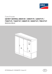
Central Inverter
SUNNY CENTRAL and Accessories
Maintenance Manual
SCWAR-WEN094020 | 98-4005820 | Version 2.0
EN
SMA Solar Technology AG
Table of Contents
Table of Contents
1
1.1
1.2
1.3
1.4
1.5
Notes on this Manual. . . . . . . . . . . . . . . . . . . . . . . . . . . . . .
Scope of Validity. . . . . . . . . . . . . . . . . . . . . . . . . . . . . . . . . . . . .
Target Group . . . . . . . . . . . . . . . . . . . . . . . . . . . . . . . . . . . . . . .
Documentation . . . . . . . . . . . . . . . . . . . . . . . . . . . . . . . . . . . . . .
Spare parts . . . . . . . . . . . . . . . . . . . . . . . . . . . . . . . . . . . . . . . . .
Symbols Used . . . . . . . . . . . . . . . . . . . . . . . . . . . . . . . . . . . . . . .
6
6
6
6
6
7
2
2.1
Safety . . . . . . . . . . . . . . . . . . . . . . . . . . . . . . . . . . . . . . . . . . 8
Safety Instructions . . . . . . . . . . . . . . . . . . . . . . . . . . . . . . . . . . . . 8
2.1.1
Electrical safety . . . . . . . . . . . . . . . . . . . . . . . . . . . . . . . . . . . . . . . . . . . . . . . . .8
2.1.2
Personnel. . . . . . . . . . . . . . . . . . . . . . . . . . . . . . . . . . . . . . . . . . . . . . . . . . . . . .8
2.1.3
Torque . . . . . . . . . . . . . . . . . . . . . . . . . . . . . . . . . . . . . . . . . . . . . . . . . . . . . . . .8
3
3.1
3.2
3.3
3.4
Maintaining the Sunny Central . . . . . . . . . . . . . . . . . . . . . . 9
Identifying the Sunny Central . . . . . . . . . . . . . . . . . . . . . . . . . . . 9
Reading out Long-term Data and Error Memory. . . . . . . . . . . . 10
Cleaning the Power Electronics. . . . . . . . . . . . . . . . . . . . . . . . . 10
Maintaining the air inlet filter . . . . . . . . . . . . . . . . . . . . . . . . . . 11
3.4.1
General Activities . . . . . . . . . . . . . . . . . . . . . . . . . . . . . . . . . . . . . . . . . . . . . 11
3.4.2
Sunny Central 100LV / SC 150 / SC 125LV / SC 200 / 200HE . . . . . . . 12
3.4.3
Sunny Central 250 / 250HE . . . . . . . . . . . . . . . . . . . . . . . . . . . . . . . . . . . . 13
3.4.4
Sunny Central 350 / SC 350HE . . . . . . . . . . . . . . . . . . . . . . . . . . . . . . . . . 13
3.4.5
Sunny Central 500HE / 560HE / 400HE-11 / 500HE-11 / 630HE-11 . . 14
3.5
Cleaning the insect guard. . . . . . . . . . . . . . . . . . . . . . . . . . . . . 14
3.5.1
Sunny Central 100 outdoor (older model) . . . . . . . . . . . . . . . . . . . . . . . . . . 15
3.5.2
Sunny Central 100 indoor /outdoor (new model) . . . . . . . . . . . . . . . . . . . . 16
3.5.3
Removing the roof . . . . . . . . . . . . . . . . . . . . . . . . . . . . . . . . . . . . . . . . . . . . . 17
3.5.4
Removing the plinth panels . . . . . . . . . . . . . . . . . . . . . . . . . . . . . . . . . . . . . . 19
3.5.5
Removing the exhaust air filter in the base . . . . . . . . . . . . . . . . . . . . . . . . . . 19
Maintenance Manual
SCWAR-WEN094020
3
Table of Contents
3.6
3.7
3.8
3.9
3.10
3.11
SMA Solar Technology AG
Sunny Central 100LV / SC 125LV / SC 150 /SC 200 /
200HE . . . . . . . . . . . . . . . . . . . . . . . . . . . . . . . . . . . . . . . . . . . 20
Sunny Central 250 / 250HE . . . . . . . . . . . . . . . . . . . . . . . . . . 21
Sunny Central 350 / SC 350HE . . . . . . . . . . . . . . . . . . . . . . . 22
Sunny Central 500HE / 560HE / 400HE-11 / 500HE-11 /
630HE-11. . . . . . . . . . . . . . . . . . . . . . . . . . . . . . . . . . . . . . . . . 23
Sunny Central 400 / 500 / 700 / 1000 / 1120MV. . . . . . . 25
Maintaining the heat exchanger. . . . . . . . . . . . . . . . . . . . . . . . 27
3.11.1
Disassembling the heat exchanger for
Sunny Central 200 / 250 . . . . . . . . . . . . . . . . . . . . . . . . . . . . . . . . . . . . . . 27
3.11.2
Disassembling the heat exchanger of
Sunny Central 400HE-11 / 500HE-11 /630HE-11 . . . . . . . . . . . . . . . . . . 31
4
4.1
4.2
4.3
4.4
Covers and lockings. . . . . . . . . . . . . . . . . . . . . . . . . . . . . . 35
Checking the emergency stop. . . . . . . . . . . . . . . . . . . . . . . . . . 35
Checking the door contact switch. . . . . . . . . . . . . . . . . . . . . . . 36
Checking the seals . . . . . . . . . . . . . . . . . . . . . . . . . . . . . . . . . . 37
Checking of lockings and hinges . . . . . . . . . . . . . . . . . . . . . . . 37
5
5.1
5.2
5.3
5.4
5.5
5.6
5.7
Maintaining the inside of the switch cabinet . . . . . . . . . . 38
Checking the inside of the switch cabinet for contamination . . 38
Cleaning the power unit of the heat sink . . . . . . . . . . . . . . . . . 39
Cleaning the EVR resistor . . . . . . . . . . . . . . . . . . . . . . . . . . . . . 40
Checking the power cable connections . . . . . . . . . . . . . . . . . . 41
Checking the safety notices . . . . . . . . . . . . . . . . . . . . . . . . . . . 41
Checking the Fans. . . . . . . . . . . . . . . . . . . . . . . . . . . . . . . . . . . 42
Checking the heating and the hygrostat . . . . . . . . . . . . . . . . . . 43
6
6.1
6.2
Checking protective devices . . . . . . . . . . . . . . . . . . . . . . . 45
Checking the residual current circuit breaker in the SC 100 . . 45
Checking the circuit breaker . . . . . . . . . . . . . . . . . . . . . . . . . . . 46
4
SCWAR-WEN094020
Maintenance Manual
SMA Solar Technology AG
Table of Contents
6.3
Checking the DC main switch . . . . . . . . . . . . . . . . . . . . . . . . . . 47
6.3.1
Circuit breaker and switch-disconnector . . . . . . . . . . . . . . . . . . . . . . . . . . . . 47
6.4
6.5
Checking the fuses and disconnectors . . . . . . . . . . . . . . . . . . . 48
Checking the overvoltage arrester . . . . . . . . . . . . . . . . . . . . . . 49
6.5.1
Checking the Dehn Guard . . . . . . . . . . . . . . . . . . . . . . . . . . . . . . . . . . . . . . 49
6.5.2
Checking the Blitzductor . . . . . . . . . . . . . . . . . . . . . . . . . . . . . . . . . . . . . . . . 50
6.6
Maintaining the GFDI . . . . . . . . . . . . . . . . . . . . . . . . . . . . . . . . 50
6.6.1
Replacing the GFDI. . . . . . . . . . . . . . . . . . . . . . . . . . . . . . . . . . . . . . . . . . . . 51
6.7
Maintaining the soft grounding. . . . . . . . . . . . . . . . . . . . . . . . . 51
7
7.1
7.2
Additional notes for Sunny Central 100 . . . . . . . . . . . . . 52
Checking the transformer and sinusoidal filter . . . . . . . . . . . . . 52
Checking the cable feed of the SC 100outdoor . . . . . . . . . . . 53
8
8.1
Additional notes for MV stations . . . . . . . . . . . . . . . . . . . 54
Checking the cable feed of the concrete substations . . . . . . . . 54
9
Maintaining the Sunny String-Monitor . . . . . . . . . . . . . . . 55
10
Maintaining the Sunny String-Monitor-Cabinet . . . . . . . . 58
11
Maintaining the Sunny String-Monitor SSM24-11 . . . . . 61
12
Maintaining the Sunny Main Box . . . . . . . . . . . . . . . . . . . 65
13
Contact . . . . . . . . . . . . . . . . . . . . . . . . . . . . . . . . . . . . . . . . 66
Maintenance Manual
SCWAR-WEN094020
5
Notes on this Manual
SMA Solar Technology AG
1 Notes on this Manual
1.1 Scope of Validity
This document describes how to maintain the Sunny Central indoor and outdoor central inverters. It is
valid for all switch cabinet versions, the MV stations as well as their accessories such as
Sunny String-Monitor, Sunny String-Monitor-Cabinet and Sunny Main Box.
1.2 Target Group
This document is for installers and operators of a Sunny Central. It includes a description of the
maintenance of the Sunny Central, the intervals and the maintenance work. The appropriate
maintenance protocol describes the replacement intervals of the components that need to be
replaced.
1.3 Documentation
The documents listed below are included in the scope of delivery for your Sunny Central. The
following information is contained in these documents.
• Installation guide:
• User manual:
• Circuit diagrams:
• Technical data sheets:
• Commissioning report
• Maintenance manual
• Maintenance protocol
Setup and installation of the Sunny Central
How to operate the Sunny Central and Sunny
Central Control
Sunny Central circuit diagrams including torques
and the equipment list with all article numbers.
Technical data pertaining to the Sunny Central
Check list for commissioning
Maintenance of the Sunny Central and its
accessories
Check list for maintenance
1.4 Spare parts
You can find the article number of the individual spare parts in the equipment list in the circuit diagram.
You can obtain the article numbers from SMA Solar Technology.
6
SCWAR-WEN094020
Maintenance Manual
SMA Solar Technology AG
Notes on this Manual
1.5 Symbols Used
The following four types of safety notices and general information are used in this document:
DANGER!
DANGER indicates a hazardous situation which, if not avoided, will result in death or
serious injury.
WARNING!
WARNING indicates a hazardous situation which, if not avoided, could result in death or
serious injury.
CAUTION!
CAUTION indicates a hazardous situation which, if not avoided, could result in minor or
moderate injury.
NOTICE!
NOTICE indicates a situation that can result in damage to property if not avoided.
Information
Information provides tips that are valuable for the optimal installation and operation of
your product.
Maintenance Manual
SCWAR-WEN094020
7
Safety
SMA Solar Technology AG
2 Safety
2.1 Safety Instructions
2.1.1 Electrical safety
High voltages are present in the device.
All work on the Sunny Central must be carried out exactly as described in the maintenance manual
and all safety precautions must be observed. Follow all safety precautions of the Sunny Central's
installation guide. Do not touch the live components of the Sunny Central or the medium-voltage grid.
Observe all safety regulations regarding the medium-voltage grid.
Damage to the Sunny Central, e.g. defective cables or damaged enclosure, can lead to death by
electric shock or fire!
The Sunny Central may only be used when it is technically faultless and safe to operate. Operate the
Sunny Central only if there are no visible damages. Regularly check the Sunny Central for visible
damage. Ensure that all external safety features are accessible at all times, and that they are regularly
tested for correct functionality!
Electrostatic discharge can damage the Sunny Central.
When working on the Sunny Central and handling components, observe all ESD safety regulations.
Discharge electrostatic charge by touching the grounded Sunny Central enclosure. before handling
electronic components!
2.1.2 Personnel
Only qualified technical personnel may perform work on the MV station. Qualified means that the
personnel must possess training relevant to the activity performed and must be familiar with the
content of this manual.
2.1.3 Torque
Always observe the torques of the individual components. You will find the torques in the circuit
diagram of the respective device. If you cannot find the corresponding torques in the device's
documentation, contact the Sunny Central Service.
8
SCWAR-WEN094020
Maintenance Manual
SMA Solar Technology AG
Maintaining the Sunny Central
3 Maintaining the Sunny Central
The Sunny Central, the string monitoring units and the communication units must be maintained at
regular intervals. Maintenance includes the following activities:
• Inspection of wearing parts, and replacement if necessary
• Functional test of components
• Inspection of contact joints
• Cleaning of cabinet interior, if necessary
A maintenance protocol is enclosed with every Sunny Central. The maintenance protocol describes
the maintenance work to be carried out and the maintenance interval recommended by SMA Solar
Technology.
Maintenance intervals
The maintenance interval depends on the location and the ambient conditions. A device
installed in an environment with very dusty ambient air requires more frequent maintenance
than recommended. The maintenance interval is to be adapted accordingly.
3.1 Identifying the Sunny Central
You can identify the Sunny Central using the type label. The type label is located on the inside of the
Sunny Central’s door.
In addition, the serisl number (A) is located on the front
side of the device.
A
Maintenance Manual
SCWAR-WEN094020
9
Maintaining the Sunny Central
SMA Solar Technology AG
3.2 Reading out Long-term Data and Error Memory
In order to ensure smooth plant operation, all plant components must be optimally matched to one
another. Deviations from the optimum operation can result in yield losses and thus in a reduction of
the plant's profitability.
Even though there are - depending on the plant communication - several features which issue a
warning to the plant operator in case of string failure or malfunctions of the inverter, a regular check
of the plant operation is necessary to recognize possible failures which have no alarm function.
Furthermore, plant operation might be improved by analyzing the plant data.
Depending on the plant size, the error memory of the central inverter as well as the long-term data of
the data logger must be analyzed at least once a month. Proceed as described in the user manual.
3.3 Cleaning the Power Electronics
DANGER!
Death resulting from electric shock and burning upon touching the mediumvoltage grid's live components.
• Only work on the device when it is switched off and voltage-free.
The power electronics of the Sunny Central inverters is considerably well-protected and thus requires
almost no maintenance work. Only carry out a visual inspection and clean the circuit boards with a
soft brush or a vacuum cleaner with a soft top part if there are dust deposits. The cleaning equipment
must be anti-static and ESD-compliant. Do not use any hard or coarse brushes. Using pressurized air
is prohibited.
10
SCWAR-WEN094020
Maintenance Manual
SMA Solar Technology AG
Maintaining the Sunny Central
3.4 Maintaining the air inlet filter
3.4.1 General Activities
DANGER!
Death resulting from electric shock and burning upon touching the mediumvoltage grid's live components.
• Only work on the device when it is switched off and voltage-free.
Cleaning or replacing the filter pads in the air inlet filters
This section describes how to disassemble and clean the ventilation grids as well as how to replace
the corresponding air filter pads. Depending on the switch cabinet type and model, ventilation grids
which have filter pads must be maintained. The filter pads must be cleaned and replaced, if the degree
of pollution is too high. The Sunny Central 100 only has ventilation grids without air filter pads.
Disassembling and installing the ventilation grids with the appropriate filter pads
1. Slightly lift the top part of the ventilation grid by using
a screwdriver and pull the grid together with the top
part forward. The frame of the ventilation grids is
securely attached to the switch cabinet's door and
cannot be removed.
2. Remove the filter pads. The filter pad is in a cutout in
the top part of the ventilation grid.
3. If the filter pad needs to be replaced, you can order it
from SMA: Article number 65-102011.
4. Insert the filter pad. During mounting, the white side
must point outwards and the bluish side to the inside
of the switch cabinet.
Smaller filter pads
There is no separate article number for the small filter pads which are installed in the older
version of the Sunny Central 500; they have to be cut out from the large filter pads.
Maintenance Manual
SCWAR-WEN094020
11
Maintaining the Sunny Central
SMA Solar Technology AG
Cleaning the filter pads
• Clean with water (up to approx. 40 °C; you can also additionally use commercially available
mild detergent).
• Tap or vacuum the filter material, or carefully use pressurized air to remove the contamination.
• For dust containing grease, you should rinse with warm water and additionally use degreaser.
The air filter pad may not be cleaned with strong water jet or wrung out.
• As soon as the air filter pads are cleaned and dried, put them back into the frame.
Cleaning the ventilation grids
• The grids can be cleaned using a paintbrush, vacuum, or applying pressurized air.
Position of the ventilation grids
With the help of some example cabinets, the following section shows the exact position
and size of the individual ventilation grids.
3.4.2 Sunny Central 100LV / SC 150 / SC 125LV / SC 200 / 200HE
The switch cabinets of type SC 100LV, SC 150,
SC 125 LV and SC 200 are mostly identical in
construction and equipped with four large air inlet filters
(A).
12
SCWAR-WEN094020
Maintenance Manual
SMA Solar Technology AG
Maintaining the Sunny Central
3.4.3 Sunny Central 250 / 250HE
The switch cabinet of the SC 250 is equipped with six large (A) air inlet filters. The switch cabinets of
the new series have four further air inlet filters in the AC cabinet.
3.4.4 Sunny Central 350 / SC 350HE
The switch cabinet of the SC 350 is equipped with eight
large (A) air inlet filters.
Maintenance Manual
SCWAR-WEN094020
13
Maintaining the Sunny Central
SMA Solar Technology AG
3.4.5 Sunny Central 500HE / 560HE / 400HE-11 / 500HE-11 /
630HE-11
Depending on the design, the switch cabinet of the SC 500HE is equipped with two small air inlet
filters (A) and six large air inlet filters (B) or only eight large air inlet filters (B). Only in this model, the
switch cabinet of the SC 560HE is equipped with eight large air inlet filters.
3.5 Cleaning the insect guard
Cleaning the insect guards at the air inlets and outlets
This section describes how to clean the insect guards at the air inlets and outlets.
Exchanging the protective grids
Exchanging the protective grids is only necessary in case of damage.
DANGER!
Death resulting from electric shock and burning upon touching the mediumvoltage grid's live components.
• Only work on the device when it is switched off and voltage-free.
Depending on the switch cabinet type and model, the insect guards must be cleaned in the roof and
plinth area, in the doors of the inverter cabinets and back sides of the doors. The air for cooling the
power units is drawn through and blown out through these insect guards.
The guards can be cleaned using a paintbrush, or handheld brush or by vacuuming, or applying
pressurized air.
Cleaning fine guards using pressurized air is prohibited. They are designed thinner and are used for
finger protection. Such protective grids are installed on the rear of the switch cabinets.
14
SCWAR-WEN094020
Maintenance Manual
SMA Solar Technology AG
Maintaining the Sunny Central
Position of the protective grids
The following examples illustrate the exact position and size of the individual protective
grids.
3.5.1 Sunny Central 100 outdoor (older model)
The switch cabinet of the SC 100 is equipped with a protective grid in the plinth area. The cooling air
is drawn through the filter in the plinth and blown out through the guard plate on the back panel of
the inverter.
Front view
Ventilation
Rear view
Maintenance Manual
SCWAR-WEN094020
15
Maintaining the Sunny Central
SMA Solar Technology AG
3.5.2 Sunny Central 100 indoor /outdoor (new model)
Both cabinets have large-meshed protective grids (A) in the roof and one in the plinth area.
View of the SC 100 ventilation
The air is drawn sucked-in trough the roof. In the
outdoor version, the air is emitted through the
plinth, in the indoor version through the roof. The
actual airflow is protected by the plinth panel as
well as by the roof and has a further air filter, in this
case a fine-meshed air filter. The indoor version
has no filter in the exhaust air area; it is not
included in the delivery. In this case also the base
is sealed with a plate.
Protective grid
Cleaning the filter of the supply air requires a prior
disassembly of the roof.
Cleaning the filter of the exhaust air requires a
prior disassembly of the plinth panel.
Protective grid
16
SCWAR-WEN094020
Maintenance Manual
SMA Solar Technology AG
Maintaining the Sunny Central
3.5.3 Removing the roof
The Sunny Central 100 indoor usually has an air duct through which the exhaust air is emitted to the
outside. The air duct must be disassembled in order to remove the roof.
Depending on the product version, the Sunny Central 100 is produced with different roofs. The
following describes how to disassemble the roof of both production versions.
Disassembling version 1
1. Loosen the screws at the left side in the roof of the
Sunny Central.
SUNN
Y CE
NTRA
0
L 10
A
A
2. Loosen the screws at the right side in the roof of the
Sunny Central.
3. Lift the roof (1).
4. Remove the Start / Stop switch (2).
☑ The roof is removed.
Maintenance Manual
SCWAR-WEN094020
17
Maintaining the Sunny Central
SMA Solar Technology AG
Disassembling version 2
1. Remove the Start / Stop switch.
2. Loosen the screws at the front filter in the roof of the
Sunny Central.
3. Loosen the screws at the back filter of the Sunny
Central.
4. Pull the front filter forward and remove it.
5. Pull the rear filter forward and remove it. Put the filters
aside.
NY
SUN
0
L 10
TRA
CEN
6. Remove the screws (A) which hold the roof at the
Sunny Central. The screws are in the place where the
front filter was attached before.
☑ The roof can now be tilted backwards (1) to clean
the filter in the roof of the switch cabinet.
➤ If there is not enough space to tilt the roof backwards,
remove it. To do so, loosen the cable gland (2) of the
switch.
7. Unhook the roof and remove it by pulling it upwards.
☑ The roof is removed.
18
SCWAR-WEN094020
Maintenance Manual
SMA Solar Technology AG
Maintaining the Sunny Central
3.5.4 Removing the plinth panels
Depending on the production version, the plinth panel of
the Sunny Central 100 consists of one unit or two units.
Identical plinth panels are installed in both production
versions.
1. Loosen the screws on the edges of the plinth panel.
SM A
2. Remove the plinth panel by pulling it forward.
SMA
☑ The plinth panel is removed.
3.5.5 Removing the exhaust air filter in the base
1. Loosen the thumb nut at the filter in the base of the
switch cabinet.
2. Remove the filter.
☑ The filter can now be cleaned.
Maintenance Manual
SCWAR-WEN094020
19
Maintaining the Sunny Central
SMA Solar Technology AG
3.6 Sunny Central 100LV / SC 125LV / SC 150 /SC 200 / 200HE
The switch cabinets of type SC 100LV, SC 150, SC 125LV and SC 200 are mostly identical in
construction and equipped one protective grid (A) in the front. The exhaust air can either be
discharged to the top or the back. The inverter is therefore equipped with a protective grid (A) in the
roof or on the back side.
20
SCWAR-WEN094020
Maintenance Manual
SMA Solar Technology AG
Maintaining the Sunny Central
3.7 Sunny Central 250 / 250HE
The switch cabinet of the SC 250 / 250HE has two protective grids (A) in the front of the inverter
cabinet. The exhaust air can either be discharged to the top or the back. Consequently, this device
has either a grid (A) on the back side or in the roof.
Maintenance Manual
SCWAR-WEN094020
21
Maintaining the Sunny Central
SMA Solar Technology AG
3.8 Sunny Central 350 / SC 350HE
The switch cabinet of the SC 350 has two protective grids (A) each in the front and on the back of
the inverter cabinet.
22
SCWAR-WEN094020
Maintenance Manual
SMA Solar Technology AG
Maintaining the Sunny Central
3.9 Sunny Central 500HE / 560HE / 400HE-11 / 500HE-11 /
630HE-11
Depending on the model, the switch cabinet of the SC 500HE has three protective grids (A) or one
protective grid (A) of another type in the front of the inverter cabinet. The SC 500HE model with three
protective grids in the front also has three protective grids at the real panel. The switch cabinet of the
SC 560HE is delivered with only one protective grid (A).
The switch cabinets of the series "11" have the same protective grids as the Sunny Central 560HE.
The devices mostly require no maintenance work. Due to the airflow of the power units positioned
above one another, dirt of the bottom power unit may remain in the switch cabinet. Vacuum the
chamber behind the bottom power unit for cleaning through the ventilation shaft.
Maintenance Manual
SCWAR-WEN094020
23
Maintaining the Sunny Central
SMA Solar Technology AG
Depending on the model, the switch cabinet of the SC 500HE has three protective grids (A) or one
individual long ventilation shaft (B) on the back side. The switch cabinet of the Sunny Central 560HE
and of the series "11" are only equipped with the individual ventilation shaft without grids.
24
SCWAR-WEN094020
Maintenance Manual
SMA Solar Technology AG
Maintaining the Sunny Central
3.10 Sunny Central 400 / 500 / 700 / 1000 / 1120MV
The central inverters of this series consist each of two Sunny Central of the HE series with a common
connection to a medium-voltage transformer.
How to clean the inverter inside the stations is described under the above mentioned points. The
stations are equipped with several doors and windows (A) which serve as inverter ventilation. The
doors and windows have protective grids and must also be cleaned.
Maintenance Manual
SCWAR-WEN094020
25
Maintaining the Sunny Central
SMA Solar Technology AG
Size of doors and windows
Depending on the size of the station, the form and size of the openings may vary. This
depends on the inverters used in the station.
26
SCWAR-WEN094020
Maintenance Manual
SMA Solar Technology AG
Maintaining the Sunny Central
3.11 Maintaining the heat exchanger
The Sunny Central with the ventilation option "chemically active" is equipped with a heat exchanger.
Clean the fans and ventilation grids of the heat exchanger during maintenance.
Depending on the Sunny Central type, different heat exchangers are installed. As an example, the
disassembling procedure is shown for Sunny Central 250 and Sunny Central 630.
3.11.1 Disassembling the heat exchanger for
Sunny Central 200 / 250
DANGER!
Death resulting from electric shock and burning upon touching the mediumvoltage grid's live components.
• Only work on the device when it is switched off and voltage-free.
1. Open the doors of the DC/inverter cabinet. The heat exchangers (A) are on the inside of the
door of the switch cabinets.
Maintenance Manual
SCWAR-WEN094020
27
Maintaining the Sunny Central
SMA Solar Technology AG
2. Remove the screws of the lid of the heat exchanger. Place the screws aside.
28
SCWAR-WEN094020
Maintenance Manual
SMA Solar Technology AG
Maintaining the Sunny Central
3. Pull the lid slightly forward.
4. Remove the grounding of the lid.
5. Place the lid aside.
Maintenance Manual
SCWAR-WEN094020
29
Maintaining the Sunny Central
SMA Solar Technology AG
6. Disconnect the terminal of the power supply of the
fans in the heat exchanger.
7. Unscrew and disassemble the top fan of the heat
exchanger.
Place the fan aside.
8. Unscrew and disassemble the bottom fan of the
heat exchanger.
Place the fan aside.
9. Clean the heat sink between the disassembled fans
with a brush, a paint brush, a cloth or compressed
air.
10. Clean the ventilation grids as described in
3.4.1 ”General Activities” (page 11).
11. Clean the fan with a soft brush, a paint brush, or a
cloth.
☑ The heat exchanger has been cleaned.
Reassemble all parts of the heat exchanger.
30
SCWAR-WEN094020
Maintenance Manual
SMA Solar Technology AG
Maintaining the Sunny Central
3.11.2 Disassembling the heat exchanger of
Sunny Central 400HE-11 / 500HE-11 /630HE-11
DANGER!
Death resulting from electric shock and burning upon touching the mediumvoltage grid's live components.
• Only work on the device when it is switched off and voltage-free.
1. Open the door of the DC cabinet. The heat exchanger is on the inside of the door.
2. Remove the screws of the lid of the heat exchanger. Place the screws aside.
Maintenance Manual
SCWAR-WEN094020
31
Maintaining the Sunny Central
SMA Solar Technology AG
3. Pull the lid slightly forward.
4. Remove the grounding of the lid.
The grounding cable is in the lower right-hand
corner of the heat exchanger.
5. Place the lid aside.
6. Disconnect the terminal of the power supply of the
fans in the heat exchanger.
32
SCWAR-WEN094020
Maintenance Manual
SMA Solar Technology AG
Maintaining the Sunny Central
7. Unscrew and disassemble the cover of the top fan of the heat exchanger.
8. Unscrew and disassemble the cover of the bottom fan of the heat exchanger.
9. Clean ventilation grid between the disassembled fans with a brush, a paint brush, a cloth or
compressed air.
Maintenance Manual
SCWAR-WEN094020
33
Maintaining the Sunny Central
SMA Solar Technology AG
10. Clean the fan with a soft brush, a paint brush, or a cloth.
☑ The heat exchanger has been cleaned.
Reassemble all parts of the heat exchanger.
34
SCWAR-WEN094020
Maintenance Manual
SMA Solar Technology AG
Covers and lockings
4 Covers and lockings
4.1 Checking the emergency stop
➤ Check the function of the internal and external emergency stop switch. Refer to the reference
designation and the circuit diagram provided for the exact position of the respective switch.
DANGER!
Death resulting from electric shock and burning upon touching the mediumvoltage grid's live components.
• Do not touch parts other than those described in the instructions.
1. Switch the Sunny Central to "Stop" and open the doors.
2. Ensure that the Sunny Central is connected to a control voltage
(supply voltage) and is supplied with power.
3. Make sure that the emergency stop on the outside of the device
is not activated.
4. Tape all door contact switches to the "On" position.
☑ During normal operation, both signal lights (A) of the
emergency stop relay must be illuminated.
5. If the emergency stop is activated, the signal lights of the
emergency stop relay must switch to "OFF".
☑ The Sunny Central Control displays error message "206"
and the fault must be acknowledged manually.
6. Unlock the emergency stop and acknowledge the fault on the Sunny Central Control.
7. Release door contact switches (remove the adhesive tape).
8. Close the cabinet doors.
Testing the Emergency Stop Circuits
In a Team configuration or in plants with several Sunny Central inverters connected in a
Team configuration, the emergency stop relay must switch in all cabinets.
Connecting the emergency stop relay
Depending on the switch cabinet model and production version, the emergency stop relay
is installed with the signal lights on the controller.
9. Carry out a functional test for every emergency stop. Test the switches on the cabinet, in the
stations, and the other external emergency stop switches.
Maintenance Manual
SCWAR-WEN094020
35
Covers and lockings
SMA Solar Technology AG
4.2 Checking the door contact switch
Depending on the switch cabinet model and production version, the following door contact switches
of the companies Rittal and IBB are installed.
View of the door contact switches
DANGER!
Death resulting from electric shock and burning upon touching the mediumvoltage grid's live components.
• Do not touch parts other than those described in the instructions.
1. Switch the Sunny Central to "Stop" and open the doors. Ensure that the Sunny Central is
connected to a control voltage (supply voltage) and is supplied with power.
2. Make sure that the emergency stop on the outside of the device is not activated.
1. Tape all door contact switches to the "On" position.
☑ During normal operation, both signal lights (A) of the
emergency stop relay must be illuminated.
2. Switch off and then switch on again one after another all door
contact switches by loosening the tape fixing.
☑ Signal lights at the emergency stop relay turn off as long as
it is switched off.
– In "Stop" mode, there is no signal at the Sunny Central
Control.
3. Release door contact switches (remove the adhesive tape).
4. Close the cabinet doors.
New door contact switches can be ordered from SMA, if they need to be replaced.
36
SCWAR-WEN094020
Maintenance Manual
SMA Solar Technology AG
Covers and lockings
4.3 Checking the seals
DANGER!
Death resulting from electric shock and burning upon touching the mediumvoltage grid's live components.
• Only work on the device when it is switched off and voltage-free.
Seals are at the doors of the switch cabinets as well as at the Sunny Centrals which consist of two
switch cabinet units at the connecting point between the two units.
1. Visually check the switch cabinet's seals for cracks or other damages.
☑ Seals in the sealing area must be completely replaced when damaged.
– In case the seals are damaged outside this area, a sufficient sealing effect is usually still
available.
2. In order to prevent damage due to freezing of the seals caused by the weather, use talcum,
vaseline or wax.
4.4 Checking of lockings and hinges
DANGER!
Death resulting from electric shock and burning upon touching the mediumvoltage grid's live components.
• Only work on the device when it is switched off and voltage-free.
1. Check the correct operation of the inverter cabinet lockings and the concrete substations by
opening and closing the doors.
☑ A locking which cannot be moved smoothly indicates corrosion and thus leakage.
2. Check which part of the locking is damaged and take corrective measures.
3. Make sure that the door's hinges move easily.
4. Check the function of the door stay. Replace defective door stays.
5. Spray all moveable locking elements and movement points with a suitable lubricant which is
free of water.
Maintenance Manual
SCWAR-WEN094020
37
Maintaining the inside of the switch cabinet
SMA Solar Technology AG
5 Maintaining the inside of the switch cabinet
5.1 Checking the inside of the switch cabinet for contamination
DANGER!
Death resulting from electric shock and burning upon touching the mediumvoltage grid's live components.
• Only work on the device when it is switched off and voltage-free.
1. Check the inside of the switch cabinet for heavy dust deposits, dirt, moisture and water
penetration from outside.
2. If necessary, clean the Sunny Central and employ suitable corrective measures.
38
SCWAR-WEN094020
Maintenance Manual
SMA Solar Technology AG
Maintaining the inside of the switch cabinet
5.2 Cleaning the power unit of the heat sink
Maintenance work of the power unit of the heat sink
The power unit of the heat sink requires almost no maintenance work, an optical check is
sufficient.
DANGER!
Death resulting from electric shock and burning upon touching the mediumvoltage grid's live components.
• Only work on the device when it is switched off and voltage-free.
As a rule, cleaning the power unit of the heat sink is only required in case of an inverter failure. The
dirt is usually absorbed by the protective grids. These grids are designed in such way that the hole
diameter is as large as the openings of the heat sink.
The figure below shows the heat sink (A) of a Sunny Central 250
If the heat sink is contaminated, it can be cleaned using compressed air. Cleaning with a vacuum
cleaner is not permissible as this procedure would only allow the cleaning of a small part of the heat
sink.
Maintenance Manual
SCWAR-WEN094020
39
Maintaining the inside of the switch cabinet
SMA Solar Technology AG
5.3 Cleaning the EVR resistor
Maintenance work on the EVR
The EVR requires almost no maintenance work, an optical check is sufficient.
DANGER!
Death resulting from electric shock and burning upon touching the mediumvoltage grid's live components.
• Only work on the device when it is switched off and voltage-free.
The EVR resistor is an optional accessory located on the roof of the Sunny Central, or is installed inside
the Sunny Central.
1. Check the EVR resistor for heavy dust deposits, dirt,
and moisture.
2. If necessary, clean the EVR resistor and conduct
appropriate corrective measures to prevent further
contamination.
40
SCWAR-WEN094020
Maintenance Manual
SMA Solar Technology AG
Maintaining the inside of the switch cabinet
5.4 Checking the power cable connections
DANGER!
Death resulting from electric shock and burning upon touching the mediumvoltage grid's live components.
• Only work on the device when it is switched off and voltage-free.
NOTICE!
Damage to the clamp connections due to over-tightening.
• Tighten the aluminum terminal connections only when they are loose.
1. Check all power cable connections for looseness and tighten them if necessary.
Torque specifications
You will find the torques of the individual connections in the Sunny Central circuit diagram.
If no torque specifications are available, contact the Sunny Central Service.
2. Check the connectors and insulation for discoloration or degradation.
3. If necessary, replace any damaged connectors or corroded contacts.
5.5 Checking the safety notices
DANGER!
Death resulting from electric shock and burning upon touching the mediumvoltage grid's live components.
• Only work on the device when it is switched off and voltage-free.
Check the safety notices and stickers on and in the switch cabinet and replace missing or damaged
labels.
Maintenance Manual
SCWAR-WEN094020
41
Maintaining the inside of the switch cabinet
SMA Solar Technology AG
5.6 Checking the Fans
DANGER!
Death resulting from electric shock and burning upon touching the mediumvoltage grid's live components.
• Do not touch parts other than those described in the instructions.
Depending on the switch cabinet model, the following fans are available:
• Cabinet cooling fan
• Heat sink fan(s)
• Interior rotating fan(s)
• Heating fan
Check all cooling fans for functionality and operating noise. The fans can be switched on by adjusting
the thermostats.
1. Switch the Sunny Central to "Stop" and open the doors.
2. Ensure that the Sunny Central is connected to a control voltage (supply voltage) and is supplied
with power.
3. Tape all door contact switches to the "On" position.
4. Turn the thermostats down as far down as possible.
☑ The fans start running as soon as the value of the set temperature has dropped below the set
value.
5. Once the functional test of the fans has been conducted, adjust the thermostats back to the initial
setting. The value is specified with an adhesive label on the thumb wheel and in the circuit
diagram.
6. Release door contact switches (remove the adhesive tape).
7. Close the cabinet doors.
42
SCWAR-WEN094020
Maintenance Manual
SMA Solar Technology AG
Maintaining the inside of the switch cabinet
5.7 Checking the heating and the hygrostat
Depending on the switch cabinet model and production version, one ore several heating models of
the Rittal, Stego or Heine company are installed.
You can locate the exact position, number of heaters, and the corresponding hygrostats using the
reference designation of the components in the provided circuit diagram.
View of the installed heaters and hygrostats
Rittal heating (300 W)
Stego heating (300 / 400 W)
Different types of construction
Heaters of the similar construction type of the company Heine are also installed in a few
switch cabinets.
Maintenance Manual
SCWAR-WEN094020
43
Maintaining the inside of the switch cabinet
SMA Solar Technology AG
View of hygrostat
Procedure for checking the heating
DANGER!
Death resulting from electric shock and burning upon touching the mediumvoltage grid's live components.
• Do not touch parts other than those described in the instructions.
1. Switch the Sunny Central to "Stop" and open the doors.
2. Ensure that the Sunny Central is connected to a control voltage (supply voltage).
3. Tape door contact switch to the "On" position.
4. Turn the hygrostat down as far down as possible.
☑ If the value is smaller than the current air humidity, the heater is activated.
Air humidity is too low
If the air humidity is too low, a functional test of the heater can not be carried out. In this
case, the hygrostat does not switch on, even if it is set to the minimum value.
CAUTION!
Danger of burn injury due to hot heating parts.
• Do not touch parts other than those described in the instructions.
☑ If the hygrostat has been switched through, the heating fans must start and the air blown
through the heat sink must heat up.
5. Once the functional test of the heating has been conducted, adjust the hygrostat back to the
initial setting. The value is specified with an adhesive label on the thumb wheel and in the circuit
diagram.
6. Release door contact switches (remove the adhesive tape).
7. Close the cabinet doors.
44
SCWAR-WEN094020
Maintenance Manual
SMA Solar Technology AG
Checking protective devices
6 Checking protective devices
Depending on the switch cabinet model and production version, the central inverters have several
circuit breakers which need to be regularly checked for correct function.
You can locate the exact position and the number of circuit breakers using the reference designation
of the components in the provided circuit diagram.
Depending on the switch cabinet model, the following circuit breakers are available:
• Residual current circuit breaker
• Line circuit breaker
• Power switch
• Motor overload switch
6.1 Checking the residual current circuit breaker in the SC 100
The control voltage (supply voltage) is fed to the outside in some Sunny Central inverters in order to
feed external devices, such as COM-B. To protect these devices, these Sunny Central inverters have
residual current breaker. The residual current breaker has a function test button. When pressing this
button, the failure can be simulated.
DANGER!
Death resulting from electric shock and burning upon touching the mediumvoltage grid's live components.
• Do not touch parts other than those described in the instructions.
1. Switch the Sunny Central to "Stop" and open the
doors.
2. Ensure that the Sunny Central is connected to a
control voltage (supply voltage) and is supplied
with power.
3. Tape door contact switch to the "On" position.
4. Check the residual current breaker by pressing
the function test button (A).
☑ The switch trips.
– The service socket is switched off. Negativeglow lamp at power outlet switches off.
5. Reconnect the residual current breaker.
6. Release door contact switches (remove the
adhesive tape).
7. Close the cabinet doors.
Maintenance Manual
SCWAR-WEN094020
45
Checking protective devices
SMA Solar Technology AG
6.2 Checking the circuit breaker
The circuit breaker is connected with the door via an
extension spindle. The door itself has no contacts
since it cannot be opened when the switch is
activated.
DANGER!
Death resulting from electric shock and burning upon touching the mediumvoltage grid's live components.
• Do not touch parts other than those described in the instructions.
1. To open the door of the Sunny Central when the cabinet is switched on, remove the handle from
the extension spindle that connects the switch to the handle. The door can then be opened.
2. Switch the Sunny Central to "Stop" and open the
doors.
3. Ensure that the Sunny Central is connected to a
control voltage (supply voltage) and is supplied
with power.
4. Tape door contact switch to the "On" position.
5. Switch the Sunny Central to "Start".
6. Check the residual current breaker by pressing
the function test button (A).
☑ The switch trips.
7. Switch the Sunny Central to "Stop".
8. Release door contact switches (remove the
adhesive tape).
9. Close the cabinet doors.
46
SCWAR-WEN094020
Maintenance Manual
SMA Solar Technology AG
Checking protective devices
6.3 Checking the DC main switch
Depending on the model and power class, different motor-driven circuit breakers in the Sunny Central
inverters are used on the DC side.
6.3.1 Circuit breaker and switch-disconnector
Motor-driven DC circuit breaker (spring power storage device)
This switch is equipped with a circuit breaker (A), a spring
power storage device (B), an off key, (C) and a position
display (D). It is used in the following Sunny Central
devices:
• Sunny Central 100LV
• Sunny Central 125LV
• Sunny Central 150
• Sunny Central 200 / 200HE
• Sunny Central 250 / 250HE
• Sunny Central 350 / 350HE
• Sunny Central 500HE
• Sunny Central 560HE
This switch is equipped with a circuit breaker (A), a spring
power storage device (B), an off key, (C) and a position
display (D). It is used in the following Sunny Central
devices:
• Sunny Central 400HE-11
• Sunny Central 500HE-11
• Sunny Central 630HE-11
Maintenance Manual
SCWAR-WEN094020
47
Checking protective devices
SMA Solar Technology AG
Motor-driven DC circuit breaker (direct drive)
This switch has a switch-on device (A), a position display
(B), an off-key (C) and a slider (D) for setting the
automatic / manual operation. It is used in the following
Sunny Central devices:
• SC100 indoor
• SC100 outdoor
Procedure for checking the DC circuit breaker
1. Switch the Sunny Central to "Stop" and open the doors.
2. Ensure that the Sunny Central is connected to a control voltage (supply voltage) and is supplied
with power.
3. Tape door contact switch to the "On" position.
4. Switch the Sunny Central to "Start".
☑ The DC switch is switched on and shifts to "On" position.
5. Switch the Sunny Central to "Stop".
☑ The DC switch trips and shifts to "Off" position.
6. Release door contact switches (remove the adhesive tape).
7. Close the cabinet doors.
6.4 Checking the fuses and disconnectors
DANGER!
Death resulting from electric shock and burning upon touching the mediumvoltage grid's live components.
• Only work on the device when it is switched off and voltage-free.
1. Visually check the existing fuses and tension springs on the fuse holders.
2. Check all power cable connections for looseness and tighten them if necessary. Check the
connectors and insulation for discoloration or degradation. Replace any damaged connectors
or corroded contacts.
3. Check all string cable connections for looseness and tighten them if necessary. Check the
insulation, and the terminals on the assembly as well on the busbar for discoloration or
degradation.
4. If necessary, lubricate the contacts.
☑ The check of the fuses and disconnectors is completed.
48
SCWAR-WEN094020
Maintenance Manual
SMA Solar Technology AG
Checking protective devices
6.5 Checking the overvoltage arrester
Depending on the switch cabinet model and production version, the central inverters have several
overvoltage protectors which need to be regularly checked for correct function.
You can locate the exact position and number of overvoltage protectors using the reference
designation of the components in the provided circuit diagram.
The overvoltage protectors are inspected visually and by means of measurements.
DANGER!
Death resulting from electric shock and burning upon touching the mediumvoltage grid's live components.
• Only work on the device when it is switched off and voltage-free.
6.5.1 Checking the Dehn Guard
1. Visual inspection of the arrestor for optical signs of wear.
2. Check the operating readiness of the arrester via the
function and fault signaling (A) of the protection path which
is free of operating current.
Visual display green
Overvoltage protector is ready for operation.
Visual display red
Overvoltage protector defective
Measurements
An exact statement about the state of the arrester can only be made with an appropriate test device.
The PM20 from Dehn + Söhne GmbH & Co. KG is the suitable test device for this purpose. The
measurement procedure is described in the user manual of the device and has to be carried out by
an electrically skilled person.
Maintenance Manual
SCWAR-WEN094020
49
Checking protective devices
SMA Solar Technology AG
6.5.2 Checking the Blitzductor
1. Visual inspection of the arrestor for optical signs of
wear.
2. A visual inspection is not possible for this arrestor.
Determine whether the inverter is ready for
operation by means of a measuring device.
Measurements
An exact statement about the state of the arrester can only be made with an appropriate test device.
The DEHNrecorder LC M3 from Dehn + Söhne GmbH & Co. KG is the suitable test device for this
purpose. The measurement procedure is described in the user manual of the device and has to be
carried out by an electrically skilled person.
6.6 Maintaining the GFDI
DANGER!
Death resulting from electric shock and burning upon touching the mediumvoltage grid's live components.
• Do not touch parts other than those described in the instructions.
The GFDI is subject to aging caused by wear of the contacts every time they are tripped. Due to aging,
sensitivity is reduced. Check the insulation of the PV generator in regular maintenance intervals in
order to ensure the functionality of the GFDI.
1. Visual inspection of the GFDI. Remove possible dirt or dust deposits by using a vacuum cleaner
or with compressed air.
Functional test of the GFDI
Switching the GFDI, in deactivated status of the inverter, for mechanically checking the function and
for checking the signaling.
2. Switch off F71
☑ Failure 201 appears in Sunny Central Control.
3. Switch on F71
☑ Failure 201 is confirmed.
Insulation test of the PV generator and of the connected Sunny Central.
The plant operator determines the insulation test of the entire plant.
50
SCWAR-WEN094020
Maintenance Manual
SMA Solar Technology AG
Checking protective devices
6.6.1 Replacing the GFDI
In case the mechanical or optical check is not fulfilled or in accordance with the maintenance
protocol, f´the GDFI must be replaced. Replacement is also necessary after at least after 100 ground
faults which led to the tripping of the GFDI.
6.7 Maintaining the soft grounding
Maintenance work of the soft grounding is carried out after checking the GFDI. Once tripped,
manually reset the failure via the button.
Maintenance Manual
SCWAR-WEN094020
51
Additional notes for Sunny Central 100
SMA Solar Technology AG
7 Additional notes for Sunny Central 100
7.1 Checking the transformer and sinusoidal filter
Transformer connections and sinusoidal filter connections
The transformer connections and sinusoidal filter connections require almost no
maintenance work, a visual check is sufficient.
Depending on the model, the switch cabinet of the Sunny Central 100 is initially mounted in two units,
later in one unit. In both models, the transformers as well as the sinusoidal filters are mounted
separately from the electronics in a separate chamber. Both the transformers and the sinusoidal filters
and its connections require little maintenance and are very durable. Nevertheless, you should
maintain them in regular intervals to ensure the optimal operation of the plant.
DANGER!
Death resulting from electric shock and burning upon touching the mediumvoltage grid's live components.
• Only work on the device when it is switched off and voltage-free.
The transformer can be found in the right part of the switch cabinet in the separated side chamber.
The sinusoidal filter can be found in the rear part of the switch cabinet. The rear panel must be
removed for maintenance work.
1. Loosen the screws at the right rear panel and
remove the rear panel. The sinusoidal filter can now
be accessed.
52
SCWAR-WEN094020
Maintenance Manual
SMA Solar Technology AG
Additional notes for Sunny Central 100
2. Loosen the screws at the left rear panel and remove
the rear panel. The transformer can now be
accessed.
One-piece rear panel
Switch cabinets of the new construction type have a one-piece rear panel.
3. Visually inspect the individual components and make sure there is no corrosion. Grease the
contacts of the transformers and the sinusoidal filter connections, if necessary.
7.2 Checking the cable feed of the SC 100 outdoor
DANGER!
Death resulting from electric shock and burning upon touching the mediumvoltage grid's live components.
• Only work on the device when it is switched off and voltage-free.
1. Check the space between the inverter cabinet and the roof as well as the exhaust air area in
the cabinet's plinth for contamination or damage. An optimal ventilation of the inverter must be
ensured at all times.
Maintenance Manual
SCWAR-WEN094020
53
Additional notes for MV stations
SMA Solar Technology AG
8 Additional notes for MV stations
8.1 Checking the cable feed of the concrete substations
DANGER!
Death resulting from electric shock and burning upon touching the mediumvoltage grid's live components.
• Only work on the device when it is switched off and voltage-free.
1. Check the chamber and the air ducts of the concrete substations for contamination or damage.
☑ The cable vault must be dry and dust-free. No insects or other animals may enter the cable
vault. Take appropriate measures, if necessary.
2. Check the ventilation. An optimal ventilation of the inverters must be ensured at all times.
3. The power grid is supplied via a medium-voltage transformer which requires almost no
maintenance work. Regularly check whether oil has leaked.
54
SCWAR-WEN094020
Maintenance Manual
SMA Solar Technology AG
Maintaining the Sunny String-Monitor
9 Maintaining the Sunny String-Monitor
The String-Monitors are usually installed near the modules in the open air. Depending on the system
size, an increased number of String-Monitors is required which must be taken into account during
maintenance work. In the following, some steps are listed which serve as maintenance instruction.
DANGER!
Death resulting from burning and electric shock upon touching the live
components.
• Only work on the device when it is switched off and voltage-free.
1. First, check the installation site for accessibility, inflammable materials and safe positioning and
then make sure that the Sunny String-Monitor is attached to a horizontal installation and that a
sufficient sun shading system is available, for example by an installation in the PV field.
2. Check whether the enclosure is damaged and properly sealed.
Maintenance Manual
SCWAR-WEN094020
55
Maintaining the Sunny String-Monitor
SMA Solar Technology AG
3. Make sure that the lid is securely in place and properly sealed. Make sure that the cover locks
are correctly closed; they are closed under light pressure by means of a screwdriver until they
lock into position (1/4 turning).
Maintenance in Sunny String-Monitor
Further steps of maintenance work are carried out inside the Sunny String-Monitor or affect
the cabling that leading inside.
4. Check whether there is condensation water in the device.
☑ Wipe out the Sunny String-Monitor, check from where the water intruded the device and
take corrective measures.
5. Check the pressure adjusting screw for dirt or damage and replace it, if necessary.
6. Check the Plexiglass covers above the string fuses.
56
SCWAR-WEN094020
Maintenance Manual
SMA Solar Technology AG
Maintaining the Sunny String-Monitor
7. Check the safety notices on and in the device and replace them if they are damaged or no
longer legible. You can order new labels from SMA Solar Technology AG.
8. Visually check the existing fuses and tension springs on the fuse holders.
9. In addition, check the auxiliary voltage of +55 V at the connection terminals and the plug
connectors, it must be at least +30 V.
10. Check all power cable connections for looseness and tighten them if necessary. Check the
connectors and insulation for discoloration or degradation. Replace any damaged connectors
or corroded contacts.
11. Check all string cable connections for looseness and tighten them if necessary. Check the
insulation, and the terminals on the assembly as well on the busbar for discoloration or
degradation.
12. Check all cable connections of the optional DC main switch for looseness and tighten them if
necessary. Check the insulation and the switch for discoloration or degradation.
13. Check the shield connection of the communication link. It must be hand-tightened; therefore, a
screwdriver is not suitable.
14. Check the ground connection and the contact resistance to the ground potential.
15. Check the overvoltage protector, the visual display must be green.
☑ Maintenance of the Sunny String-Monitor is completed.
Maintenance Manual
SCWAR-WEN094020
57
Maintaining the Sunny String-Monitor-Cabinet
SMA Solar Technology AG
10 Maintaining the Sunny String-Monitor-Cabinet
The String Monitors are usually installed near the modules in the open air. The larger the plant, the
more String Monitors are required. This must be taken into account for maintenance work. In the
following, some steps are listed which serve as maintenance instruction.
DANGER!
Death resulting from burning and electric shock upon touching the live
components.
• Only work on the device when it is switched off and voltage-free.
1. First, check the installation site for accessibility, inflammable materials and safe positioning and
then make sure that the Sunny String-Monitor-Cabinet is attached to a horizontal installation and
that a sufficient sun shading system is available, for example by an installation in the PV field.
2
1
2
1
2
2
3
3
4
4
5
1
L+
1
L-
5
6
6
7
7
8
8
1
1
2
2
3
3
4
4
5
5
6
6
7
7
8
8
1
2
3
4
5
6
7
8
9
10
11
12
13
14
15
LZ2-X2
Z1-X1
Z9-X9
L+
123456
16
L+
1
2
3
4
5
6
7
8
9
10
11
12
13
14
15
16
LL+
L-
2. Check the enclosure for damage and make sure that the switch cabinet doors as well as the
door mechanism are securely positioned and properly sealed.
Maintenance in the Sunny String-Monitor-Cabinet
All other steps of maintenance work are carried out inside the Sunny String-Monitor
Cabinet or affect the cabling leading inside.
58
SCWAR-WEN094020
Maintenance Manual
SMA Solar Technology AG
Maintaining the Sunny String-Monitor-Cabinet
1
2
1
Ms60 - DC8FS
4
4
5
SMU8HV-DVPB
2903
06/07
2903
06/07
Vers.:C2
3
Vers.:A1 S/N 1728
SMU8HV-DVPB
Vers.:C2
Vers.:A1 S/N 1728
0068725
FA 2064676
A1
3
0068725
Vers.:
A1
2
FA 2064676
2
Ms60 - DC8FS
1131
11/07
Vers.:
2
0002374
485HCVBP - 01
1131
11/07
1
FA 2064706
0002374
485HCVBP - 01
FA 2064706
L+
1
L-
5
6
6
7
7
8
8
1
1
2
2
3
3
4
4
5
5
6
6
7
7
8
8
1
2
3
4
5
6
7
8
9
10
11
12
13
14
15
LZ2-X2
Z1-X1
Z9-X9
L+
123456
16
L+
1
2
3
4
5
6
7
8
9
10
11
12
13
14
15
16
LL+
L-
3. Check whether there is condensation water in the device.
☑ Wipe out the Sunny String-Monitor-Cabinet, check from where the water intruded the device
and take corrective measures.
4. Check the mounting of the Plexiglass covers above the string fuses for damage and ensure that
it is securely mounted.
5. Check the safety notices on and in the device and replace them if they are damaged or no
longer legible. You can order new labels from SMA Solar Technology AG.
6. Visually check the existing fuses and fuse holders.
7. In addition, check the auxiliary voltage of +55 V at the connection terminals and the plug
connectors, it must be at least +30 V.
8. Check the entries of the connection cables for dirt, damage and sealing.
Maintenance Manual
SCWAR-WEN094020
59
Maintaining the Sunny String-Monitor-Cabinet
SMA Solar Technology AG
9. Check all power cable connections for looseness and tighten them if necessary. Check the
connectors and insulation for discoloration or degradation. Replace any damaged connectors
or corroded contacts.
10. Check all string cable connections for looseness and tighten them if necessary. Check the
insulation, and the terminals on the assembly as well on the busbar for discoloration or
degradation.
11. Check all cable connections of the optional DC main switch for looseness and tighten them if
necessary. Check the insulation and the switch for discoloration or degradation.
12. Check the shield connection of the communication cables. The shield connection must only be
hand-tightened.
13. Check the ground connection and the contact resistance to the ground potential.
14. Check the overvoltage protector. The visual display must be green.
15. Check the filter pads of the ventilation grids for dirt and clean or replace them, if necessary.
Replacement filter pads can be ordered from SMA Solar Technology AG.
☑ Maintenance of the Sunny String-Monitor-Cabinet is completed.
60
SCWAR-WEN094020
Maintenance Manual
SMA Solar Technology AG
Maintaining the Sunny String-Monitor SSM24-11
11 Maintaining the Sunny String-Monitor SSM24-11
The String Monitors are usually installed near the modules in the open air. The larger the plant, the
more String Monitors are required. This must be taken into account for maintenance work. In the
following, some steps are listed which serve as maintenance instruction.
DANGER!
Death resulting from burning and electric shock upon touching the live
components.
• Only work on the device when it is switched off and voltage-free.
CAUTION!
Danger of burn injuries due to hot components.
• Leave the device to cool before starting to work on it.
1. First, check the installation site for accessibility, inflammable materials and safe positioning
and/or mounting and then make sure that the Sunny String-Monitor is in a horizontal position
and that a sufficient sun shading system is available, for example by an installation directly
behind the PV generator.
2. Check the enclosure for damage and make sure that the switch cabinet doors as well as the
door mechanism are securely positioned and properly sealed.
Maintenance Manual
SCWAR-WEN094020
61
Maintaining the Sunny String-Monitor SSM24-11
SMA Solar Technology AG
Maintenance in Sunny String-Monitor SSM24-11
All other steps of maintenance work are carried out inside the Sunny String-Monitor or
affect the cabling leading inside.
62
SCWAR-WEN094020
Maintenance Manual
SMA Solar Technology AG
Maintaining the Sunny String-Monitor SSM24-11
3. Check whether there is condensation water in the device.
☑ If there is condensation water in the bottom plate area, clean the two condensation drains
(A) in the plinth of the Sunny String-Monitor.
4. Check the mounting of all Plexiglass covers for damage and ensure that they are securely
mounted.
5. Check the safety notices on and in the device and replace them if they are damaged or no
longer legible. You can order new labels from SMA Solar Technology AG.
6. Visually check the existing fuses and fuse holders.
7. In addition, check the auxiliary voltage of +55 V at the connection terminals and the plug
connectors, it must be at least +30 V.
8. Check the entries of the connection cables for dirt,
damage and sealing.
9. Check all power cable connections for looseness and tighten them if necessary. Check the
connectors and insulation for discoloration or degradation. Replace any damaged connectors
or corroded contacts.
10. Check all string cable connections for looseness and replace defective spring terminals if
necessary. Check the insulation, and the terminals on the assembly as well on the busbar for
discoloration or degradation.
11. Check all cable connections of the DC main switch for looseness and tighten them if necessary.
Check the insulation and the switch for discoloration or degradation.
12. Check the shield connection of the communication cables. The shield connection must only be
hand-tightened.
13. Check the ground connection and the contact resistance to the ground potential.
14. Check the overvoltage protector. The visual display must be green.
Maintenance Manual
SCWAR-WEN094020
63
Maintaining the Sunny String-Monitor SSM24-11
SMA Solar Technology AG
15. Check the lateral pressure adjusting screws for dirt.
☑ Clean or replace them, if necessary.
☑ Maintenance of the Sunny String-Monitor24 is completed.
64
SCWAR-WEN094020
Maintenance Manual
SMA Solar Technology AG
Maintaining the Sunny Main Box
12 Maintaining the Sunny Main Box
The Sunny Main Box serves for combining the strings outside the Sunny Central switch cabinet. The
devices are usually installed outdoors near the modules or in a building. Depending on the plant size,
several devices are required. This must be taken into consideration for maintenance work. In the
following, some steps are listed which serve as maintenance instruction.
DANGER!
Death resulting from burning and electric shock upon touching the live
components.
• Only work on the device when it is switched off and voltage-free.
1. First, check the installation site for accessibility, inflammable materials and safe positioning and
then make sure that the Sunny Main Box is mounted horizontally and that the sun shading
system is maintained.
2. Check the enclosure for damage and make sure that the switch cabinet doors as well as the
door mechanism are securely positioned and properly sealed.
3. Check the entries of the connection cables for dirt, damage and sealing.
☑ The Sunny Main Box cabling is securely fastened.
☑ The cabling of the Sunny Main Box is completely foamed in the area of the bottom plate.
Ensure that the foam is not porous.
☑ Check the strain relief of the entire cabling.
4. Check whether there is condensation water in the device.
5. Check the Plexiglass covers above the string fuses.
6. Check the safety notices on and in the device and replace them if they are damaged or no
longer legible. You can order new labels from SMA Solar Technology AG.
7. Visually check the existing fuses and tension springs on the fuse holders.
8. Check all power cable connections for looseness and tighten them if necessary. Check the
insulation and the busbar for discoloration or degradation. Replace any damaged connectors
or corroded contacts.
9. Check the filter of the ventilation grids for dirt and clean or replace it, if necessary.
Maintenance Manual
SCWAR-WEN094020
65
Contact
SMA Solar Technology AG
13 Contact
If you have technical problems concerning our products, contact the SMA Serviceline. We require the
following information in order to provide you with the necessary assistance:
• Inverter type
• Type and number of modules connected
• Communication type
• Sunny Central serial number
• Failure or warning number of the Sunny Central
• Display of the Sunny Central
SMA Solar Technology AG
Sonnenallee 1
34266 Niestetal, Germany
www.SMA.de
SMA Serviceline
Tel.
+49 561 9522 299
Fax
+49 561 9522 3299
E‑Mail: [email protected]
66
SCWAR-WEN094020
Maintenance Manual
SMA Solar Technology AG
Legal Restrictions
The information contained in this document is the property of SMA Solar Technology AG. Publishing its content, either partially or
in full, requires the written permission of SMA Solar Technology AG. Any internal company copying of the document for the
purposes of evaluating the product or its correct implementation is allowed and does not require permission.
Exclusion of liability
The general terms and conditions of delivery of SMA Solar Technology AG shall apply.
The content of these documents is continually checked and amended, where necessary. However, discrepancies cannot be
excluded. No guarantee is made for the completeness of these documents. The latest version is available online at www.SMA.de
or from the usual sales channels.
Guarantee or liability claims for damages of any kind are excluded if they are caused by one or more of the following:
• Damages during transportation
• Improper or inappropriate use of the product
• Operating the product in an unintended environment
• Operating the product whilst ignoring relevant, statutory safety regulations in the deployment location
• Ignoring safety warnings and instructions contained in all documents relevant to the product
• Operating the product under incorrect safety or protection conditions
• Altering the product or supplied software without authority
• The product malfunctions due to operating attached or neighboring devices beyond statutory limit values
• In case of unforeseen calamity or force majeure
The use of supplied software produced by SMA Solar Technology AG is subject to the following conditions:
• SMA Solar Technology AG rejects any liability for direct or indirect damages arising from the use of software developed by
SMA Solar Technology AG. This also applies to the provision or non-provision of support activities.
• Supplied software not developed by SMA Solar Technology AG is subject to the respective licensing and liability agreements
of the manufacturer.
SMA Factory Warranty
The current guarantee conditions come enclosed with your device. These are also available online at www.SMA.de and can be
downloaded or are available on paper from the usual sales channels if required.
Trademarks
All trademarks are recognized even if these are not marked separately. Missing designations do not mean that a product or brand
is not a registered trademark.
The Bluetooth® word mark and logos are registered trademarks owned by Bluetooth SIG, Inc. and any use of such marks by SMA
Solar Technology AG is under license.
SMA Solar Technology AG
Sonnenallee 1
34266 Niestetal
Germany
Tel. +49 561 9522-0
Fax +49 561 9522-100
www.SMA.de
E-Mail: [email protected]
© 2004 to 2010 SMA Solar Technology AG. All rights reserved
Maintenance Manual
SCWAR-WEN094020
67
4."4PMBS5FDIOPMPHZ"(
XXX4."EF