1
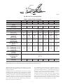
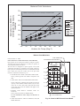
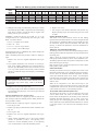
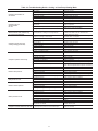
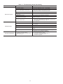
Required Liquid Line Temperature for a Specific Subcooling (R-410A)
Required Subcooling oF (oC)
o
Model Size
75 (24)
82 (28)
85 (29)
95 (35)
105 (41)
Pressure
(psig)
024
030
036
042
048
060
10.3 ( 5.7 )
9.3 ( 5.2 )
17.6 ( 9.8 )
12.8 ( 7.1 )
17.5 ( 9.7 )
13.7 ( 7.6 )
9.8 ( 5.4 )
8.8 ( 4.9 )
16.8 ( 9.3 )
12.7 ( 7.1 )
16.9 ( 9.4 )
13 ( 7.2 )
9.4 ( 5.2 )
8.6 ( 4.8 )
16.5 ( 9.2 )
12.7 ( 7.1 )
16.6 ( 9.2 )
13 ( 7.2 )
9(5)
7.8 ( 4.3 )
15.4 ( 8.6 )
12.6 ( 7 )
15.7 ( 8.7 )
14.5 ( 8.1 )
8.6 ( 4.7 )
7 ( 3.9 )
14.3 ( 7.9 )
12.6 ( 7 )
14.8 ( 8.2 )
11.5 ( 6.4 )
Charging Procedure
1- Measure Discharge line pressure by attaching a gauge to the service port.
2- Measure the Liquid line temperature by attaching a temperature sensing
device to it.
3- Insulate the temperature sensing device so that the Outdoor Ambient
doesn’t affect the reading.
4- Refer to the required Subcooling in the table based on the model size and
the Outdoor Ambient temperature.
5- Interpolate if the Outdoor ambient temperature lies in between the table
values. Extrapolate if the temperature lies beyond the table range.
6- Find the Pressure Value in the table corresponding to the the measured
Pressure of the Compressor Discharge line.
7- Read across from the Pressure reading to obtain the Liquid line
temperature for a required Subcooling
8- Add Charge if the measured temperature is higher than the table value.
50XZ500174
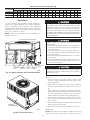
o
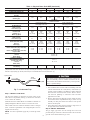
Required Subcooling ( C)
Required Subcooling ( F)
Outdoor Ambient Temperature
189
196
203
210
217
224
231
238
245
252
260
268
276
284
292
300
309
318
327
336
345
354
364
374
384
394
404
414
424
434
444
454
464
474
484
494
504
514
524
534
Pressure
5
61
63
66
68
70
72
74
76
77
79
81
83
85
87
89
91
93
95
97
99
101
103
105
107
108
110
112
114
116
118
119
121
123
124
126
127
129
131
132
134
10
56
58
61
63
65
67
69
71
72
74
76
78
80
82
84
86
88
90
92
94
96
98
100
102
103
105
107
109
111
113
114
116
118
119
121
122
124
126
127
129
15
51
53
56
58
60
62
64
66
67
69
71
73
75
77
79
81
83
85
87
89
91
93
95
97
98
100
102
104
106
108
109
111
113
114
116
117
119
121
122
124
20
46
48
51
53
55
57
59
61
62
64
66
68
70
72
74
76
78
80
82
84
86
88
90
92
93
95
97
99
101
103
104
106
108
109
111
112
114
116
117
119
25
41
43
46
48
50
52
54
56
57
59
61
63
65
67
69
71
73
75
77
79
81
83
85
87
88
90
92
94
96
98
99
101
103
104
106
107
109
111
112
114
(kPa)
1303
1351
1399
1448
1496
1544
1593
1641
1689
1737
1792
1848
1903
1958
2013
2068
2130
2192
2254
2316
2378
2440
2509
2578
2647
2716
2785
2854
2923
2992
3061
3130
3199
3268
3337
3406
3475
3544
3612
3681
3
16
17
19
20
21
22
23
24
25
26
27
29
30
31
32
33
34
35
36
37
38
39
40
41
42
44
45
46
47
48
48
49
50
51
52
53
54
55
56
56
6
13
15
16
17
18
19
20
21
22
23
25
26
27
28
29
30
31
32
33
34
35
36
38
39
40
41
42
43
44
45
46
47
48
48
49
50
51
52
53
54
8
11
12
13
14
15
16
18
19
20
21
22
23
24
25
26
27
28
29
31
32
33
34
35
36
37
38
39
40
41
42
43
44
45
46
47
47
48
49
50
51
11
8
9
10
11
13
14
15
16
17
18
19
20
21
22
23
24
26
27
28
29
30
31
32
33
34
35
36
37
38
39
40
41
42
43
44
45
46
46
47
48
14
5
6
8
9
10
11
12
13
14
15
16
17
19
20
21
22
23
24
25
26
27
28
29
30
31
32
33
34
35
36
37
38
39
40
41
42
43
44
45
45
C03027
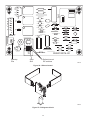
Fig. 20—Cooling Charging Table-Subcooling
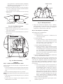
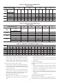
BLOWER
HOUSING
2 SETSCREWS
(HIDDEN)
C99085
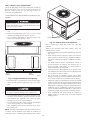
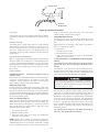
Fig. 23—Removal of Motor and Blower Wheel
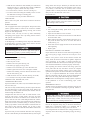
C99086
season. For the first heating season, inspect blower wheel bimonthly to determine proper cleaning frequency.
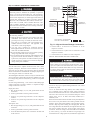
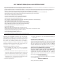
Fig. 24—Burner Rack Removed
1. Remove unit access panel (See Fig. 22).
To inspect blower wheel, remove draft hood assembly. Shine a
flashlight into opening to inspect wheel. If cleaning is required,
remove motor and wheel as follows:
2. Remove the 7 screws that attach induced-draft motor mounting plate to blower housing (See Fig. 23).
25