1
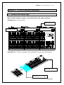
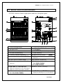
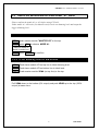
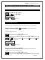
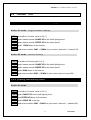
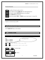
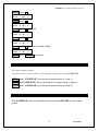
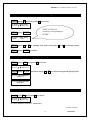
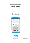
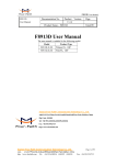
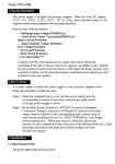
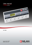
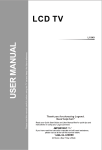
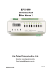
CX-2401
EXTENSIBLE
MODULE
DESIGN
24CH. Modular Dimmer Console
【User Manual】
Lite-Puter Enterprise Co., Ltd.
Website: http://www.liteputer.com.tw
E-mail: [email protected]
CX-2401 24ch. ModularDimmer Console
INDEX :
Chapter 1. CX-2401 introduction................................................................. 2
1-1 CX-2401 Features ............................................................................... 3
1-2 CX-2401 Regulation ............................................................................ 3
Chapter 2. CX-2401 module installation
2-1 Standard and extend type................................................................... 4
2-2 Master module & Slave module front panel discription.................... 5
2-3 Master module & Slave module rear panel discription ..................... 6
Chapter 3. Operation
3-1
3-2
3-3
3-4
3-5
3-6
3-7
3-8
3-9
A1 & A2 .............................................................................................. 7
How to set and execute the scene under A1 mode............................ 8
How to set and execute the scene under A2 mode............................ 9
How to stop all the output for a while .............................................. 10
How to clear all the output ................................................................ 10
Chaser type ........................................................................................ 11
How to stop chasing.......................................................................... 12
Scenes X-FADE................................................................................. 12
Additional functions to F3 function key.....................................14-15
1
Lite-Puter
CX-2401 24ch. ModularDimmer Console
Chapter 1.
CX-2401 introduction
To change scene quickly.
Do you have the experience?
We are often asked to operate lighting immediately, but the show has finished before you
know how to use the console. CX-2401 will be an ideal dimmer console to change the scene
quickly and meet your need.
To use conveniently by module design
CX-2401 dimmer console is designed to be a simple and easy operation machine. Because it
is absolutely operated by one channel to one channel mode, a big control panel is necessary.
Therefore, module design can meet all you need and be used in the big stage or the small club.
Furthermore, Cx-2401 output can be patched to 512 channels through LITE PUTER DP-11
DMX patch panel to make operate easily.
Standard Set 1 Master + 2 Slaves (12 ch. X 2) to control 24 ch.
Extended Set 1 Master + 2 ~ 7 Slaves (12ch. X 2 ~ 7) to make 10 pieces of
dimmer module and control 84 ch.
2
Lite-Puter
CX-2401 24ch. ModularDimmer Console
1-1
CX-2401 features
l DMX signal interface:DMX-512 (512 CH.)
l Channel control:
Standard set: to control 24 ch.
Extended set: 7 dimmer modules can be extended at most and control 84 ch.
l 120 Scenes
l Call out the scene quickly by HOT KEY or VR.
Standard set: 24 VR & HOT KEY to call out scene 1 ~ 24.
Extended set: each dimmer module can call out 12 scenes by VR or HOT KEY
and total 120 scenes at most.
l 2 independent cross faders “A” and “B”
l X-FADE
Each program file can be programmed up to 120 steps
each step corresponds to a certain scene
l MIDI /AUDIO/ CHASER functions.
1-2 CX-2401 regulation
l
Power supply:100-240VAC / 50-60Hz
l
DMX output/input:DMX-512 / 1990 protocol
l
DMX output channel:512 CH.
l
DMX connector:XLR 5-pin
l
AUDIO input:200 mV max. Microphone inside.
l
Goose neck light conntector:XLR 3pin, DC+12V 250mA.
l
Dimension:
STANDARD:720 x 380 x 90mm (LxWxH)
MASTER: 240 x 380 x 90mm (LxWxH)
SLAVE:
240 x 380 x 90mm (LxWxH)
3
Lite-Puter
CX-2401 24ch. ModularDimmer Console
Chapter 2. CX-2401 module installation
2-1 Standard and extend type
Merit: flexible channel number, easy maintenance and update software.
Standard set: to control 24 ch.
MASTER x 1 set
SLAVE x 2 sets
SLAVE-24 FADER PANEL
SLAVE-24 FADER PANEL
CX-2401 MASTER CONTROL PANEL
Extended set: 7 dimmer modules can be extended at most and control 84 ch.
MASTER x
SLAVE x 2
4
1set
~ 7 sets
Lite-Puter
CX-2401 24ch. ModularDimmer Console
2-2 MASTER / SLAVE front panel description
CX-2401 consists of mater (right photo) and slave (left photo) parts:
SLAVE-24 FADER PANEL
CX-2401 MASTER CONTROL PANEL
(1) Goose neck light switch
(2) Goose neck connector (DC+12V 250mA)
(3) BLANK switch
(4) LCD display
(5) F1~F4 function key
(6) MASTER VR (clearance key)
(7) ENTER confirmation key
(8) Forth / Back key
(9) CANCEL clearance output key
(10) Master VR for A scene.
(VR#A)
(12) VR for dimming level under AUDIO
function.
(11) Master VR for B scene.
(VR#B)
(13) VR for speed of channel output
(14) X-FADER / clearance key
(15) VR for dimming level under CHASE
(16) VR for channel dimming & scene output.
A1: (CH#1~CH#24)
function.
A2: (SC#1~SC#24)
(17) HOT KEY #1 ~ HOT KEY #24
(18) SPACE: for user’s memory.
Mode A1:dimming level for each channel.
Mode A2: quick scene output / FLASH
(19) VR for the dimming output of the scene. (20) HOT KEY #1 ~ HOT KEY #24
display the dimming level of each channel.
A1 / A2: (CH#1~CH#24)
5
Lite-Puter
CX-2401 24ch. ModularDimmer Console
2-3 MASTER/ SLAVE rear panel discription
MASTER rear panel
SLAVE rear panel
(1) Power Switch
(2) DMX-512 output
(3) DMX-512 output
(4) AC power socket:100-240 V AC
(5) Midi signal output
(6) Midi signal input
(7) Rs232 D type socket (9 Pin)
(8) Audio socket
(9) Power and signal connection socket
(10) Screws for fixing modules.
(11) Dip switch
6
Lite-Puter
CX-2401 24ch. ModularDimmer Console
Chapter 3. Operation
3-1 A1 & A2
CX-2401 is designed of A1 and A2 modes to change the scene immediately and
meet the user’s need.
SLAVE-24 FADER PANEL
Channels
Scenes
Channels
Channels
A1
Top line: the channel dimming level of A scene.
Bottom line: preset dimming level for B scene.
A2
Top line: to set and call out the scene.
Bottom line: display the real dimming output of the scene.
7
Lite-Puter
CX-2401 24ch. ModularDimmer Console
3-2
How to set and execute the scene under “A1” mode
Please confirm the mode (A1 or A2) before using CX-2401.
Under mode A1: A/B scene (24 channels each) can be set dimming level and output the
bigger dimming level .
3-2-1. To enter ” A1” mode
STEP-1:push master module "MASTER VR" to the top.
STEP-2:press
F1 to chooce MODE A1.
NOW IS MODE A1
SURE TO MODE A1?
STEP-3:press
ENTER to confirm.
3-2-2. To set dimming level for A/B scenes
STEP-1:Push slave module VR on top line to ideal dimming level.
STEP-2:Push slave module VR on bottom line to ideal level.
STEP-3:Push master module VR#A (on top line) to the top.
3-2-3. To execute A/B scene cross fader
Pull VR#A down to the bottom (0% output) and push VR#B up to the top (100%
output) at same time.
8
Lite-Puter
CX-2401 24ch. ModularDimmer Console
3-3 How to set and execute the scene under “A2” mode
3-3-1. To enter ”A2” mode
STEP-1:Push "MASTER VR" to the top.
STEP-2:Press F2 to chooseMODE A2.
NOW IS MODE A2
SURE TO MODE A2?
STEP-3:Press ENTER to confirm.
3-3-2. Setting the scene
120 scenes can be set and 24 HOT KEY & VR for calling out scene 1-24 immediately.
Method 1:to set scene 1-24 by F4 function key
120 scenes can be set at most.
STEP-1:push master module VR#A & VR#B to the top.
STEP-2:push slave module SC#1~SC#24 (top line) and CH#1~CH#24 (bottom line)
to ideal dimming level.
STEP-3:press F4 to choose the scene. ù:forth 1 scene ü:back 1 scene ÿ:forth
10 scenes ÷:back 10 scenes
RECORD TO :
Pressù ü+-1ÿ ÷+10
STEP-4:press ENTER to confirm.
Method 2:to set scene 1-24 by HOT KEY
Eg. Save many scenes and channels in scene1.
STEP-1:push master module VR#A 與 VR#B to the top.
STEP-2:push slave module SC#1~SC#24 and CH#1~CH#24 to ideal dimming level.
9
Lite-Puter
CX-2401 24ch. ModularDimmer Console
STEP-3:press master module F4 (REC.), and then press slave module
under SC#1.
HOT KEY
RECORD TO :
1
Pressù ü+-1ÿ ÷+10
Scene1 setting will be finished when Lcd displays the initial monitor.
NOW IS MODE A2
CX-2401 Ver: 1.0
3-3-3. To execute the scene
EG.: How to call out scene1
Method 1:push SC#1~SC#24 (dimming output)
Push SC#1 to call scene 1(0%~100%), and the led (bottom line) will display
the channels of scene1.
Method 2:call out by HOT KEY#1 ~ #24
(switch output)
Press HOT KEY #1 ~ #24 (top line) to call out scene 1 (switch output) and
leave the key to stop output.
3-4 How to ”stop” all the output for a while
Please press
BLANK key.
3-5 How to “clear” all the output
STEP-1:pull all slave module channels down to the bottom.
STEP-2:pull "MASTER VR"down to the bottom, and then press MASTER to clear all
channels ouput. (p.s. it is exceptional under x-fade & chase functions.)
10
Lite-Puter
CX-2401 24ch. ModularDimmer Console
3-6
“CHASER” TYPE
3-6-1. Call out the scenes to choose chasing type
Under A1 mode: single channel chasing
STEP-1:to confirm A1 mode. (refer to 3-2-1)
STEP-2:push master module CHASE VR to the ideal lighting level.
STEP-3:push master module SPEED VR to the ideal speed.
STEP-4:push” VR#A”down to the bottom.
STEP-5:push slave module CH#1 ~ CH#24 for your need. (channel 1~ channel 24)
Under A2 mode: scenes chasing
STEP-1:to confirm A2 mode.(refer 3-3-1)
STEP-2:push master module CHASE VR to the ideal lighting level.
STEP-3:push master module SPEED VR to the ideal speed.
STEP-4:push VR#A down to the bottom.
STEP-5:push slave module SC#1 ~ SC#24 for your need. (scene1~scene24)
3-6-2. Chasing controlled by audio
Under A1 mode:
STEP-1:to confirm A1 mode. (refer to 3-2-1)
STEP-2:push CHASE VR to the ideal lighting level.
STEP-3:pull SPEED VR down to the bottom.
STEP-4:push AUDIO VR to the top.
STEP-5:push slave module CH#1 ~CH#24 for your need. (channel 1 ~channel 24).
11
Lite-Puter
CX-2401 24ch. ModularDimmer Console
Under A2 mode:
STEP-1:to confirm A2 mode. (refer to 3-3-1)
STEP-2:push master module CHASE VR to the ideal lighting level.
STEP-3:pull master module SPEED VR down to the bottom.
STEP-4:push AUDIO VR up to the top.
STEP-5:push slave module SC#1 ~ SC#24 for your need.(scene 1~ scene 24).
3-6-3. Chasing controlled by MIDI
Output is controlled only by MIDI.
3-7
How to stop chasing
Pull "CHASE VR" down to the bottom.
3-8
Scenes X-FADE
3-8-1. Setting “X-FADE”
EG.:
STEP 1 = SCENE 2
STEP 2 = SCENE 4
STEP 3 = SCENE 6
120 steps at most.
ù
or ü:choose previous step or next step.
ÿ
or
÷:choose previous scene or next scene.
STEP-1:press F3 ,to set scene steps.
1.XFADE EDIT
P r e s s ù ü KEY Sel
STEP-2:press ENTER to confirm.
1.XFADE EDIT
STEP 1 =SC 1
12
Lite-Puter
CX-2401 24ch. ModularDimmer Console
STEP-3:press ÷
1.XFADE EDIT
STEP 1 =SC 2
STEP-4:press ù
1.XFADE EDIT
STEP 2 =SC 2
STEP-5:press ÷ two times
1.XFADE EDIT
STEP 2 =SC 4
STEP-6:press ù
1.XFADE EDIT
STEP 3 =SC 4
STEP-7:press ÷ two times to finish setting.
1.XFADE EDIT
STEP 3 =SC 6
STEP-8:press
ENTER to confirm.
3-8-2. Executing “X-FADE”
The same example as above:
To display scene 2, scene 4 and scene 6 dimming output by pressing X-FADE VR.
STEP-1:push "X-FADE VR" up to the top to output scene 2. (step 1)
STEP-2:pull "X-FADE VR" down to the bottom to output scene 4. (step 2)
STEP-3:push "X-FADE VR" up to the top to output scene 6. (step 3)
3-8-3. Stop “X-FADE”
Pull "X-FADE VR" down to the bottom and then press HOT KEY to stop x-fade
output.
13
Lite-Puter
CX-2401 24ch. ModularDimmer Console
3-9 Additional functions to F3 function key.
Press F3 and then press ù or ü to choose the functions.
3-9-1. Edit “X-FADE”
Referring 3-8
3-9-2. Setting channel level correspond to MIDI.
Basic MIDI format includes:
【CHANNEL】 (Correspond to different kinds of musical instrument)
【TONE】
(From 0 to 127)
【VELOCITY】 (From 0 to 127)
MIDI IN function:call out 120 scenes by ”TONE”.
MIDI interface can send out 16 different kinds of musical effect by installing different level
on CHANNEL (1-16). As a result of that, the MIDI-CHANNEL level in CX-2401 has to be
corresponding to the CHANNEL level of MIDI interface, then CX-2401 can receive the data
correctly from MIDI interface.
TONE can send 128 different kinds of digital code to CX-2401, which will divide 128 TONE
into 120 MIDI MEMORY, and each of those represents a “SCENE”.
STEP-1:press F3 and then press ù three times.
3.MIDI CHNL. SET
Press ù ü KEY Sel
STEP-2:press ENTER.
3.MIDI CHNL. SET
MIDI CHNL. =
1
STEP-3:pressù or üto adjust 1-16 channel level.
STEP-4:press ENTERto confirm.
14
Lite-Puter
CX-2401 24ch. ModularDimmer Console
3-9-3. To set “scene” level corresponding to “tone”
STEP-1:press F3 and then press ù two times
2.MIDI TONE EDIT
Press ù ü KEY Sel
TONE 1-TONE 128
STEP-2:press ENTER
are always corresponding to
SCENE 1
2.MIDI TONE EDIT
TONE
1=SC 1
STEP-3:press ù or ü to change tone level and press ÿ or ÷ to change scene
level.
STEP-4:press ENTERto confirm.
3-9-4. To set LCD background lighting level.
STEP-1:press
F3 ,and pressùfour times.
4.LCD BACKGROUND
Press ù ü KEY Sel
STEP-2:press ENTER ,and then press ù or ü,to adjust background lighting level.
4.LCD BACKGROUND
LIGHTLY
4.LCD BACKGROUND
BLACKLY
3-9-5. Inspection
Step-1:press F3 , and pressù five times.
5.E2M DATA INIT.
Press ù ü KEY Sel
p.s. the function is for Q.C. inspection.
CX-2401 [EUM-C]
15
Lite-Puter