1
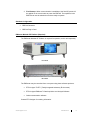
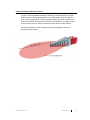
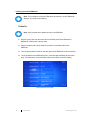
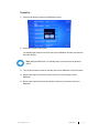
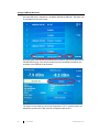
Model 7008 Series EMField™ Generator User Manual ETS-Lindgren Inc. reserves the right to make changes to any products herein to improve functioning or design. Although the information in this document has been carefully reviewed and is believed to be reliable, ETS-Lindgren does not assume any liability arising out of the application or use of any product or circuit described herein; nor does it convey any license under its patent rights nor the rights of others. All trademarks are the property of their respective owners. © Copyright 2015 by ETS-Lindgren Inc. All Rights Reserved. No part of this document may be copied by any means without written permission from ETS-Lindgren Inc. Trademarks used in this document: The ETS-Lindgren logo is a registered trademark of ETS-Lindgren Inc., and EMField, TILE!, EMCenter, EMQuest, Calibration Services Plus!, and EMPower are trademarks of ETS-Lindgren Inc. Revision Record MANUAL,EMFIELD GENERATOR | Part #399396, Rev. A Revision Description Date A Initial Release September, 2015 ii ets-lindgren.com Table of Contents Notes, Cautions, and Warnings ........................................................................ vi Safety Information ............................................................................................. vi 1.0 Introduction ................................................................................................... 7 EMField Plug-in Card ......................................................................................................... 7 System Benefits .................................................................................................................. 8 System Safety..................................................................................................................... 8 Standard Configuration ....................................................................................................... 9 EMCenter Modular RF Platform (Required) ....................................................................... 9 Optional Items................................................................................................................... 10 Service Procedures .......................................................................................................... 10 Contacting ETS-Lindgren ........................................................................................... 10 Sending a Component for Service ............................................................................. 10 Calibration Services ................................................................................................... 11 2.0 Specifications.............................................................................................. 13 Power Specifications ........................................................................................................ 13 Performance Specifications .............................................................................................. 13 Safety Specifications ........................................................................................................ 14 Physical Specifications ..................................................................................................... 14 Environmental Specifications ........................................................................................... 14 3.0 Installation ................................................................................................... 15 Plug-In Card Installation ................................................................................................... 15 Hardware Configuration .................................................................................................... 16 Field Polarization and Reference Point ............................................................................ 17 4.0 Operation ..................................................................................................... 19 Operations: Warnings & Precautions ............................................................................... 19 Powering On and Off EMCenter ....................................................................................... 20 Power On ................................................................................................................... 20 Power Off ................................................................................................................... 21 Using the EMField Generator ........................................................................................... 22 Remote Control of the EMField ........................................................................................ 23 5.0 EMField Command Set ............................................................................... 25 Commands ....................................................................................................................... 25 General Commands ................................................................................................... 25 ets-lindgren.com iii Power Meter Commands ........................................................................................... 28 Error Codes ...................................................................................................................... 29 Generic Error Codes .................................................................................................. 29 Module-Specific Error Codes: Amplifier ..................................................................... 29 Module-Specific Error Codes: Backplane .................................................................. 31 Module-Specific Error Codes: Plug-In Card ............................................................... 31 Appendix A: Standards .................................................................................... 33 Appendix B: Warranty ...................................................................................... 37 Scope and Duration of Warranties ................................................................................... 37 Warranty Exclusions ......................................................................................................... 38 Buyer’s Remedies ............................................................................................................ 38 Appendix C: EC Declaration of Conformity .................................................... 41 iv ets-lindgren.com This page intentionally left blank. ets-lindgren.com v Notes, Cautions, and Warnings Note: Denotes helpful information intended to provide tips for better use of the product. CAUTION: Denotes a hazard. Failure to follow instructions could result in minor personal injury and/or property damage. Included text gives proper procedures. WARNING: Denotes a hazard. Failure to follow instructions could result in SEVERE personal injury and/or property damage. Included text gives proper procedures. Safety Information Refer to Manual: When product is marked with this symbol, see the instruction manual for additional information. If the instruction manual has been misplaced, download it from www.ets-lindgren.com, or contact ETS-Lindgren Customer Service. High Voltage: Indicates presence of hazardous voltage. Unsafe practice could result in severe personal injury or death. Protective Earth Ground (Safety Ground): Indicates protective earth terminal. You should provide uninterruptible safety earth ground from the main power source to the product input wiring terminals, power cord, or supplied power cord set. Waste Electrical and Electronic Equipment (WEEE) Directive: (European Union) At end of useful life, this product should be deposited at an appropriate waste disposal facility for recycling and disposal. Do not dispose of with household waste. Note: For warnings and precautions while operating the EMField, see page 19. vi ets-lindgren.com 1.0 Introduction The ETS-Lindgren Model 7008 Series EMField™ Generator is a unique, integrated solution for Radiated Immunity testing, including IEC/EN 61000-4-3. It combines an amplifier, directional couplers, and an antenna array into one remarkable, simplified design. Almost all of the generated power is converted into useable field strength. The supporting instrumentation (signal generator, laser probe controller, and EMField power supply) are plug-and-play card modules that insert into the back of the EMCenter™ Modular RF Platform, which is typically placed in the control room. The EMField is available in a variety of models: Model 7008-001: 6 GHz, 10 V/M Model 7008-002: 6 GHz, 3 V/M Model 7008-003: 3 GHz, 10 V/M Model 7008-004: 3 GHz, 3 V/M The EMField is air-cooled. Air is drawn in at the back and blown out along the external cooling ribs, through the side air outlets, and then out of the openings in the foam cones. The cooling system keeps the internal amplifiers at a constant operating temperature. Failure to meet the specified environmental temperature range might result in a too high or too low amplifier temperature. The power, RF input, and communication connection run through one coaxial cable. This cable is connected at the back to an N-type connector. The EMField has a standard 1/4–20 UNC-1B thread on the bottom. This can be used to mount on a tripod, antenna tower, or boom mount. EMField Plug-in Card The EMField includes a two-slot plug--in card (Model 7008-100) for the EMCenter. It combines power, RF input, and communication within the coaxial cable to the EMField. The plug-in card has a separate mains input connection to power the EMField. An SMA connector is used for the RF input and an N-type connector for the connection to the EMField. ets-lindgren.com Introduction 7 System Benefits Eliminate Power Loss—RF power loss is at a minimum, reducing energy consumption and eliminating the need for expensive, high-power amplifiers. Integrated Power Meters—Eliminates the need for separate external coupler and power meters. Easy to Use—By using only one coaxial cable for the transport of the RF signal, the communication signals and DC power supply are easy to set up; this saves time and costs, as well as reduces the risk of equipment damage due to incorrect equipment connections. Fully Compliant—Fully compliant with the international EMC immunity standards. These standards describe aspects such as the frequency, field strength, and homogeneity. High Value for Money—With the integrated coupler and power meters, is a complete EMC immunity testing setup; in addition, calibrations costs are reduced. EMCenter Integration—Allows for easy touchscreen operation and several control interfaces such as GPIB, Ethernet, and USB. For more information about the EMCenter, see page 9. System Safety The EMField will only be able to power on if all connections are properly made. In addition, the EMField will shut down immediately if the interlock of the EMCenter is triggered. The start-up procedure consists of three phases that ensure the safe use of the EMField. If the EMField is not connected correctly, or if there is any other irregularities, the safety measures of this startup procedure will be triggered. In each phase the supply power is increased, building up to the DC power needed for normal usage. 1. Probing Stage—When the startup command is given to the EMField, a safe probe signal is sent through the coaxial cable to the EMField. If the EMField does not respond correctly to the probe signal, the startup procedure is aborted. This probe signal is harmless to other equipment and will therefore not cause defects to other instruments in case of an incorrect connection. 2. Communication Stage—After a successful probing phase, the plug-in card will attempt to communicate with the intelligent backplane of the EMField. If the intelligent backplane does not respond, the startup procedure is aborted. 8 Introduction ets-lindgren.com 3. Final Startup—When communication is established, the final DC power will be applied on the coaxial cable to power the EMField. The amplifiers in the EMField can now be switched on and are ready to operate. Standard Configuration EMField Generator EMField Plug-in Card EMCenter Modular RF Platform (Required) The EMCenter Modular RF Platform is required for operation, and is sold separately. Front Panel Back Panel The EMCenter may be controlled from a computer using these software products: ETS-Lindgren TILE!™ (Totally Integrated Laboratory Environment) ETS-Lindgren EMQuest™ Data Acquisition and Analysis Software Other test automation software Contact ETS-Lindgren for ordering information. ets-lindgren.com Introduction 9 Optional Items Transport Case—Designed for on-site and facility transports. The EMField must be stored in the transport case when it is shipped between locations. If the transport case is not used, the customer must provide an alternative and equal-or-better method of protection for the EMField. WARNING: The transport case is designed for short-distance transportation. It does not provide sufficient protection for air travel or other long-distance shipping. Additional or different (protective) packaging is needed in those situations The EMField might be damaged if the transport case is handled in a rough manner. Antenna Stinger Mount Boom—A custom-made antenna boom can be mounted on the back. It is 50 cm long and has a diameter of 40 mm. Coaxial N-Type Cable—A coaxial cable is used to connect the plug-in card with the EMField. The coaxial cable needs to be fitted with an N-type connector on both sides. The maximum allowed attenuation of the cable for proper system operation is 10 dB at 6 GHz. The selected cable also needs to be able to handle a DC current of 8 amps. Service Procedures CONTACTING ETS-LINDGREN Note: Please see www.ets-lindgren.com for a list of ETS-Lindgren offices, including phone and email contact information. SENDING A COMPONENT FOR SERVICE 1. Contact ETS-Lindgren Customer Service to obtain a Service Request Order (SRO). 2. Briefly describe the problem in writing. Give details regarding the observed symptom(s) or error codes, and whether the problem is constant or intermittent in nature. Please include the date(s), the service representative you spoke with, and the nature of the conversation. Include the serial number of the item being returned. 3. Package the system or component carefully. If possible, use the original packing materials or carrying case to return a system or system component to ETS-Lindgren. 10 Introduction ets-lindgren.com CALIBRATION SERVICES Annual Calibration—For reliable and repeatable long-term performance, annual recalibration of your measuring device by an ETS-Lindgren experienced technician is recommended. The ETS-Lindgren calibration team will calibrate most any type or brand of measuring device. Additional information is available at www.ets-lindgren.com. Calibration Services Plus!™—Calibration Services Plus! is a customized, optional program to help you expertly maintain your test and measurement assets. It is designed to address the challenges of managing the calibration and repair of test and measurement components, including scheduling and planning to ensure peak performance. Additional information is available at www.ets-lindgren.com. ets-lindgren.com Introduction 11 This page intentionally left blank. 12 Introduction ets-lindgren.com 2.0 Specifications Power Specifications Supply Voltage: 115 VAC / 230 VAC Max Power Consumption: 7008-001: 400 W 7008-002: 300 W 7008-003: 300 W 7008-004: 200 W Performance Specifications 7008-001 7008-002 7008-003 7008-004 Frequency Range: 1 GHz – 6 GHz 1 GHz – 6 GHz 1 GHz – 3 GHz 1 GHz – 3 GHz TME Field*: 10 V/m 3V/m 10 V/m 3V/m Input Connector: N-Type Max Input Power to Reach TME Field: 0 dBm Number of Internal Power Meters: Power Meter Type: Directional Coupler: 2 (Forward & Reflected) Integrated EMPower Integrated * Three Meter Equivalent (TME) Field: 1.5m x 1.5m homogeneous field @ 3m according to IEC 61000-4-3 ets-lindgren.com Specifications 13 Safety Specifications Safety Circuit: Safe start & shutdown Cable (Dis)connect: Intrinsically safe Voltage: 50 VDC (Safe Voltage) Interlock: Hardware interlock Physical Specifications Connections: Tripod mount, 1/4–20 UNC Thread Length: 860 mm (33.8 in) Width: 250 mm (9.8 in) Height: 250 mm (9.8 in) Weight: 7008-001: 11 kg (24.2 lb) 7008-002: 10 kg (22.0 lb) 7008-003: 10 kg (22.0 lb) 7008-004: 9 kg (19.8 lb) Environmental Specifications Temperature Range: 10ºC – 40ºC (50ºF – 104ºF) Relative Humidity: 10% – 90% (non-condensing) 14 Specifications ets-lindgren.com 3.0 Installation CAUTION: Before connecting any components, follow the information provided in Safety Information on page vi. Plug-In Card Installation CAUTION: The EMField plug-in card requires a protective earth connection. The mains power source for the equipment must supply an uninterrupted safety ground to the IEC input connector. Note: Due to the width of the EMField plug-in card, two consecutive empty slots are required for installation. 1. Determine in which empty slot(s) in the EMCenter™ Modular RF Platform you want to install the EMField™ Plug-in Card. Looking at the back of the EMCenter, the slots are numbered 1 through 7 from left to right. 2. Remove the blank panel from the slot by removing the two screws at the top of the blank panel and the two screws at the bottom 3. Carefully insert the EMField card into the slot(s) of the EMCenter. Tighten the four screws. 4. Turn on the EMCenter. The EMCenter will automatically detect the newly-installed EMField card. 5. Depending on the test setup requirements, connect coaxial cables to the relay connections on the back panel of the EMCenter. 6. Connect the EMCenter to a personal computer using USB, RS 232, Ethernet, or IEEE (optional). 7. Plug the interlock into the connector on the back of the EMCenter. The card installation is complete. You can control EMField through the EMCenter touchscreen, with ETS-Lindgren TILE!™ (Totally Integrated Laboratory Environment), ETS-Lindgren EMQuest™ Data Acquisition and Analysis Software, and other test automation software packages. Contact ETS-Lindgren for additional information. ets-lindgren.com Installation 15 Hardware Configuration The hardware configuration is carried out in the following steps: 1. Make sure that all connections to the plug-in card are made: Connect a suitable N-type coaxial cable from the plug-in card to the Model 7008 Series EMField Generator and connect a coaxial cable from a RF signal generator to the RF input of the plug-in card. Please note that the maximum field is reached at an input power between -10 dBm and 0 dBm, depending on the frequency response and attenuation of the N-type cable used. 2. Make sure that the remote interlock connection of the EMCenter is closed. 3. Plug the mains cords into the mains inlet of the EMCenter and the mains inlet of the plug-in card. 4. Switch the main power switches on both mains inlets to the ON position. 5. Touch the touchscreen on the front panel of the EMCenter to activate the EMField. The system is now ready to be used. 16 Installation ets-lindgren.com Field Polarization and Reference Point In order to perform radiated immunity measurements, standards require a certain distance from the field generating antenna to the Equipment Under Test (EUT). In most immunity setups the tip of the transmitting antenna is used to determine the distance to the EUT. Since the actual antenna of the EMField is not visible, a small hole in the nose of the is used as a reference point to determine this distance. For most test setups it is also necessary to know the polarization of the field generated by the antenna. ets-lindgren.com Installation 17 This page intentionally left blank. 18 Installation ets-lindgren.com 4.0 Operation CAUTION: Before placing into operation, follow the information provided in Safety Information on page vi. Operations: Warnings & Precautions CAUTION: Never use the EMField without a protective earth connection. CAUTION: Please make sure that the airflow through the in- and outlets of the EMField are not restricted to maintain a constant temperature. The cooling system is designed to operate in the specified operating temperature range. CAUTION: Verify that your mains voltage is within the operating range of the equipment. CAUTION: To maximize safety, the EMField will only power on when all connections are properly made. In addition, the EMField will shut down if the interlock of the EMCenter is triggered. CAUTION: Please use a suitable coaxial cable to connect the PSU plug-in card with the EMField: fitted with an N-type connector on both sides, maximum allowed attenuation of 10dB at 6GHz and able to handle a DC current of 8 amps. ets-lindgren.com Operation 19 Powering On and Off EMCenter Note: For information on using the EMCenter touchscreen, see the EMCenter Modular Test System User Manual. POWER ON Note: Verify all cards are installed correctly in the EMCenter. 1. Plug the power cord from the mains inlet on the back panel of the EMCenter™ Modular RF Platform into a power outlet. 2. Plug the interlock jack into the interlock connector on the back panel of the EMCenter. 3. Turn the power switch located on the back panel of the EMCenter to the on position. 4. Touch anywhere on the EMCenter screen. It will take approximately 20 seconds to boot. The Information screen will flash, and then the Home screen will display. Sample EMCenter Home Screen 20 Operation ets-lindgren.com POWER OFF 1. Press the Off button located on the EMCenter screen. 2. Press OK to switch off the system. The standby light located on the front panel of the EMCenter will flash, and then will illuminate steadily. Note: When the EMCenter is in standby mode, touch the screen anywhere to reboot. 3. Turn the power switch located on the back panel of the EMCenter to the off position. 4. Remove the power cord from the power connector on the back panel of the EMCenter. 5. Remove the interlock jack from the interlock connector on the back panel of the EMCenter. ets-lindgren.com Operation 21 Using the EMField Generator Once the EMCenter is switched on, the Model 7008 Series EMField™ Generator can be activated from the main screen. By pressing the status-button proceeded by the Ack-button, the start-up procedure of the EMField will begin. Once this procedure has been completed successfully, the amplifiers in the EMField will be powered. The system is now heating up to its final temperature of 75°C. It will be ready to be switched to operate once it has reached a temperature above 50°C. 22 Operation ets-lindgren.com In the EMField control screen, the parameters of the system can be read. In order to generate an EM-field, the system must be switched to operate. It is important to enter the frequency of the generator driving the EMField to read the correct power meter level. Entering the actual frequency will automatically correct for the frequency dependent coupler and power meter response inside the amplifiers. Normal operating parameters are: Amplifier temperature: 75°C +/- 5°C EMField DC voltage: +50Vdc EMField current: 5 to 8 A max Remote Control of the EMField The EMField can be controlled remotely through the interfaces of the EMCenter. The exact communication protocol can be found in the EMCenter Modular Test System User Manual. The specific commands for the EMField begin on page 25. ets-lindgren.com Operation 23 This page intentionally left blank. 24 Operation ets-lindgren.com 5.0 EMField Command Set Commands GENERAL COMMANDS Command ID_NUMBER? LOCAL VERSION_HW? Description / Response Returns unique identifier number. Reply (for example): ‘1.58.95.146.21.0.0.124’ Return to local mode, the local display is used to set items. Reply: ‘OK’ Returns the hardware version. Reply (for example): ‘2’ Returns the ID of the system. *IDN? Reply (for example): ‘ETS-Lindgren, EMField 7008-100, x.x.x’ Reset the module. This will: RESET Clear all errors Clear all occurred crowbars Reset the filter to filter 1 Reset the frequency to 3 GHz Set the amplifier to standby mode, if this fails an error is replied Reply: ‘OK’ or error code CLEAR All errors are cleared and crowbars are reset. Reply: ‘OK’ Get the state of the mains. MAINS? Reply: ‘1’ = ON Reply: ‘0’ = OFF Turn the main power ON or OFF. MAINS<space><value> <value> = ‘ON’ or ‘OFF’ Reply: ‘OK’ or error code STANDBY ets-lindgren.com Set the EMField in the standby mode. (FETs are biased). Reply: ‘OK’ or error code EMField Command Set 25 Command OPERATE Description / Response Set the EMField in the operate mode (RF path opened). Reply: ‘OK’ or error code Returns in which mode the EMField is. MODE? Reply (for example): ‘Operate’ CURRENT? Returns the current measured by the plug-in card (in ampere). Reply (for example): ‘1.2’ TEMP? 26 Returns the temperature (in degrees Celsius). Reply (for example): ’23.6’ EMField Command Set ets-lindgren.com Command Description / Response Returns a number which indicates what kind of error is occurred. This includes the following replies: STATUS? ‘0’ = No error ‘1’ = 3.3V error ‘2’ = 5V error ‘4’ = 10V error ‘8’ = -10V error ‘16’ = 50V error ‘32’ = current driver 3 error ‘64’ = current final error ‘128’ = temperature error ‘256’ = power error ‘512’ = driver fet adjustment error ‘1024’ = final fet adjustment error ‘2048’ = Oven too cold ‘4096’ = Oven too hot ‘8192’ = memory error ‘16384’ = driver vGate min limit ‘32768’ = driver vGate max limit ‘65536’ = driver adjustment timed out ‘131072’ = final vGate min limit ‘262144’ = final vGate max limit ‘524288’ = final adjustment timed out Some numbers represent multiple (of the previously mentioned) errors occurring at ones. For example, reply: ets-lindgren.com ‘3’ = error 1 and 2 = 3.3V and 5V error ‘5’ = error 1 and 4 = 3.3V and 10V error ‘6’ = error 2 and 4 = 5V and 10V error Etc. EMField Command Set 27 POWER METER COMMANDS Command Description / Response Get measure power level (in dBm). POW<value>? <value> = FWD or RFL. Reply (for example): ‘-12.34’ FREQUENCY? MIN FREQUENCY? MAX FREQUENCY<space> <value> Get the minimal frequency (in Hz). Reply (for example): ‘1000000000’ Get the maximum frequency (in Hz). Reply (for example): ‘6000000000’ Set the frequency. <value> = frequency (in Hz), for example: 500000000 Reply: ‘OK’ or ‘ERROR’ FREQUENCY? FILTER? MIN FILTER? MAX FILTER AUTO Get the frequency (in Hz). Reply (for example): ‘500000000’ Get the minimal meter filter. Reply (for example): ‘0’ Get the maximum meter filter. Reply (for example): ‘7’ Set filter to automatic. Reply: ‘OK’ Set the filter. FILTER<space><value> <value> = 1,2,3,4,5,6 or 7 Reply: ‘OK’ or ‘ERROR’ FILTER? 28 Get the current filter. Reply (for example): ‘1’ EMField Command Set ets-lindgren.com Error Codes The following tables show the generic error codes and the product specific error codes for the Model 7008 Series EMField™ Generator. This includes the error codes for the amplifier, backplane, and plug-in card that are part of the EMField system. GENERIC ERROR CODES Error Code Description 1 Wrong command 2 Parameter too high 3 Parameter too low 4 Invalid parameter 5 Buffer overflow 6 Already in progress 7 Parity error MODULE-SPECIFIC ERROR CODES: AMPLIFIER Error Code Description 500 Already in standby 501 Already in operate 502 Already in off 503 Not in standby 504 Hardware failure 506 Out of specification 507 Power measurement, frequency not set 508 Power measurement, over range 509 Power measurement, under range 510 Power measurement, no calibration data 511 No error logs available ets-lindgren.com EMField Command Set 29 Error Code Description 512 Not for customer! (Null pointer) 513 First send the startup command 514 Already started 515 Regulating FET 516 3V3 out of range 517 5V out of range 518 10V out of range 519 -10V out of range 520 50V out of range 521 Driver current out of range 522 Final current out of range 523 Temperature out of range 524 Power out of range 525 Driver fet adjustment error 526 Final fet adjustment error 527 Going to standby 528 Going to operate 529 Going to off 530 Oven too cold 531 Oven too hot 532 Calibrating busy 533 Power not updated 30 EMField Command Set ets-lindgren.com MODULE-SPECIFIC ERROR CODES: BACKPLANE Error Code Description 551 Communication busy 552 Amplifier error 553 Amplifier wrong *IDN 554 Amplifier wrong answer 555 Amplifier time-out 556 Amplifier wrong mode 557 No amplifier connected 558 Received command length are no digits 559 Received command length incorrect MODULE-SPECIFIC ERROR CODES: PLUG-IN CARD Error Code Description 504 Hardware failure 575 Communication busy 576 Communication time-out 577 Power supply already on 578 Power supply off 579 Incorrect impedance 580 Impedance short 581 Impedance open 582 External unit is not connected 583 Unknown error 584 SW update – 50V backplane not off 585 SW update – 50V backplane not on ets-lindgren.com EMField Command Set 31 Error Code Description 586 SW update – software download not started 587 SW update – sync retries failed 588 SW update – reboot unit failed 589 SW update – amplifier to off mode error 590 SW update – transparent mode on error 591 SW update – transparent mode off error 592 SW update –binary frame error 593 SW update –binary frame header error 594 SW update – binary frame header size error 595 Illegal backplane command length 596 Length error - received command length are no digits 597 Length error - received command length incorrect 598 Mains on sequence error – BPL 50V switch error 599 Mains on sequence error – AMP startup error 32 EMField Command Set ets-lindgren.com Appendix A: Standards The Model 7008-001 EMField™ Generator is a 10 V/m TME system. In other words: a field generator capable of generating 10 V/m at 3 meter with headroom for 80% AM. The peak field strength at 3 meter is therefore 18 V/m, resulting in 54 V/m at 1 meter distance. The tables on the following pages provide an overview of the standards for which the 10V/m TME system can be used: ets-lindgren.com Standards 33 34 Standards ets-lindgren.com 3 The distance between the transmitting antenna and the ME equipment or ME system may be reduced to 1 m. For compliance to EN61000-4-3 and required field amplitude it is necessary to test at a distance of 2 m. 4 EMField support measurements starting at 1000 MHz. ets-lindgren.com Standards 35 This page intentionally left blank. 36 Standards ets-lindgren.com Appendix B: Warranty Scope and Duration of Warranties Seller warrants to Buyer that the Products to be delivered hereunder will be (1) free from defects in material, manufacturing workmanship, and title, and (2) conform to the Seller’s applicable product descriptions and specifications, if any, contained in or attached to Seller’s quotation. If no product descriptions or specifications are contained in or attached to the quotation, Seller’s applicable product descriptions and specifications in effect on the date of shipment shall apply. The criteria for all testing shall be Seller’s applicable product specifications utilizing factory-specified calibration and test procedures and instruments. All product warranties, except the warranty of title, and all remedies for warranty failures are limited to three years. Product Warranted Duration of Warranty Period Model 7008 Series EMField Generator Three Year(s) Model 7008 Series EMField Plug-in Card Three Year(s) Any product or part furnished to Buyer during the warranty period to correct a warranty failure shall be warranted to the extent of the unexpired term of the warranty applicable to the repaired or replaced product. The warranty period shall commence on the date the product is delivered to Buyer; however, if Seller assembles the product, or provides technical direction of such assembly, the warranty period for such product shall commence on the date the assembly of the product is complete. Notwithstanding the foregoing, in the event that the assembly is delayed for a total of thirty (30) days or more from the date of delivery for any reason or reasons for which Seller is not responsible, the warranty period for such product may, at Seller’s options, commence on the thirtieth (30th) day from the date such product is delivered to Buyer. Buyer shall promptly inspect all products upon delivery. No claims for shortages will be allowed unless shortages are reported to Seller in writing within ten (10) days after delivery. No other claims against Seller will be allowed unless asserted in writing within thirty (30) days after delivery (or assembly if the products are to be assembled by Seller) or, in the case of alleged breach of warranty, within the applicable warranty period. ets-lindgren.com Warranty 37 Warranty Exclusions Except as set forth in any applicable patent indemnity, the foregoing warranties are exclusive and in lieu of all other warranties, whether written, oral, express, implied, or statutory. EXCEPT AS EXPRESSLY STATED ABOVE, SELLER MAKES NO WARRANTY, EXPRESS OR IMPLIED, BY STATUTE OR OTHERWISE, WHETHER OF MERCHANTABILITY OR FITNESS FOR ANY PARTICULAR PURPOSE OR USE OR OTHERWISE ON THE PRODUCTS, OR ON ANY PARTS OR LABOR FURNISHED DURING THE SALE, DELIVERY OR SERVICING OF THE PRODUCTS. THERE ARE NO WARRANTIES WHICH EXTEND BEYOND THE DESCRIPTION ON THE FACE HEREOF. Warranty coverage does not include any defect or performance deficiency (including failure to conform to product descriptions or specifications) which results, in whole or in part, from (1) negligent storage or handling of the product by Buyer, its employees, agents, or contractors, (2) failure of Buyer to prepare the site or provide an operating environmental condition in compliance with any applicable instructions or recommendations of Seller, (3) absence of any product, component, or accessory recommended by Seller but omitted at Buyer’s direction, (4) any design, specification, or instruction furnished by Buyer, its employees, agents or contractors, (5) any alteration of the product by persons other than Seller, (6) combining Seller’s product with any product furnished by others, (7) combining incompatible products of Seller, (8) interference with the radio frequency fields due to conditions or causes outside the product as furnished by Seller, (9) improper or extraordinary use of the product, or failure to comply with any applicable instructions or recommendations of Seller including maintenance, calibration and cleaning procedures and intervals, or (10) acts of God, acts of civil or military authority, fires, floods, strikes or other labor disturbances, war, riot, or any other causes beyond the reasonable control of Seller. This warranty does not include (1) batteries, (2) cables, (3) gasket, (4) fingerstock, or any item that is designed to be consumable. Seller does not warranty products of others which are not included in Seller’s published price lists. Buyer’s Remedies If Seller determines that any product fails to meet any warranty during the applicable warranty period, Seller shall correct any such failure by either, at its option, repairing, adjusting, or replacing without charge to Buyer any defective or nonconforming product, or part or parts of the product. Seller shall have the option to furnish either new or exchange replacement parts or assemblies. Warranty service shall be performed at the Seller’s factory, or the Buyer’s site at the sole discretion of the Seller. Within the warranty period, the Buyer shall be responsible for all transportation to the Seller’s factory, and the Seller shall be responsible for transportation of goods to the Buyer’s site. 38 Warranty ets-lindgren.com Within the contiguous 48 United States, warranty service performed during the applicable warranty period will be performed without charge to Buyer during Seller’s normal business hours. After the warranty period, service will be performed at Seller’s prevailing service rates. Subject to the availability of personnel, after-hours service is available upon request at an additional charge. Outside the contiguous 48 United States, travel and per diem expenses, when required, shall be the responsibility of the Buyer, or End User, whichever is applicable regardless of the warranty period. The remedies set forth herein are conditioned upon Buyer promptly notifying Seller within the applicable warranty period of any defect or non-conformance and making the product available for correction. The preceding paragraphs set forth Buyer’s exclusive remedies and Seller’s sole liability for claims based on failure of the products to meet any warranty, whether the claim is in contract, warranty, tort (including negligence and strict liability) or otherwise, and however instituted, and, upon the expiration of the applicable warranty period, all such liability shall terminate. IN NO EVENT SHALL SELLER BE LIABLE TO BUYER FOR ANY SPECIAL, INDIRECT, INCIDENTAL OR CONSEQUENTIAL DAMAGES OF ANY KIND ARISING OUT OF, OR AS A RESULT OF, THE SALE, DELIVERY, NON-DELIVERY, SERVICING, ASSEMBLING, USE OR LOSS OF USE OF THE PRODUCTS OR ANY PART THEREOF, OR FOR ANY CHARGES OR EXPENSES OF ANY NATURE INCURRED WITHOUT SELLER’S WRITTEN CONSENT DESPITE ANY NEGLIGENCE ON BEHALF OF THE SELLER. IN NO EVENT SHALL SELLER’S LIABILITIES UNDER ANY CLAIM MADE BY BUYER EXCEED THE PURCHASE PRICE OF THE PRODUCT IN RESPECT OF WHICH DAMAGES ARE CLAIMED. This agreement shall be construed in accordance with laws of the State of Texas. In the event that any provision hereof shall violate any applicable statute, ordinance, or rule of law, such provision shall be ineffective to the extent of such violation without invalidating any other provision hereof. Any controversy or claim arising out of or relating to the sale, delivery, non-delivery, servicing, assembling, use or loss of use of the products or any part thereof or for any charges or expenses in connection therewith shall be settled in Austin, Texas by arbitration in accordance with the Rules of the American Arbitration Association, and judgment upon the award rendered by the Arbitrator may be entered in either the Federal District Court for the Western District of Texas or the State District Court in Austin, Texas, all of the parties hereto consenting to personal jurisdiction of the venue of such court and hereby waive the right to demand a jury trial under any of these actions. ets-lindgren.com Warranty 39 This page intentionally left blank. 40 Warranty ets-lindgren.com Appendix C: EC Declaration of Conformity ETS-Lindgren Inc. declares these products to be in conformity with the following standards, following the provisions of EMC Directive 2004/108/EC and Low Voltage Directive 2006/95/EC: Model 7008 Series EMField Generator Emission: EN 61326-1:2006, Class A Electrical equipment for measurement, control, and laboratory use. Immunity: EN 61326-1:2006, Industrial level, performance criteria A Electrical equipment for measurement, control, and laboratory use. Safety: EN 61010-1:2010, Safety requirements for electrical equipment for measurement, control, and laboratory use. Technical Construction Files are available upon request. ets-lindgren.com EC Declaration of Conformity 41