1
Model 7007-001 / Model 7007-002
EMSense™
EMF Probe Plug-In Card
User Manual
Model 7007-001 EMSense card shown
ETS-Lindgren Inc. reserves the right to make changes to any product described herein in
order to improve function, design, or for any other reason. Nothing contained herein shall
constitute ETS-Lindgren Inc. assuming any liability whatsoever arising out of the application
or use of any product or circuit described herein. ETS-Lindgren Inc. does not convey any
license under its patent rights or the rights of others.
© Copyright 2015 by ETS-Lindgren Inc. All Rights Reserved. No part of this
document may be copied by any means without written permission from
ETS-Lindgren Inc.
Trademarks used in this document: The ETS-Lindgren logo is a registered trademark, and
EMCenter, EMSense, TILE!, and EMQuest are trademarks of ETS-Lindgren Inc.
Revision Record
MANUAL,EMSENSE | Part #399347, Rev. A
ii
Revision
Description
Date
A
Initial Release
March, 2015
www.ets-lindgren.com
Table of Contents
Notes, Cautions, and Warnings ............................................... vi
Safety Information....................................................................................... vi
1.0 Introduction .......................................................................... 9
Model 7007-001 EMSense for Battery-Operated Probes ............................ 9
Model 7007-002 EMSense for Laser-Powered Probes .............................. 10
EMCenter Modular RF Platform (Required) .............................................. 11
2.0 Maintenance ....................................................................... 13
Maintenance of Fiber Optics (If Used) ....................................................... 14
Replacement and Optional Parts .............................................................. 15
Service Procedures .................................................................................. 16
Contacting ETS-Lindgren .................................................................. 16
Sending a Component for Service..................................................... 16
3.0 Specifications ..................................................................... 17
Physical Specifications ............................................................................. 17
Environmental Specifications .................................................................... 17
4.0 EMSense Plug-In Card Installation .................................. 19
5.0 Operation ............................................................................ 21
EMSense Connectors and Indicators ........................................................ 21
Connectors ....................................................................................... 21
Indicator LEDs for 7007-002/Laser Only ........................................... 22
Powering On and Off EMCenter................................................................ 23
Power On.......................................................................................... 23
Power Off.......................................................................................... 24
Manual Control of EMSense ..................................................................... 25
Battery-Operated Field Probe Data: For 7007-001 Only .................... 25
Laser-Powered Field Probe Data: For 7007-002 Only ....................... 26
6.0 EMSense Command Set .................................................... 27
Information Transfer Protocol .................................................................... 27
Command Structure .......................................................................... 27
Example 1: Request a Reading ......................................................... 27
Example 2: Request a Reading ......................................................... 27
Commands for 7007-001 and 7007-002 .................................................... 28
www.ets-lindgren.com
iii
Additional Commands for 7007-002/Laser Only ........................................ 30
Error Codes .............................................................................................. 31
Appendix A: Warranty ............................................................. 33
Scope and Duration of Warranties ............................................................ 33
Warranty Exclusions ................................................................................. 34
Buyer’s Remedies..................................................................................... 35
Appendix B: EC Declaration of Conformity .......................... 39
iv
www.ets-lindgren.com
This page intentionally left blank.
www.ets-lindgren.com
v
Notes, Cautions, and Warnings
Note: Denotes helpful information intended to provide tips for better
use of the product.
Caution: Denotes a hazard. Failure to follow instructions
could result in minor personal injury and/or property
damage. Included text gives proper procedures.
Warning: Denotes a hazard. Failure to follow instructions
could result in SEVERE personal injury and/or property
damage. Included text gives proper procedures.
Safety Information
LASER HAZARD. Laser power up to 150 mW at 830 nm
may be accessible at the fiber connector of the laser.
However, the laser beam itself is not hazardous as the
interlock ensures that the exposure time will be less than
30 ms.
OR
vi
High Voltage: Indicates presence of hazardous voltage.
Unsafe practice could result in severe personal injury or
death.
www.ets-lindgren.com
Protective Earth Ground (Safety Ground): Indicates
protective earth terminal. You should provide
uninterruptible safety earth ground from the main power
source to the product input wiring terminals, power cord,
or supplied power cord set.
www.ets-lindgren.com
vii
This page intentionally left blank.
viii
www.ets-lindgren.com
1.0 Introduction
The ETS-Lindgren Model 7007-001 EMSense™ EMF Probe Plug-in Card is
designed for use with the following ETS-Lindgren battery-operated field probes;
the Model 7007-002 EMSense card is designed for use with the following
ETS-Lindgren laser-powered field probes (sold separately). Each EMSense card
can support one ETS-Lindgren probe.
Note: Contact ETS-Lindgren for information on ordering probes.
For complete information on ETS-Lindgren field probes, see the
EMC Field Probes User Manual included with the probe.
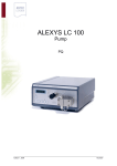
Model 7007-001 EMSense for Battery-Operated Probes
HI-6022
www.ets-lindgren.com
HI-6053
HI-6005
Introduction
9
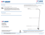
Model 7007-002 EMSense for Laser-Powered Probes
HI-6122
HI-6153
HI-6105
EMSense is fully supported by ETS-Lindgren TILE!™ (Totally Integrated
Laboratory Environment), ETS-Lindgren EMQuest™ Data Acquisition and
Analysis Software, and other test automation software packages. Contact
ETS-Lindgren for additional information.
10
Introduction
www.ets-lindgren.com
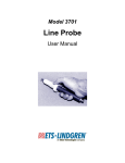
EMCenter Modular RF Platform (Required)
The EMCenter™ Modular RF Platform is required for operation, and is sold
separately.
Front Panel
Back Panel
The EMCenter may be controlled from a computer using these
software products:
ETS-Lindgren TILE!™ (Totally Integrated Laboratory Environment)
ETS-Lindgren EMQuest™ Data Acquisition and Analysis Software
Other test automation software
Contact ETS-Lindgren for ordering information.
www.ets-lindgren.com
Introduction
11
This page intentionally left blank.
12
Introduction
www.ets-lindgren.com
2.0 Maintenance
CAUTION: Before performing any maintenance, follow the
information provided in Safety Information on page vi.
WARNING: Maintenance of the EMSense system is limited
to external components such as cables or connectors.
WARRANTY
If you have any questions concerning
maintenance, contact ETS-Lindgren
Customer Service.
Note: For maintenance information for ETS-Lindgren field probes,
see the EMC Field Probes User Manual included with the probe.
www.ets-lindgren.com
Maintenance
13
Maintenance of Fiber Optics (If Used)
Fiber optic connectors and cables can be damaged from airborne particles,
humidity and moisture, oils from the human body, and debris from the connectors
they plug into. Always handle connectors and cables with care, using the
following guidelines.
CAUTION: Before performing any maintenance,
disconnect the fiber optic cables from the unit and turn off
power.
When disconnecting fiber optic cables, apply the included
dust caps to the ends to maintain their integrity.
Before connecting fiber optic cables, clean the connector
tips and in-line connectors.
Before attaching in-line connectors, clean them with
moisture-free compressed air.
Failure to perform these tasks may result in damage to the
fiber optic connectors or cables.
14
Maintenance
www.ets-lindgren.com
Replacement and Optional Parts
Note: ETS-Lindgren may substitute a similar part or new
part number with the same functionality for another
part/part number. Contact ETS-Lindgren for questions about
part numbers and ordering parts.
Following are the part numbers for ordering replacement or optional parts for the
EMSense™ EMF Probe Plug-in Card.
Part Description
Part Number
EMSense EMF Probe
Plug-in Card for
Battery-Operated Probes
7007-001: EMSense EMF Probe Plug-in Card,
Battery
EMSense EMF Probe
Plug-in Card for
Laser-Powered Probes
7007-002: EMSense EMF Probe Plug-in Card,
Laser
www.ets-lindgren.com
Maintenance
15
Service Procedures
CONTACTING ETS-LINDGREN
Note: Please see www.ets-lindgren.com for a list of ETS-Lindgren
offices, including phone and email contact information.
SENDING A COMPONENT FOR SERVICE
16
1.
Contact ETS-Lindgren Customer Service to obtain a Service Request
Order (SRO).
2.
Briefly describe the problem in writing. Give details regarding the
observed symptom(s) or error codes, and whether the problem is
constant or intermittent in nature. Please include the date(s), the
service representative you spoke with, and the nature of the
conversation. Include the serial number of the item being returned.
3.
Package the system or component carefully. If possible, use the
original packing materials or carrying case to return a system or
system component to ETS-Lindgren.
Maintenance
www.ets-lindgren.com
3.0 Specifications
Note: For ETS-Lindgren field probe specifications, see the
EMC Field Probes User Manual included with the probe.
Physical Specifications
Exterior Dimension:
1 slot
Environmental Specifications
Temperature Range:
0°C to 35°C (32°F to 95°F)
Relative Humidity:
10% to 90% (non-condensing)
www.ets-lindgren.com
Specifications
17
This page intentionally left blank.
18
Specifications
www.ets-lindgren.com
4.0 EMSense Plug-In Card Installation
CAUTION: : Before connecting any components, follow
the information provided in Safety Information on page vi.
CAUTION: The EMSense card is designed to be used
ONLY with the EMCenter. Do not use the card in
combination with any other system.
1.
Determine in which empty slot in the EMCenter™ Modular RF Platform
you want to install the EMSense™ EMF Probe Controller Plug-in Card.
You may use slots 1 through 7, numbered from left to right as you look
at the back of the EMCenter.
2.
Remove the blank panel from the slot by removing the two screws at
the top of the blank panel and the two screws at the bottom.
3.
Carefully insert the EMSense card into the slot of the EMCenter.
Tighten the four screws.
4.
Turn on the EMCenter. The EMCenter will automatically detect the
newly-installed EMSense card.
5.
Place the field probe in the location where the field strength is to be
measured.
6.
Connect the probe to the EMSense card.
7.
Connect the EMCenter to a personal computer using USB, RS-232,
Ethernet, or IEEE (optional).
8.
Plug the interlock into the connector on the back of the EMCenter.
The card installation is complete. You can control EMSense through the
EMCenter touchscreen, with ETS-Lindgren TILE!™ (Totally Integrated
Laboratory Environment), ETS-Lindgren EMQuest™ Data Acquisition and
Analysis Software, and other test automation software packages. Contact
ETS-Lindgren for additional information.
www.ets-lindgren.com
EMSense Plug-In Card Installation
19
This page intentionally left blank.
20
EMSense Plug-In Card Installation
www.ets-lindgren.com
5.0 Operation
CAUTION: Before placing into operation, follow the
information provided in Safety Information on page vi.
CAUTION: Prior to operation, verify that the mains voltage
is within the operating range of the equipment.
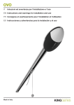
EMSense Connectors and Indicators
CONNECTORS
Note: Model 7007-002 for laser-powered probes includes additional
indicators; see page 22 for more information.
Transmit (yellow)
Receive (white)
Model 7007-001 EMSense card shown;
connectors may vary for Model 7007-002
www.ets-lindgren.com
Operation
21
INDICATOR LEDS FOR 7007-002/LASER ONLY
LASER HOT (red)
Constant On:
This is a warning that the laser is running too hot and the
system should be checked. Dirty fiber ends, poor in-line
connections, or damaged fiber optic cables are among the
causes of a LASER HOT warning. The system should be
shut down as soon as possible, and the cause of the
additional heat investigated. Continuing to run in a
LASER HOT state may reduce the life of the laser.
Flash:
This is an indication that the laser current is approaching
0.8 mA. During the initialization phase of the startup process
the probe receives more light; once the probe is powered and
communicating, the power is rolled back to a normal level. In
these instances the user may see LASER HOT flash on; this
is normal operation.
LASER OK (blue)
This is the normal status when probe communication is
established and laser light is provided to the probe for power.
RECEIVE (amber)
and
TRANSMIT (white)
These are illuminated during normal use.
RECEIVE indicates the communication between the probe
and the EMSense™ EMF Probe Plug-in Card.
TRANSMIT indicates the communication between the
EMCenter™ Modular RF Platform and the EMSense card.
POWER (Green)
22
Operation
This indicates that the EMCenter recognizes the
EMSense card and is providing power.
www.ets-lindgren.com
Powering On and Off EMCenter
Note: For information on using the EMCenter touchscreen, see the
EMCenter Modular Test System User Manual.
POWER ON
Note: Verify all cards are installed correctly in the EMCenter.
1.
Plug the power cord from the mains inlet on the back panel of the
EMCenter™ Modular RF Platform into a power outlet.
2.
Plug the interlock jack into the interlock connector on the back panel of
the EMCenter.
3.
Turn the power switch located on the back panel of the EMCenter to
the on position.
4.
Touch anywhere on the EMCenter screen. It will take approximately
20 seconds to boot. The Information screen will flash, and then the
Home screen will display.
Sample EMCenter Home Screen
www.ets-lindgren.com
Operation
23
POWER OFF
1.
Press the Off button located on the EMCenter screen.
2.
Press OK to switch off the system.
The standby light located on the front panel of the EMCenter will flash,
and then will illuminate steadily.
Note: When the EMCenter is in standby mode, touch the screen
anywhere to reboot.
24
3.
Turn the power switch located on the back panel of the EMCenter to
the off position.
4.
Remove the power cord from the power connector on the back panel
of the EMCenter.
5.
Remove the interlock jack from the interlock connector on the
back panel of the EMCenter.
Operation
www.ets-lindgren.com
Manual Control of EMSense
Note: For operational information for ETS-Lindgren field probes,
see the EMC Field Probes User Manual included with the probe.
BATTERY-OPERATED FIELD PROBE DATA: FOR 7007-001 ONLY
On the Home screen the status box to the right of the slot number for the
installed EMSense card displays the isotropic field strength data.
Press the status box to display the following screen:
www.ets-lindgren.com
Operation
25
LASER-POWERED FIELD PROBE DATA: FOR 7007-002 ONLY
On the Home screen the status box to the right of the slot number for the
installed EMSense card displays the connected laser-powered field probe.
26
1.
Press the status box and Ack. will display.
2.
Press Ack. and LASER ON will display on the front panel.
3.
Press the status box again to display the data for the probe.
Operation
www.ets-lindgren.com
6.0 EMSense Command Set
See EMSense Commands on page 28 for the commands that can be used with
the EMSense™ EMF Probe Plug-in Card.
Information Transfer Protocol
COMMAND STRUCTURE
See the following pages for detailed information regarding the command
structure to the field probe. When the probe completes the command, it responds
with a string consisting of:
A start character (":")
The command letter
Data (if required)
<LF> (a line feed)
If the command does not require the probe to return any data, the probe simply
responds with the start character (":") then the command letter and a carriage
return. If an error occurs, the probe responds with an error code.
EXAMPLE 1: REQUEST A READING
To request a reading from the EMSense card in slot 1 using the LAN or optional
GPIB interface:
1:D3
EXAMPLE 2: REQUEST A READING
To request a reading from the EMSense card in slot 2 using the LAN or optional
GPIB interface:
2:D3
www.ets-lindgren.com
EMSense Command Set
27
Commands for 7007-001 and 7007-002
Command
Description
Response
B
Read probe converter
voltage
:Bxx.xx<LF>
BP
Read probe converter
voltage in hexadecimal
format
:B64N<LF>
N=safe operating level
F=fail level
Voltage reported as 0–64;
64 corresponds to 100%
The BP command is provided for backward compatibility and should
not be used to monitor the converter voltage, which always responds
with :B64N<LF>.
Command
Description
Response
D3
Read probe data
:Dx.xxxyy.yyzzz.zB<LF>
xxxx, yyyy, zzzz=
4-digit axis values with
floating decimal point
B=battery flag, N or F
D5
Read probe data
:Dx.xxxyy.yyzzz.zcccc.B<LF>
xxxx, yyyy, zzzz=
4-digit axis values with
floating decimal point
cccc=composite field value
with floating decimal point
B=battery flag, N or F
28
EMSense Command Set
www.ets-lindgren.com
Command
I
Description
Identification command
Response
:I6105<sr><sn><cd>B<LF>
sr=10-character software
revision
sn=8-character serial
number
cd=8-character calibration
date
B=battery flag, N or F
The Identification command, I, may also be used as the first command
sent. The command will turn on the laser. Once communication
between the probe and the HI-6113 is established, the return string
will be sent. Subsequent I commands immediately send the return
string.
Command
Description
Response
TC
Read temperature in
Centigrade
:Txxxx.<LF>
TF
Read temperature in
Fahrenheit
:Txxxx.<LF>
<Null><CR>
Send the ASCII null
character
:N<LF>
<Null><CR> is a special command that can be used as the initial
command to the field probe after it is turned on.
www.ets-lindgren.com
EMSense Command Set
29
Additional Commands for 7007-002/Laser Only
Command
Description
Probe Response
i
Laser data interface
identification string
:i6113<sr><sn><LF>
sr=10-character software
revision
sn=8-character serial
number
n
Read laser current
:nx.xxx. <LF>
o
Laser OFF command
:o<LF>
The laser and all LEDs except
the green Power LED will turn
off
r
Laser ON command
:r<LF>
The blue Laser LED will
illuminate immediately, then the
yellow Receive LED will
illuminate a few seconds after,
indicating the probe is ready for
operation
The Laser ON command, r, should be the first command sent.
Command
Description
Probe Response
tc
Read temperature in
Centigrade
:txxxx.<LF>
tf
Read temperature in
Fahrenheit
:txxxx.<LF>
30
EMSense Command Set
www.ets-lindgren.com
Error Codes
If an error occurs, the probe will respond with one of the following strings. These
strings begin with a colon and end with a carriage return.
E1
Communication error (for example, overflow)
E2
Buffer full error; too many characters contained between the
start character and carriage return sequence
E3
Received command is invalid
E4
Received parameter is invalid
E5
Hardware error (for example, EEPROM failure)
E6
Parity error
E7
(For 7007-002/laser only) Probe commands are not available
unless the field probe is powered on. To power on the probe,
send the Laser ON command, r. For more information on the r
command, see page 30.
E9
Received command is invalid
www.ets-lindgren.com
EMSense Command Set
31
This page intentionally left blank.
32
EMSense Command Set
www.ets-lindgren.com
Appendix A: Warranty
Scope and Duration of Warranties
Seller warrants to Buyer that the Products to be delivered hereunder will be (1)
free from defects in material, manufacturing workmanship, and title, and (2)
conform to the Seller’s applicable product descriptions and specifications, if any,
contained in or attached to Seller’s quotation. If no product descriptions or
specifications are contained in or attached to the quotation, Seller’s applicable
product descriptions and specifications in effect on the date of shipment shall
apply. The criteria for all testing shall be Seller’s applicable product specifications
utilizing factory-specified calibration and test procedures and instruments.
All product warranties, except the warranty of title, and all remedies for warranty
failures are limited to three years.
Product Warranted
Duration of Warranty Period
Model 7007-001: EMSense™
EMF Probe Plug-in Card, Battery
3 Years
Model 7007-002: EMSense™
EMF Probe Plug-in Card, Laser
3 Years
Any product or part furnished to Buyer during the warranty period to correct a
warranty failure shall be warranted to the extent of the unexpired term of the
warranty applicable to the repaired or replaced product.
www.ets-lindgren.com
Warranty
33
The warranty period shall commence on the date the product is delivered to
Buyer; however, if Seller assembles the product, or provides technical direction
of such assembly, the warranty period for such product shall commence on the
date the assembly of the product is complete. Notwithstanding the foregoing, in
the event that the assembly is delayed for a total of thirty (30) days or more from
the date of delivery for any reason or reasons for which Seller is not responsible,
the warranty period for such product may, at Seller’s options, commence on the
thirtieth (30th) day from the date such product is delivered to Buyer. Buyer shall
promptly inspect all products upon delivery. No claims for shortages will be
allowed unless shortages are reported to Seller in writing within ten (10) days
after delivery. No other claims against Seller will be allowed unless asserted in
writing within thirty (30) days after delivery (or assembly if the products are to be
assembled by Seller) or, in the case of alleged breach of warranty, within the
applicable warranty period.
Warranty Exclusions
Except as set forth in any applicable patent indemnity, the foregoing warranties
are exclusive and in lieu of all other warranties, whether written, oral, express,
implied, or statutory. EXCEPT AS EXPRESSLY STATED ABOVE, SELLER
MAKES NO WARRANTY, EXPRESS OR IMPLIED, BY STATUTE OR
OTHERWISE, WHETHER OF MERCHANTABILITY OR FITNESS FOR ANY
PARTICULAR PURPOSE OR USE OR OTHERWISE ON THE PRODUCTS, OR
ON ANY PARTS OR LABOR FURNISHED DURING THE SALE, DELIVERY OR
SERVICING OF THE PRODUCTS. THERE ARE NO WARRANTIES WHICH
EXTEND BEYOND THE DESCRIPTION ON THE FACE HEREOF.
34
Warranty
www.ets-lindgren.com
Warranty coverage does not include any defect or performance deficiency
(including failure to conform to product descriptions or specifications) which
results, in whole or in part, from (1) negligent storage or handling of the product
by Buyer, its employees, agents, or contractors, (2) failure of Buyer to prepare
the site or provide an operating environmental condition in compliance with any
applicable instructions or recommendations of Seller, (3) absence of any product,
component, or accessory recommended by Seller but omitted at Buyer’s
direction, (4) any design, specification, or instruction furnished by Buyer, its
employees, agents or contractors, (5) any alteration of the product by persons
other than Seller, (6) combining Seller’s product with any product furnished by
others, (7) combining incompatible products of Seller, (8) interference with the
radio frequency fields due to conditions or causes outside the product as
furnished by Seller, (9) improper or extraordinary use of the product, or failure to
comply with any applicable instructions or recommendations of Seller including
maintenance, calibration and cleaning procedures and intervals, or (10) acts of
God, acts of civil or military authority, fires, floods, strikes or other labor
disturbances, war, riot, or any other causes beyond the reasonable control of
Seller.
This warranty does not include (1) batteries, (2) cables, (3) gasket,
(4) fingerstock, or any item that is designed to be consumable. Seller does not
warranty products of others which are not included in Seller’s published price
lists.
Buyer’s Remedies
If Seller determines that any product fails to meet any warranty during the
applicable warranty period, Seller shall correct any such failure by either, at its
option, repairing, adjusting, or replacing without charge to Buyer any defective or
nonconforming product, or part or parts of the product. Seller shall have the
option to furnish either new or exchange replacement parts or assemblies.
Warranty service shall be performed at the Seller’s factory, or the Buyer’s site at
the sole discretion of the Seller. Within the warranty period, the Buyer shall be
responsible for all transportation to the Seller’s factory, and the Seller shall be
responsible for transportation of goods to the Buyer’s site.
www.ets-lindgren.com
Warranty
35
Within the contiguous 48 United States, warranty service performed during the
applicable warranty period will be performed without charge to Buyer during
Seller’s normal business hours. After the warranty period, service will be
performed at Seller’s prevailing service rates. Subject to the availability of
personnel, after-hours service is available upon request at an additional charge.
Outside the contiguous 48 United States, travel and per diem expenses, when
required, shall be the responsibility of the Buyer, or End User, whichever is
applicable regardless of the warranty period.
The remedies set forth herein are conditioned upon Buyer promptly notifying
Seller within the applicable warranty period of any defect or non-conformance
and making the product available for correction.
The preceding paragraphs set forth Buyer’s exclusive remedies and Seller’s sole
liability for claims based on failure of the products to meet any warranty, whether
the claim is in contract, warranty, tort (including negligence and strict liability) or
otherwise, and however instituted, and, upon the expiration of the applicable
warranty period, all such liability shall terminate. IN NO EVENT SHALL SELLER
BE LIABLE TO BUYER FOR ANY SPECIAL, INDIRECT, INCIDENTAL OR
CONSEQUENTIAL DAMAGES OF ANY KIND ARISING OUT OF, OR AS A
RESULT OF, THE SALE, DELIVERY, NON-DELIVERY, SERVICING,
ASSEMBLING, USE OR LOSS OF USE OF THE PRODUCTS OR ANY PART
THEREOF, OR FOR ANY CHARGES OR EXPENSES OF ANY NATURE
INCURRED WITHOUT SELLER’S WRITTEN CONSENT DESPITE ANY
NEGLIGENCE ON BEHALF OF THE SELLER. IN NO EVENT SHALL SELLER’S
LIABILITIES UNDER ANY CLAIM MADE BY BUYER EXCEED THE
PURCHASE PRICE OF THE PRODUCT IN RESPECT OF WHICH DAMAGES
ARE CLAIMED. This agreement shall be construed in accordance with laws of
the State of Texas. In the event that any provision hereof shall violate any
applicable statute, ordinance, or rule of law, such provision shall be ineffective to
the extent of such violation without invalidating any other provision hereof.
36
Warranty
www.ets-lindgren.com
Any controversy or claim arising out of or relating to the sale, delivery, nondelivery, servicing, assembling, use or loss of use of the products or any part
thereof or for any charges or expenses in connection therewith shall be settled in
Austin, Texas by arbitration in accordance with the Rules of the American
Arbitration Association, and judgment upon the award rendered by the Arbitrator
may be entered in either the Federal District Court for the Western District of
Texas or the State District Court in Austin, Texas, all of the parties hereto
consenting to personal jurisdiction of the venue of such court and hereby waive
the right to demand a jury trial under any of these actions.
www.ets-lindgren.com
Warranty
37
This page intentionally left blank.
38
Warranty
www.ets-lindgren.com
Appendix B: EC Declaration of Conformity
ETS-Lindgren Inc. declares these products to be in conformity with the following
standards, following the provisions of EMC-Directive 2004/108/EC:
Model 7007-001: EMSense™ EMF Probe Plug-in Card, Battery
Model 7007-002: EMSense™ EMF Probe Plug-in Card, Laser
Emission:
EN 61326-1:2006, Class B
Electrical equipment for measurement, control, and laboratory use.
Immunity:
EN 61326-1:2006, Industrial level, performance criteria A
Electrical equipment for measurement, control, and laboratory use.
Technical Construction Files are available upon request.
www.ets-lindgren.com
EC Declaration of Conformity
39