1
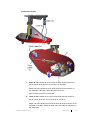
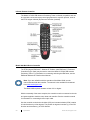
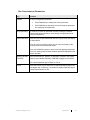
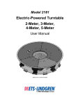
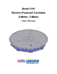
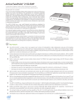
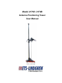
Model 2171B / 2170B Antenna Positioning Tower User Manual Model 2171B boresight ETS-Lindgren Inc. reserves the right to make changes to any products herein to improve functioning or design. Although the information in this document has been carefully reviewed and is believed to be reliable, ETS-Lindgren does not assume any liability arising out of the application or use of any product or circuit described herein; nor does it convey any license under its patent rights nor the rights of others. All trademarks are the property of their respective owners. © Copyright 2013–2015 by ETS-Lindgren Inc. All Rights Reserved. No part of this document may be copied by any means without written permission from ETS-Lindgren Inc. Trademarks used in this document: The ETS-Lindgren logo is a registered trademark, and EMCenter and EMControl are trademarks of ETS-Lindgren Inc. Revision Record MANUAL,2171B 2170B | Part #399364, Rev. D Revision ii Description Date A Initial Release December, 2013 B Updated Boom Load Limitations illustration March, 2014 C Updated Recommended Tools, Assembly Instructions, Air Polarization Operation; added Connecting Air Lines January, 2015 D Updated bore sight link configurations; updated drawings in back of manual June, 2015 www.ets-lindgren.com Table of Contents Notes, Cautions, and Warnings ....................................................................... vii 1.0 Introduction ................................................................................................... 9 ETS-Lindgren Patented Boresight System ......................................................................... 9 Boresight Function (2171B Only) ............................................................................... 10 Non-Boresight Function ............................................................................................. 10 Positioning Controller (Required) ..................................................................................... 11 Standard Configuration ..................................................................................................... 11 Tower Assembly......................................................................................................... 11 Variable Speed Motor ................................................................................................ 11 Links ........................................................................................................................... 11 Boresight with Centerline Pneumatic Polarization ..................................................... 11 Infrared (IR) Remote Controller ................................................................................. 11 Fiber Optic Control Cables ......................................................................................... 11 Fiber Optic Shield Room Penetration Kit ................................................................... 11 Optional Items................................................................................................................... 12 Offset Boom ............................................................................................................... 12 Additional Fiber Optic Cable ...................................................................................... 12 ETS-Lindgren Product Information Bulletin ...................................................................... 12 2.0 Maintenance ................................................................................................ 13 Air Cylinder Maintenance ................................................................................................. 13 Maintenance Schedule ..................................................................................................... 14 Every Three Months ................................................................................................... 14 Every Six Months ....................................................................................................... 14 Every Twelve Months ................................................................................................. 14 Replacement and Optional Parts ..................................................................................... 14 Service Procedures .......................................................................................................... 15 Contacting ETS-Lindgren ........................................................................................... 15 Sending a Component for Service ............................................................................. 15 Calibration Services and Annual Calibration ............................................................. 15 3.0 Specifications.............................................................................................. 17 Electrical Specifications .................................................................................................... 17 Physical Specifications ..................................................................................................... 17 4.0 Electrical Installation .................................................................................. 19 Wire Gauge....................................................................................................................... 19 www.ets-lindgren.com iii Power Cord ....................................................................................................................... 19 Connecting the Positioning Controller .............................................................................. 20 EMCenter RF Modular Platform ................................................................................. 20 Model 2090 Multi-Device Controller ........................................................................... 20 5.0 Assembly Instructions ............................................................................... 21 Included and Recommended Tools .................................................................................. 22 Included Tools ............................................................................................................ 22 Recommended Tools ................................................................................................. 22 Parts to Assemble ............................................................................................................ 22 Overview of Assembly Steps ............................................................................................ 23 Orientation of Parts during Assembly ............................................................................... 24 Mast Orientation ......................................................................................................... 24 Carrier Orientation ...................................................................................................... 24 Base Orientation ........................................................................................................ 25 Assembly Steps ................................................................................................................ 26 Step 1—Remove Carrier from Temporary Shipping Mast ......................................... 26 Step 2—Remove Temporary Shipping Mast from Base ............................................ 27 Step 3—Slide Carrier onto (Main) Mast ..................................................................... 28 Step 4—Begin Belt Installation .................................................................................. 29 Step 5—Insert Mast into Base ................................................................................... 32 Step 6—Connect Fiber Optic Cables ......................................................................... 33 Step 7—Adjust the Timing ......................................................................................... 35 Step 8—Finish Installing the Belt ............................................................................... 37 Step 9—Adjust Belt Tension ...................................................................................... 42 6.0 Additional Installation and Adjustments................................................... 43 Install Cable Antenna ....................................................................................................... 43 Attach Optional Offset Boom ............................................................................................ 44 Install Boresight Links and Level Carrier (2171B Only) ................................................... 46 Install Boresight Links ................................................................................................ 47 Level Carrier ............................................................................................................... 48 Install Non-Boresight Links and Level Carrier (2171B Only) ............................................ 49 Install Non-Boresight Links ........................................................................................ 49 Level Carrier ............................................................................................................... 49 7.0 Operation ..................................................................................................... 51 Pre-Operational Checklist ................................................................................................. 51 Air Polarization Operation ................................................................................................. 52 iv www.ets-lindgren.com Connecting Air Lines .................................................................................................. 53 Infrared Remote Controller ............................................................................................... 54 Model 2090 Multi-Device Controller ................................................................................. 54 Edit Configuration Parameters ................................................................................... 55 Tower Encoder Calibration ........................................................................................ 56 Start-Up ...................................................................................................................... 57 Shutdown ................................................................................................................... 57 Mounting Antennas ........................................................................................................... 57 Boom Load Limitations .............................................................................................. 58 Appendix A: Warranty ...................................................................................... 59 Appendix B: EC Declaration of Conformity .................................................... 61 Appendix C: Drawings ...................................................................................... 63 118100: Model 2171B Carrier Assembly (2 Pages) .................................................. 63 118200: Model 2171B Tower Assembly .................................................................... 63 118623: Model 2170B Carrier Assembly ................................................................... 63 118624: Model 2170B Tower Assembly .................................................................... 63 www.ets-lindgren.com v This page intentionally left blank. vi www.ets-lindgren.com Notes, Cautions, and Warnings Note: Denotes helpful information intended to provide tips for better use of the product. CAUTION: Denotes a hazard. Failure to follow instructions could result in minor personal injury and/or property damage. Included text gives proper procedures. WARNING: Denotes a hazard. Failure to follow instructions could result in SEVERE personal injury and/or property damage. Included text gives proper procedures. Note: See the ETS-Lindgren Product Information Bulletin for safety, regulatory, and other product marking information. www.ets-lindgren.com vii This page intentionally left blank. viii www.ets-lindgren.com 1.0 Introduction The ETS-Lindgren Model 2171B/2170B Antenna Positioning Tower meets ANSI C63.4 requirements for measurements above 1 GHz by keeping the antenna aimed at the equipment under test (EUT) while the antenna ascends and descends the mast. This is especially useful when high gain directional antennas are used. The Model 2171B easily adjusts for non-boresight testing and for 3-m, 5-m, and 10-m boresight testing. The Model 2171B/2170B is constructed as a single-piece mast of high density fiberglass-reinforced polymer square tubing. This material has a high degree of immunity from extended exposure to sunlight. The Model 2171B/2170B is also designed with a reduced base for easier maneuverability in smaller chambers. A toothed belt drive provides smooth ascent and descent of the carrier assembly. The belt is an industrial grade composite that was selected for strength and longevity. Model 2171B boresight (antenna not included) The Model 2171B/2170B features variable speed operation with speed rates that range from 3 cm/sec to 22 cm/sec, as controlled by an ETS-Lindgren positioning controller. For more information on the positioning controller, see page 11. The Model 2171B/2170B accepts stinger and other standard ETS-Lindgren antenna mounts. See Mounting Antennas on page 57 for more information. ETS-Lindgren Patented Boresight System The Model 2171B provides the ETS-Lindgren patented boresight system to provide direct antenna aim on EUT during scanning. This boresight meets the requirements of ANSI C63.4 2003 and 2009 for compliance with FCC measurements above 1 GHz. During scans, the boresight system maintains constant directional antenna positioning while varying the angle between the antenna and the mast. This is particularly important when using higher gain antennas of more than 3 dBi. As the antenna is raised above the ground, the tilt of the antenna will maintain the EUT within the half power (-3 dB) beamwidth. www.ets-lindgren.com Introduction 9 Note: The following drawings use a generic positioning tower to illustrate boresight and non-boresight function. BORESIGHT FUNCTION (2171B ONLY) NON-BORESIGHT FUNCTION 10 Introduction www.ets-lindgren.com Positioning Controller (Required) A positioning controller, such as the ETS-Lindgren EMCenter™ Modular RF Platform (with EMControl™ Positioner Controller Plug-In Card) or Model 2090 Multi-Device Controller, is required for operation, and is sold separately. Contact ETS-Lindgren for ordering information. Note: Existing ETS-Lindgren positioning controllers can be used with the Model 2171B/2170B; contact ETS-Lindgren to confirm your controller is installed with the required firmware. The Model 2090 requires firmware revision 3.21 or higher. Standard Configuration TOWER ASSEMBLY Single-piece mast, castered base, carrier assembly VARIABLE SPEED MOTOR LINKS Non-boresight and 3-, 5-, and 10-meter for boresight BORESIGHT WITH CENTERLINE PNEUMATIC POLARIZATION With adjustable rotational velocity INFRARED (IR) REMOTE CONTROLLER See page 51 FIBER OPTIC CONTROL CABLES 3- and 10-meter FIBER OPTIC SHIELD ROOM PENETRATION KIT www.ets-lindgren.com Routes the fiber optic control cable from the control room to the shield room while maintaining shielding attenuation. The pieces are made of brass for conductivity and provide attenuation of greater than 100 dB at 10 GHz. A single 25-mm (1.0-in) hole is required for mounting. Introduction 11 Optional Items OFFSET BOOM An optional offset boom is available (part# 118617). Contact ETS-Lindgren Sales Department for more information. ADDITIONAL FIBER OPTIC CABLE Various lengths of fiber optic cable are available by custom order. The standard length provided is 10 m (32.8 ft). ETS-Lindgren Product Information Bulletin See the ETS-Lindgren Product Information Bulletin included with your shipment for the following: 12 Warranty information Safety, regulatory, and other product marking information Steps to receive your shipment Steps to return a component for service ETS Lindgren calibration service ETS Lindgren contact information Introduction www.ets-lindgren.com 2.0 Maintenance CAUTION: Before performing any maintenance, follow the safety information in the ETS-Lindgren Product Information Bulletin included with your shipment. WARNING: Maintenance of Model 2171B/2170B is limited to the instructions provided here. If you have any questions concerning maintenance, contact ETS-Lindgren Customer Service. Do not make any modifications to this unit without consulting the factory directly. WARRANTY Only use replacement parts and fasteners ordered directly from the factory. This equipment should be operated and maintained by qualified personnel. Disconnect all air supply lines when servicing pneumatic components. Service equipment in accordance with the maintenance schedule provided. Periodically check belt for wear. Air Cylinder Maintenance The air cylinder uses a special O-ring lubricant: silicon grease designed specifically for O-rings. During maintenance apply this type of silicon grease to prevent excessive wear of the O-rings. www.ets-lindgren.com Maintenance 13 Maintenance Schedule Inspect belt for wear, tension, and cracking. Check all screws and bolts to confirm that are tight per assembly instructions. Inspect bolts and hardware for breakage. EVERY SIX MONTHS Check connecting control and all cables for degradation from environment and use. If necessary, replace per safety per local electrical codes. EVERY TWELVE MONTHS Use high-grade silicone grease on all carrier rollers. EVERY THREE MONTHS Replacement and Optional Parts Note: ETS-Lindgren may substitute a similar part or new part number with the same functionality for another part/part number. Contact ETS-Lindgren for questions about part numbers and ordering parts. Following are the part numbers for ordering replacement or optional parts for the Model 2171B/2170B. 14 Part Description Part Number Boresight links 3-meter link 5-meter links 10-meter links 119612 119613 (LH), 119665 (RH) 119614 (LH), 119666 (RH) Non-boresight link 1 1/2-in link 1-in link Cam knob Cam lock knob 118050 118051 118052 118059 Offset boom, 2171B/2170B 118617 Timing Belt (33 ft required) 880393 Fuse, 5 x 20mm 3A Slow 480029 Maintenance www.ets-lindgren.com Service Procedures CONTACTING ETS-LINDGREN Note: Please see www.ets-lindgren.com for a list of ETS-Lindgren offices, including phone and email contact information. SENDING A COMPONENT FOR SERVICE For the steps to return a system or system component to ETS-Lindgren for service, see the Product Information Bulletin included with your shipment. CALIBRATION SERVICES AND ANNUAL CALIBRATION See the Product Information Bulletin included with your shipment for information on ETS-Lindgren calibration services. www.ets-lindgren.com Maintenance 15 This page intentionally left blank. 16 Maintenance www.ets-lindgren.com 3.0 Specifications Electrical Specifications Voltage: 220 VAC Amp: 5.0 Line Frequency: 50/60 Hz Phase: Single Physical Specifications Polarization: 30° per second Scan Range: 1.0 m—4.0 m (39.37 in—157.48 in) Speed Range: 3 cm/sec to 22 cm/sec Cross-Boom Loading: 10.4 kg (23.0 lb) Separation Distance (boresight): 3 m, 5 m, 10 m Weight (approximate): 80 kg (175.0 lb) Maximum Overall Height: 2171B: 4.9 m (193 in) Base Dimensions (LxW): 1.2 m (47.5 in) x 0.8 m (34.0 in) www.ets-lindgren.com 2170B: 4.2 m (165 in) Specifications 17 This page intentionally left blank. 18 Specifications www.ets-lindgren.com 4.0 Electrical Installation CAUTION: Before connecting any components, follow the safety information in the ETS-Lindgren Product Information Bulletin included with your shipment. Electrical installation must be performed by a qualified electrician, and in accordance with local and national electrical standards. Make sure the power is off and secured before proceeding. Wire Gauge Whenever possible the motor should be powered from a separate branch circuit of adequate capacity to keep voltage drop to a minimum during startup and running. For longer runs, increase the wire size in accordance with the following wire selection guide. Note: Never use smaller than 14 AWG for any installation. Length of Wire @ 220 V: 0-15.24 m 15.24-30.48 m 30.48-60.96 m (0-50 ft) (50-100 ft) (100-200 ft) Wire Gauge Required: 14 AWG 14 AWG 14 AWG Power Cord The motor base is provided with an input AC power cord that is approximately 2.45 m (8 ft) long. This power cord is suitable for portable or indoor applications without modification. www.ets-lindgren.com Electrical Installation 19 Connecting the Positioning Controller EMCENTER RF MODULAR PLATFORM The ETS-Lindgren EMCenter™ Modular RF Platform (with EMControl™ Positioner Controller Plug-In Card) may be used to control the Model 2171B/2170B Antenna Positioning Tower. For information on connecting and using the EMCenter, see the EMCenter Modular RF Platform User Manual. MODEL 2090 MULTI-DEVICE CONTROLLER Any combination of primary devices (towers, turntables, reverberation paddles, MAPS, and so on) can be connected to the two device interface ports located on the rear panel of the Model 2090 Series Multi-Device Controller. For easy setup of an EMC facility, it is recommended that the Model 2171B/2170B Antenna Positioning Tower be connected to the Device 1 port. The default settings are for a tower connected to the Device 1 port and a turntable connected to the Device 2 port. Primary device connection is accomplished with a dual fiber optic cable included with the device. This cable terminates into two ST connectors that are identical at both ends. The cable is symmetrical, so either end can be connected to the Model 2090. A fiber optic cable connected to the IN port of a device should be connected to the primary OUT port of the motor base at the other end. Similarly, a fiber optic cable connected to the OUT port of the device should be connected to the primary IN port of the motor base at the other end. Older motor base designs have only one fiber optic connector pair, but the newer motor base interface provides a secondary interface reserved for future expansion. CAUTION: Fiber optic cabling for each device should not hang unsupported from the rear panel of the Model 2090. The fibers and connectors are easily broken if twisted or bent. Keep the fiber optic cables as straight as possible from the connector to the protective sheath. 20 Electrical Installation www.ets-lindgren.com 5.0 Assembly Instructions CAUTION: Before connecting any components, follow the safety information in the ETS-Lindgren Product Information Bulletin included with your shipment. This equipment should be installed, operated, and maintained by qualified personnel. Stay clear of all moving components on this equipment. Never stand beneath the carrier, whether moving or stationary. Note: You will require assistance from two or more team members to assemble the Model 2171B/2170B. Note: See the ETS-Lindgren Product Information Bulletin included with your shipment for information on unpacking and acceptance procedures. The Model 2171B/2170B Antenna Positioning Tower should be assembled in the location where it will be used. If movement to another location is required after assembly, partial disassembly will be required for it to fit through most doorways. www.ets-lindgren.com Assembly Instructions 21 Included and Recommended Tools INCLUDED TOOLS Part# 891780: Adjustable Wrench, 1-1/8” Jaw (quantity: 2). For all hex nuts. Part# 891781: Hex L-Key, 3/16” Hex (quantity: 1). For cam rollers on motor base. Part# 120927: Fiber Optic Connector Tool (quantity: 1). For fiber optic connection on mast. RECOMMENDED TOOLS Work bench or two sawhorses Medium-sized level Parts to Assemble These main parts are used to assemble the Model 2171B/2170B: Mast Carrier Belt Base Boresight shown; antenna not included Note: The Model 2171B/2170B ships with a small temporary shipping mast. The carrier is installed on this small mast and then inserted into the base for stability during transit. The temporary shipping mast should never be used for operation. 22 Assembly Instructions www.ets-lindgren.com Overview of Assembly Steps 1. Remove carrier from temporary shipping mast—see page 26. 2. Remove temporary shipping mast from base—see page 27. 3. Slide carrier onto (main) mast—see page 28. 4. Begin belt installation—see page 29. 5. Insert mast into base—see page 32. 6. Connect fiber optic cables—see page 33. 7. Adjust the timing—see page 35. 8. Finish installing the belt—see page 37. 9. Adjust belt tension—see page 42. www.ets-lindgren.com Assembly Instructions 23 Orientation of Parts during Assembly MAST ORIENTATION The fiber optic connectors are located on the front of the mast. CARRIER ORIENTATION 24 Assembly Instructions www.ets-lindgren.com BASE ORIENTATION www.ets-lindgren.com Assembly Instructions 25 Assembly Steps CAUTION: TAKE CARE TO AVOID DAMAGE TO FIBER OPTIC CABLES: Never pull, pinch, bend, twist, or place any kind of stress on the fiber optic cables. STEP 1—REMOVE CARRIER FROM TEMPORARY SHIPPING MAST With the base on the floor and the temporary shipping mast in a vertical position, carefully lift the carrier straight up, sliding it off of and away from the temporary shipping mast. 26 Assembly Instructions www.ets-lindgren.com STEP 2—REMOVE TEMPORARY SHIPPING MAST FROM BASE Note: Never use the temporary shipping mast for operation. In the following view the carrier and belt are shown, but only the mast is present during this step. Remove the two base studs by rotating and then pulling straight out. Lift up to remove the temporary shipping mast from the base. www.ets-lindgren.com Assembly Instructions 27 Note: Make sure to orient the carrier and mast as shown in Orientation During Assembly on page 24. STEP 3—SLIDE CARRIER ONTO (MAIN) MAST Place the mast horizontally onto an elevated, stable surface, such as across two sawhorses. Carefully slide the carrier onto the mast from the bottom of the mast. Orient the carrier so that when the mast is inserted into the base: 28 The air cylinder is on the same side of the mast as the fiber optic connectors; and When the mast is upright, the air cylinder will point downward. Assembly Instructions www.ets-lindgren.com STEP 4—BEGIN BELT INSTALLATION Remove the belt clamp plate by removing the four hex nuts. With the teeth facing inward, place one end of the belt in the notch, and then replace the belt clamp plate and hex nuts. Route the belt up the carrier, over the top of the mast, and then back down to the carrier. www.ets-lindgren.com Assembly Instructions 29 Route the belt to the top of the mast, over the pulleys, and down the other side of the mast. Remove the four hex nuts to remove the timing pulley plate. 30 Assembly Instructions www.ets-lindgren.com Thread the belt over the timing pulley. www.ets-lindgren.com Replace the plate and four hex nuts to keep the belt in place while you move the mast into a vertical position; you will remove the plate and hex nuts again to adjust the timing in step 7 on page 35. Assembly Instructions 31 Note: Make sure to orient the carrier and mast as shown in Orientation During Assembly on page 24. STEP 5—INSERT MAST INTO BASE Carefully move the mast and carrier into a vertical position and slide the mast into the base, aligning the fiber optic connectors on the front of the mast with access slot on the front of the base. Replace the two base studs removed in step 2 on page 27. Adjust the carrier height by moving the carrier past the lower limit switch until it stops at rest on the top of the base. 32 Assembly Instructions www.ets-lindgren.com CAUTION: TAKE CARE TO AVOID DAMAGE TO FIBER OPTIC CABLES: Never pull, pinch, bend, twist, or place any kind of stress on the fiber optic cables. STEP 6—CONNECT FIBER OPTIC CABLES Carefully plug the fiber optic cables through the access slot on the front of the base and into the fiber optic connectors located on the front of the mast. Two of the cables are marked U for the UPPER limit and two are marked L for the LOWER limit; plug the two cables marked U into the connectors marked U on the mast, and plug the two cables marked L into the connectors marked L. Either U cable can be plugged into either of the U connectors; either L cable can be plugged into either of the L connectors. When completely plugged in, the outer flange on the cable should be flush with the surface of the mast. Always use the flange on the cable to connect or disconnect the fiber optic cables; never pull or push the fiber optic cable using the collar or the cable. www.ets-lindgren.com Assembly Instructions 33 34 Assembly Instructions www.ets-lindgren.com STEP 7—ADJUST THE TIMING Remove the four hex nuts and the timing pulley plate. To adjust the timing between the boresight and the carrier: Manually rotate the timing pulley to move the cam link back toward the mast to the limit of its travel. www.ets-lindgren.com Assembly Instructions 35 36 Roll the pulley to engage the teeth and then pull the belt up, taking care to keep slack out of the lower section of belt between the motor base and the timing pulley. When done, replace the plate and four hex nuts. Assembly Instructions www.ets-lindgren.com STEP 8—FINISH INSTALLING THE BELT Four cam followers are located on the underside of the base next to motor base pulley. www.ets-lindgren.com Assembly Instructions 37 Reach under the base to access and remove the four cam followers with an Allen wrench. 38 Assembly Instructions View of two cam followers removed. www.ets-lindgren.com View of motor base pulley with cam followers removed. With teeth facing inward, continue routing the belt down, around the motor base pulley, and back up. www.ets-lindgren.com Replace the four cam followers and tighten with an Allen wrench. View of motor base pulley with threaded belt and re-installed cam followers. Assembly Instructions 39 Finish installing the belt by attaching it to the lower belt clamp. Remove the two hex nuts. 40 Assembly Instructions Remove small plate. www.ets-lindgren.com With the teeth facing inward, place the belt between the posts and in the lower belt clamp, and then all the slack out of the belt so that it is as taut as possible. www.ets-lindgren.com Replace the plate and two hex nuts. Assembly Instructions 41 STEP 9—ADJUST BELT TENSION Tighten nut located at top of upper belt clamp. Tension the belt until it is snug on the motor gear. Do not over-tension. CAUTION: To prevent excess belt from getting caught in the carrier during operation, roll up the excess belt and tie it to the carrier. 42 Assembly Instructions www.ets-lindgren.com 6.0 Additional Installation and Adjustments Install Cable Antenna 1. Feed the antenna cable into the curved elbow fitting, through the middle hose, and out the slotted end of the boom. 2. Attach the end of the cable to the antenna. 3. Insert the stinger into the boom and tighten boom knobs to secure the antenna in place. www.ets-lindgren.com Additional Installation and Adjustments 43 Attach Optional Offset Boom Note: The Model 2171B/2170B ships with a stinger-mount boom. If you ordered an optional offset boom (part# 118617), follow these steps to remove the stinger-mount boom and install the offset boom. 1. Rotate the two boom knobs to completely remove them. 2. Remove the stinger-mount and two clamps by sliding them off the boom. 44 Additional Installation and Adjustments www.ets-lindgren.com 3. Insert the offset boom into the end of the Model 2171B/2170B boom. 4. Tighten the three knobs on the offset boom to secure into place. www.ets-lindgren.com Additional Installation and Adjustments 45 Install Boresight Links and Level Carrier (2171B Only) CAUTION: Install only one set of boresight links at a time. Never operate the Model 2171B with boresight and non-boresight links installed at the same time. Note: The 3m uses one link; the 5m and the 10m use a set of two links (left and right). For part number information, see Replacement and Optional Parts on page 14. Note: Make sure to install the 5m and 10m links in the correct location. For orientation, face the Model 2171B with the curved elbow fitting extending to the right. The left link is installed on the left side of the carrier, which is the closer side of the carrier; the right link is installed on the right side, which is the far side. 46 Additional Installation and Adjustments www.ets-lindgren.com INSTALL BORESIGHT LINKS Each boresight link is marked with a pattern of holes that identifies the type of testing it is used to perform. 3m link: 3 holes 5m links: 5 holes 10m links: 10 holes The carrier is marked with a corresponding pattern of holes indicating the correct installation location for each. To install a boresight link, match the hole pattern on the link with the hole pattern on the carrier, remove the cam pin, bushings, and knobs, install the link, and then replace pin, bushings, and knobs. To install a set of links, make sure to install the left link on the left side of the carrier and the right link on the right side; see page 46 for more information. www.ets-lindgren.com The hole patterns on the carrier match the hole patterns on the links Additional Installation and Adjustments 47 LEVEL CARRIER Place a level gauge on the carrier boom, rotate the cam pin knob until the carrier is level, and then re-tighten the knob. Do not overtighten. 48 Additional Installation and Adjustments www.ets-lindgren.com Install Non-Boresight Links and Level Carrier (2171B Only) CAUTION: Never operate the Model 2171B with boresight and non-boresight links installed at the same time. INSTALL NON-BORESIGHT LINKS If installed, remove boresight links. Install non-boresight links in the non-boresight locations on the carrier. To adjust the horizontal level up or down, loosen the inner middle knob and then rotate the outer middle knob. Retighten inner knob to set LEVEL CARRIER Place a level gauge on the mounting section of the carrier. Tighten all knobs on the non-boresight links. Do not overtighten. www.ets-lindgren.com Additional Installation and Adjustments 49 This page intentionally left blank. 50 Additional Installation and Adjustments www.ets-lindgren.com 7.0 Operation CAUTION: Before placing into operation, follow the safety information in the ETS-Lindgren Product Information Bulletin included with your shipment. This equipment should be installed, operated, and maintained by qualified personnel. Stay clear of all moving components on this equipment. Never stand beneath the carrier, whether moving or stationary. Note: The stationary cam link assembly should never be attached to the carrier when using the boresight. Pre-Operational Checklist □ Verify that the power lines are connected for the tower, controller, and any other equipment to be used for testing. □ Verify the fiber optic cables are connected. □ Verify the antenna connected to the boom is securely mounted. □ Connect the feed cable to the antenna. □ Before moving the carrier on the mast up or down, verify there are no people standing near the boom. www.ets-lindgren.com Operation 51 Air Polarization Operation CAUTION: Prior to using air polarization, make sure that when the antenna polarizes that it turns freely, avoiding contact with anything (the base, the floor, and so on). The flow limit controls located on the air cylinder are set at the factory. Use the flow limit controls to change the speed. If polarization is operating at an excessive speed, the antenna mounted to the boom could incur damage. The automated air polarization assembly includes variable speed polarization cycling using flow limit controls. The air cylinder is made of non-conductive material and will polarize the largest antenna recommended for the tower. The polarization speed range is 3 degrees to 30 degrees per second. A regulated air supply of 4.0 bar to 5.5 bar (60 psi to 80 psi) is needed for this feature. It is important to have clean and dry air; so we recommend the use of a 40 micron filter in close proximity to the motor base. Ten meters of UV stabilized air hose is included as well as a 1/8 inch NPT fitting. A metric fitting for a 4 mm tube may be supplied by the customer. 52 Operation www.ets-lindgren.com CONNECTING AIR LINES 1. Upper air line—Attach an air hose from the upper flow limit control on the air cylinder to the right air line connector on the base. Attach one end of another air hose to the upper air hose connector on the underside of the base. Attach the other end to the upper air hose barb on the motor base. 2. Lower air line—Attach an air hose from the lower flow limit control on the air cylinder to the left air line connector on the base. Attach one end of another air hose to the lower air hose connector on the underside of the base. Attach the other end to the lower air hose barb on the motor base. www.ets-lindgren.com Operation 53 Infrared Remote Controller The Model 2171B/2170B Antenna Positioning Tower is infrared compatible, and can be used with a universal remote control programmed to a specific protocol, such as the ETS-Lindgren Infrared (IR) Remote Controller (included). Model 2090 Multi-Device Controller The ETS-Lindgren EMCenter™ Modular RF Platform (with EMControl™ Positioner Controller Plug-In Card) may be used to control the Model 2171B/2170B Antenna Positioning Tower. For information on connecting and using the EMCenter, see the EMCenter Modular RF Platform User Manual. Note: If you are unfamiliar with the operation of the Model 2090, see the manual included with the controller. The manual is also available for download from www.ets-lindgren.com. The Model 2090 requires firmware revision 3.21 or higher.. With the assembly of the tower complete, the controller must be connected to the unit and power applied to both the motor base and controller. See the controller manual for information on connecting the fiber optic cable. Use the controller to check the clockwise (CW) and counterclockwise (CCW) rotation in both directions by a few degrees. The position in degrees increases (+) in the CW direction and decreases (-) in CCW direction. 54 Operation www.ets-lindgren.com EDIT CONFIGURATION PARAMETERS Key Function PARAM To edit a configuration parameter: Press PARAM key to display the current parameter. Press PARAM key repeatedly to scroll through the parameter list, displaying each parameter. STEP (INC/DEC) To scroll up or down the parameter list while viewing a parameter. Reduces the effort necessary to scan through a long parameter list using the PARAM key. LIMIT/POSITION Press any of the LIMIT/POSITION selection keys to return the display to that selection. Press any of the remaining motion keys to return the display to the current position and execute that motion. Press the PARAM key again to return to the last displayed parameter in the list, allowing easy transition between parameter adjustment and device operation. INCRM, DECRM, or ENTER Once the desired limit, position, or parameter is visible in the display window, press INCRM, DECRM, or ENTER to toggle into edit mode. The lowest adjustable digit will flash on and off. LOCAL Press the LOCAL key for that device to switch the flashing digit to the next higher digit. In this way, it is possible to rapidly adjust any digit of a multi-digit parameter or limit. www.ets-lindgren.com Operation 55 TOWER ENCODER CALIBRATION Note: Parameter C must be set to 2000 for the Model 2171B/2170B. Parameter C, the encoder calibration parameter, is the setting that converts the encoder count values returned from a motor base into the corresponding centimeter or degree position reading. For towers, this represents the number of encoder counts per meter. This parameter allows a variety of standard, retrofit, and custom devices to be used. If the given value does not work correctly, the encoder calibration value can be determined using the following procedure: 1. Set the encoder calibration value to 1000. 2. Make sure the tower is positioned to allow at least one meter of travel in the upward direction at an easily measurable height, and then set the current position reading to 000.0. To allow this, you must adjust the lower limit setting. 3. Use the STEP keys to adjust the height of the carrier until it is one meter above the start point. 4. Record the reading of the display, ignoring the decimal point. For example, 200.0 would be 2000. This is the encoder calibration value. Note: If the value is below 1000, the resolution of the encoder is low and the Model 2090 will not provide 0.1-cm resolution, even though the display shows that digit. If the value is past 9999, the encoder has too many counts per meter and the controller cannot correct for it. In this case, contact ETS-Lindgren for assistance. 5. Enter the encoder calibration value and reset the limits and position information. 6. Test the tower by moving it a known distance and comparing the display to the measured distance traveled. It may be necessary to adjust the encoder calibration value up or down slightly depending on the result. 56 Operation www.ets-lindgren.com START-UP After completing the pre-operational checks, turn on the Model 2090 by pressing the power button. SHUTDOWN Move the carrier to an accessible height to remove the antenna and confirm the unit has come to a complete stop. Press the power button on the Model 2090 to turn it off. Mounting Antennas The Model 2171B/2170B accepts antennas with the following mount types: Stinger-mount boom: Stinger-mount Optional offset boom: 7/8–14 thread, 1/4–20 thread These mount types will maintain the centerline axis during polarization. The antenna should be mounted on the boom as close to the carrier as possible. Insert the mounting knobs through the holes on the boom and align the mounting holes on the antenna with the threaded end of the mounting knobs. Secure the antenna in place by tightening the threaded knobs into the receptacle mounting holes on the antenna. www.ets-lindgren.com Operation 57 BOOM LOAD LIMITATIONS Note: Boom loading at 25 ft lb (33.9 Nm) measured along the boom from the mast. 58 Operation www.ets-lindgren.com Appendix A: Warranty Note: See the Product Information Bulletin included with your shipment for the complete ETS-Lindgren warranty for your Model 2171B/2170B Antenna Positioning Tower. DURATION OF WARRANTIES FOR MODEL 2171B/2170B All product warranties, except the warranty of title, and all remedies for warranty failures are limited to two years. Product Warranted Duration of Warranty Period Model 2171B/2170B Antenna Positioning Tower 2 Years www.ets-lindgren.com Warranty 59 This page intentionally left blank. 60 Warranty www.ets-lindgren.com Appendix B: EC Declaration of Conformity www.ets-lindgren.com EC Declaration of Conformity 61 This page intentionally left blank. 62 EC Declaration of Conformity www.ets-lindgren.com Appendix C: Drawings The following drawings are located in the pocket of the back cover of the manual: 118100: Model 2171B Carrier Assembly (2 Pages) page 1: Boresight Option shown page 2: Non-Boresight Option shown 118200: Model 2171B Tower Assembly (2 pages) page 1-2: Boresight Option shown 118623: Model 2170B Carrier Assembly 118624: Model 2170B Tower Assembly www.ets-lindgren.com Drawings 63 REF DRAWING REVISIONS 27 44 NOTE: -BORESIGHT OPTION SHOWN ECN 37 42 H 8 26 78 79 7 79 51 3 76 77 10 64 79 80 79 78 77 76 75 74 73 72 71 70 69 68 67 66 65 64 63 62 61 60 59 58 57 56 55 54 53 52 51 50 49 48 47 46 45 44 43 42 41 40 39 38 37 36 35 34 33 32 31 30 29 28 27 26 25 24 23 22 21 20 19 18 17 16 15 14 13 12 11 10 9 8 7 6 5 4 3 2 1 79 62 2 37 70 75 35 75 69 4 14 1 72 65 79 80 22 67 19 61 29 25 35 43 53 32 79 28 80 9 41 12 66 A APPROVED ADDED 5M AND 10M LINKS 06/03/14 JSW 33 7 2 DATE DESCRIPTION 36 34 A REV 28 30 3M, 5M AND 10M LINK SETS (ATTACH 3M LINKS FOR SHIPPMENT) 24 50 20 63 79 45 46 48 47 23 34 59 58 ITEM# 910827 910826 891539 891538 891537 891535 891533 891531 880459 880458 120747 120746 120252 119962 119961 119960 119959 119957 119956 119937 119934 119933 119932 119666 119665 119614 119613 119612 119558 118632 118519 118518 118494 118493 118492 118491 118147 118144 118142 118092 118091 118085 118084 118083 118081 118078 118076 118073 118071 118070 118069 118068 118066 118065 118064 118063 118062 118061 118060 118059 118058 118057 118052 118051 118050 118049 118048 118047 118046 118045 118044 118020 118018 118017 118016 118015 113493 109572 109034 108990 PART NUMBER NUT,1/2-13,HEX,FG,BROWN NUT,3/8-16,HEX,FG,BROWN HOSE,1-1/4" VACUUM BARB,HOSE,1-1/4" NPT MALE ADAPTER,1-1/4" NPT FEMALE COUPLING,GRAY,1-1/4" PVC SNAP RING,30MM SHAFT STUD,1"-8 X 12,NYLATRON GS BEARING,3/8 ID X 7/8 OD BEARING,30MM ID X 37MM OD CONDUIT,1-1/4" GRAY PVC ELBOW,GRAY,1-1/4" PVC,SLOT PLATE,BELT CLAMP,W/ STUD STUD,1/2-13 X 4.50,FG STUD,1/2-13 X 8.13,FG STUD,3/8-16 X 2.13,FG STUD,3/8-16 X 8.38,FG STUD,3/8-16 X 6.50,FG STUD,3/8-16 X 7.25,FG KNOB,GLUED,CAM,2171B BUSHING,SLIDER,ACTUATOR ECCENTRIC,CAM,STYLE 3,2171B KNOB,CAM,2171B LINK,CAM 10M,STYLE 3,RH,2171B LINK,CAM 5M,STYLE 3,RH,2171B LINK,10M,2171B LINK,5M,2171B LINK,CAM 3M,STYLE 3,2171B DOWEL,3/8 X 1.90,G10 STUD,3/8-16 X 10.25,FG ROLLER,MAST,2171B CLAMP,BELT,2171B DOWEL,3/8 X 3.45,G10 STANDOFF,3/8 X 2-1/2,G10 BRKT.,ROLLER,2171B ROLLER,CARRIER,2171B STUD,1/2-13 X 9.5,FG STUD,3/8-16 X 4.50,FG STUD,3/8-16 X 13.87,FG SPROCKET ASSY.,B/S SPACER,THRUST,B/S PLATE,BODY,CLAMP BODY,CLAMP,BELT NUT,TENSION,BELT BLOCK,BELT CLAMP PIPE,CUT,1.25 X 6.87,GRAY PVC ACTUATOR,118076 BLOCK,COAX SUPPORT PILLOW BLOCK,LONG,B/S DOWEL, 1/8 X .95 G10 IDLER,B/S DOWEL,3/8 X 2.50,G10 BRACKET,IDLER,B/S NUT,RACK,POLAR GEAR,POLAR,2171B CYLINDER,POLAR,2171B PLATE,MAST,OUTER PLATE,MAST,INNER BLOCK,SUPPORT,MAST PLATES KNOB,GLUED,CAM LOCK DOWEL, 3/16 X 1.45 G10 KNOB,GLUED,1/2" LINK CAM KNOB,NB LINK,NB,1" LINK,NB,1-1/2" DOWEL,3/8 X .63,G10 ANCHOR,POLAR RACK,MACHINED,POLAR BOOM,POLAR,2171B CAM,CYLINDER,2171B CAM,BORESITE,2171B BLOCK, MAIN BEARING BEARING, POLAR BOOM BLOCK,BEARING,2171B POLAR BUSHING, PIVOT BUSHING #2, PIVOT ASSY,BUSHING,6.0" STINGER STUD,3/8-16 X 7.50,FG KNOB,1/2-13 X 1.1,GLUED CLAMP,STINGER 4 40 1.5 1 1 2 2 1 6 4 1 1 1 1 1 2 4 4 2 1 2 1 1 1 1 1 1 2 1 2 8 1 2 4 4 2 1 4 1 1 2 1 1 1 1 2 1 1 2 3 2 2 2 1 1 1 1 1 1 1 8 2 1 1 1 4 2 1 1 1 1 2 3 3 1 2 1 2 2 2 118100 /QTY. DESCRIPTION THIRD ANGLE PROJECTION ETS LINDGREN TM An ESCO Technologies Company UNLESS OTHERWISE SPECIFIED: INITIAL DIMENSIONS ARE IN INCHES REMOVE ALL BURRS AND SHARP EDGES SURFACE FINISH 63 RMS OR BETTER DRAFTING TOLERANCES ARE: DECIMALS ANGLES ± X.XX .015 ± .5 X.XXX ± .005 ENGINEERING FINISH JAD SRK NONE DATE TITLE CARRIER,B/S,2171B 04-19-12 04/2012 PROPRIETARY INFORMATION ANY DUPLICATION OF THIS DOCUMENT, WHOLE OR IN PART, WITHOUT EXPRESS WRITTEN PERMISSION OF ETS LINDGREN IS PROHIBITED. SIZE D SCALE 1:4 DWG. NO. DO NOT SCALE DRAWING REV. 118100 SHEET 1 H OF 2 REF DRAWING NOTE: -NON-BORESIGHT OPTION SHOWN NOTE: THESE PARTS NOT ATTACHED FOR SHIPMENT 16 8 49 17 19 18 19 21 11 C 31 C 13 D 73 29 D 42 38 19 5 32 23 68 6 79 39 VIEW A-A SECTION C-C 74 32 40 71 40 74 72 52 SECTION D-D PROPRIETARY INFORMATION ANY DUPLICATION OF THIS DOCUMENT, WHOLE OR IN PART, WITHOUT EXPRESS WRITTEN PERMISSION OF ETS LINDGREN IS PROHIBITED. SIZE D SCALE 1:4 DWG. NO. DO NOT SCALE DRAWING REV. 118100 SHEET 2 H OF 2 REF DRAWING REVISIONS ECN NOTE: -BORESIGHT OPTION SHOWN -NON-BORESIGHT OPTION NOT SHOWN -SEE 118100 FOR DETAILS REV F 13 DATE APPROVED 09/26/14 JRC DESCRIPTION CHNG FIBER OPTICS 35 12 11 880393 3 4884 192.30 LUBE LEAD SCREW (INTERNAL) WITH 890943 48 15 LABEL CABLES "U" FOR UPPER LIMIT AND "L" FOR LOWER LIMIT. 6 25 24 PLUG FOR 505034 CONNECTORS 1 5 NUT,M6,HEX,SS,NYLOK NUT,M6,HEX,SS BOLT,M6 X 35,HEX,SS SCREW,M6 X 35,PHIL,PAN,SS SCREW,M6 X 30,PHIL,PAN,SS SCREW,M3 X 12MM,PHIL,FLAT,SS LABEL,PINCH POINT,INTL SYMBOL LABEL,HAND CRUSH,INTL SYMBOL LABEL,2171B LOGO 14 8 6 4 12 4 1 1 1 37 36 35 34 33 32 911204 910899 910686 910455 905194 905093 BOLT,5/8-11 X 4.5",HEX,GF NYLON,BLACK NUT,5/8-11,FG,BROWN SCREW,10-32 X 1/2,PHIL,FLAT,SS WASHER,1/4,FLAT,SS COUPLING,BULKHEAD,1/8 NPT FLOW CONTROL,RT ANG,1/8 NPT 3 6 4 24 2 2 30 29 28 890950 890949 890948 25 24 890465 890464 22 860140 16 15 14 13 12 11 10 9 8 7 6 5 4 3 2 1 ITEM NO. 120161 120067 119970 118181 118179 118178 118177 118176 118175 118174 118173 118172 118171 118100 109282 109250 42 14 8 EPOXY TO BASE 38 16 36 37 7 EPOXY TO BASE 9 48 36 2 7 31 47 34 27 26 7 864 34.00 28 EPOXY TO BASE 23 MAST HIDDEN FOR CLARITY 43 30 33 21 20 19 18 17 22 10 44 46 4 1207 47.50 36 2 THIRD ANGLE PROJECTION 920001 EPOXY KIT 2-PART RESIN T-88 SLEEVING,SLIT-CONVOLUTED,PE,1/4" ID 20 890947 890943 HOSE,TWIN 1/8 ID X 1/4 OD,COILED,20 FT GREASE,SILICONE,O-RING LUBE 1 .1 880393 BELT,TIMING,T10,25MM,ESD 33 33 2 2 4 4 1 FITTING,TUBE,1/8 NPT TO .17 ID,RT ANGLE CASTER,3" RIGID,250 LB CASTER,3" SWIVEL W/BRAKE,250 LB 2 2 1 BARB HOSE 11924-1 CLIPPARD NUT TUBE 5000-2 CLIPPARD 4 4 NYLON TUBING,.250 OD X .170 ID,BLACK 708093 708092 708091 505034 121162 FIBER OPTIC CABLE LIMIT SWITCH 0.5M FIBER OPTIC CABLE LIMIT SWITCH 4.75M FIBER OPTIC CABLE 1M POF - POF SIMPLEX CONNECTOR HFBR-4501 HEWLETT PACK 2171B SHIPPING MAST MAST BOLT,GLUED FIBER OPTIC PLUG PLATE,MAST,2171B FIBER OPTIC PLUG,MAST,2171B ASSY.,PULLEY BLOCK,2171B SWITCH,LIMIT,F.O.,.25 WT MAST,2171B PROTECTOR,F.O. AND AIR,2171B GUSSET,REAR,2171B GUSSET,FORWARD,2171B NUT,GUSSET,2171B TUBE,BRACE,2171B BRACE,FORWARD,2171B BASE,2171B CARRIER,B/S,2171B STUD,5/8-11 X 4.00,FG LOCK,MOLDED,F.O. CABLE DESCRIPTION PART NUMBER ETS LINDGREN 2 1 1 1 2 1 1 1 1 5 1 2 1 1 3 4 118200/QTY. TM An ESCO Technologies Company UNLESS OTHERWISE SPECIFIED: 45 34 .1 890983 29 43 1 930688 930681 930665 930663 930662 930341 920825 920824 920820 16 120067 EPOXY TO MAST ASSY,2171B MOTORBASE 47 46 45 44 43 42 41 40 39 24 25 32 F.O. CABLES EXIT HERE. ATTACH CONVOLUTED TUBE W/BLACK TIE WRAPS AND ROUTE THROUGH MAST TO LIMITS.(708091) 118166 INITIAL DIMENSIONS ARE IN INCHES REMOVE ALL BURRS AND SHARP EDGES SURFACE FINISH 63 RMS OR BETTER DRAFTING TOLERANCES ARE: DECIMALS ANGLES ± X.XX .015 ± .5 X.XXX ± .005 ENGINEERING FINISH JAD SRK NONE DATE TITLE TOWER ASSY,2171B 04-24-12 PROPRIETARY INFORMATION ANY DUPLICATION OF THIS DOCUMENT, WHOLE OR IN PART, WITHOUT EXPRESS WRITTEN PERMISSION OF ETS LINDGREN IS PROHIBITED. SIZE D SCALE 1:7 DWG. NO. DO NOT SCALE DRAWING REV. 118200 SHEET 1 F OF 2 REF DRAWING REFERENCE FOR SHIPPING ONLY NOTE: DO NOT ATTACHED NON-BORESIGHT LINKS FOR SHIPMENT INSTALL 120162 FOR SHIPMENT (SHIPPING ONLY) ETS LINDGREN THIRD ANGLE PROJECTION TM An ESCO Technologies Company UNLESS OTHERWISE SPECIFIED: INITIAL DIMENSIONS ARE IN INCHES REMOVE ALL BURRS AND SHARP EDGES SURFACE FINISH 63 RMS OR BETTER DRAFTING TOLERANCES ARE: DECIMALS ANGLES ± X.XX .015 ± .5 X.XXX ± .005 ENGINEERING FINISH JAD SRK NONE DATE TITLE TOWER ASSY,2171B 04-24-12 PROPRIETARY INFORMATION ANY DUPLICATION OF THIS DOCUMENT, WHOLE OR IN PART, WITHOUT EXPRESS WRITTEN PERMISSION OF ETS LINDGREN IS PROHIBITED. SIZE D SCALE 1:7 DWG. NO. DO NOT SCALE DRAWING REV. 118200 SHEET 2 E OF 2 REF DRAWING REVISIONS ECN REV A 57 48 11 37 27 13 23 19 DATE APPROVED 12/09/13 JRC DESCRIPTION ADDED 120252 18 12 2 4 1 7 26 10 24 58 51 3 57 48 57 56 21 57 46 19 55 54 45 57 30 52 53 48 57 35 32 20 44 57 49 43 8 16 ? 31 17 29 51 58 28 33 36 57 57 36 57 25 47 57 44 20 34 38 59 9 40 39 42 41 14 22 5 THIRD ANGLE PROJECTION 59 120252 58 910827 57 910826 56 891539 55 891538 54 891537 53 891536 52 891535 51 119962 50 119961 49 119960 48 119959 47 119957 46 119956 45 118632 44 118519 43 118518 42 118494 41 118493 40 118492 39 118491 38 118284 37 118147 36 118144 35 118142 34 118085 33 118084 32 118083 31 118081 30 118078 29 118073 28 118070 27 118065 26 118064 25 118063 24 118062 23 118061 22 118060 21 118059 20 118058 19 118057 18 118052 17 118051 16 118050 15 118049 14 118048 13 118047 12 118046 11 118045 10 118044 9 118020 8 118018 7 118017 6 118016 5 118015 4 113493 3 109572 2 109034 1 108990 ITEM PART NO. NUMBER PLATE,BELT CLAMP,W/ STUD NUT,1/2-13,HEX,FG,BROWN NUT,3/8-16,HEX,FG,BROWN HOSE,1-1/4" VACUUM BARB,HOSE,1-1/4" NPT MALE ADAPTER,1-1/4" NPT FEMALE ELBOW,GRAY,1-1/4" PVC COUPLING,GRAY,1-1/4" PVC STUD,1/2-13 X 4.50,FG STUD,1/2-13 X 8.13,FG STUD,3/8-16 X 2.13,FG STUD,3/8-16 X 8.38,FG STUD,3/8-16 X 6.50,FG STUD,3/8-16 X 7.25,FG STUD,3/8-16 X 10.25,FG ROLLER,MAST,2171B CLAMP,BELT,2171B DOWEL,3/8 X 3.45,G10 STANDOFF,3/8 X 2-1/2,G10 BRKT.,ROLLER,2171B ROLLER,CARRIER,2171B PLATE,CARRIER,2171,NON-BS STUD,1/2-13 X 9.5,FG STUD,3/8-16 X 4.50,FG STUD,3/8-16 X 13.87,FG PLATE,BODY,CLAMP BODY,CLAMP,BELT NUT,TENSION,BELT BLOCK,BELT CLAMP PIPE,CUT,1.25 X 6.87,GRAY PVC BLOCK,COAX SUPPORT DOWEL, 1/8 X .95 G10 NUT,RACK,POLAR GEAR,POLAR,2171B CYLINDER,POLAR,2171B PLATE,MAST,OUTER PLATE,MAST,INNER BLOCK,SUPPORT,MAST PLATES KNOB,GLUED,CAM LOCK DOWEL, 3/16 X 1.45 G10 KNOB,GLUED,1/2" LINK CAM KNOB,NB LINK,NB,1" LINK,NB,1-1/2" DOWEL,3/8 X .63,G10 ANCHOR,POLAR RACK,MACHINED,POLAR BOOM,POLAR,2171B CAM,CYLINDER,2171B CAM,BORESITE,2171B BLOCK, MAIN BEARING BEARING, POLAR BOOM BLOCK,BEARING,2171B POLAR BUSHING, PIVOT BUSHING #2, PIVOT ASSY,BUSHING,6.0" STINGER STUD,3/8-16 X 7.50,FG KNOB,1/2-13 X 1.1,GLUED CLAMP,STINGER DESCRIPTION ETS LINDGREN 1 4 40 1 1 1 1 1 1 1 2 4 4 2 2 8 1 2 4 4 2 2 1 4 1 1 1 1 1 1 1 3 1 1 1 1 1 1 1 8 2 1 1 1 4 2 1 1 1 1 2 3 3 1 2 1 2 2 2 QTY TM An ESCO Technologies Company 6 58 50 5 UNLESS OTHERWISE SPECIFIED: INITIAL DIMENSIONS ARE IN INCHES REMOVE ALL BURRS AND SHARP EDGES SURFACE FINISH 63 RMS OR BETTER DRAFTING TOLERANCES ARE: DECIMALS ANGLES ± X.XX .015 ± .5 X.XXX ± .005 ENGINEERING FINISH JAD SRK NONE DATE TITLE CARRIER2170B 04-19-12 09/12/12 PROPRIETARY INFORMATION ANY DUPLICATION OF THIS DOCUMENT, WHOLE OR IN PART, WITHOUT EXPRESS WRITTEN PERMISSION OF ETS LINDGREN IS PROHIBITED. SIZE D SCALE 1:4 DWG. NO. DO NOT SCALE DRAWING REV. 118623 SHEET 1 A OF 1 REF DRAWING REVISIONS ECN 12 REV A DATE APPROVED 12/09/13 JRC DESCRIPTION REPLACED 118625 WITH 120265 11 28 14 33 27 37 DETAIL A SCALE 1 : 4 23 26 20 37 930688 36 930681 35 930665 34 930663 33 930662 32 930341 31 920001 30 911204 29 910899 28 910686 27 910455 26 905194 25 905093 24 890950 23 890949 22 890948 21 890465 20 890464 19 880393 18 860140 17 120161 16 120067 15 119970 14 120265 13 118623 12 118181 11 118179 10 118177 9 118176 8 118175 7 118174 6 118173 5 118172 4 118171 3 118166 2 109282 1 109250 ITEM PART NO. NUMBER 13 DETAIL B SCALE 1 : 4 5 5 25 20 21 6 30 8 17 EPOXY 29 4 4 24 26 18 5 9 EPOXY A 3 B 29 2 35 37 27 27 7 22 10 34 36 ETS LINDGREN THIRD ANGLE PROJECTION 4 14 8 6 4 12 4 .02 3 6 4 24 2 2 2 2 1 4 4 33 33 2 1 1 1 1 1 2 1 1 1 5 1 2 1 1 3 4 QTY TM An ESCO Technologies Company UNLESS OTHERWISE SPECIFIED: 23 NUT,M6,HEX,SS,NYLOK NUT,M6,HEX,SS BOLT,M6 X 35,HEX,SS SCREW,M6 X 35,PHIL,PAN,SS SCREW,M6 X 30,PHIL,PAN,SS SCREW,M3 X 12MM,PHIL,FLAT,SS EPOXY,2-PART T88 BOLT,5/8-11 X 4.5",HEX,GF NYLON,BLACK NUT,5/8-11,FG,BROWN SCREW,10-32 X 1/2,PHIL,FLAT,SS WASHER,1/4,FLAT,SS COUPLING,BULKHEAD,1/8 NPT FLOW CONTROL,RT ANG,1/8 NPT FITTING,TUBE,1/8 NPT TO .17 ID,RT ANGLE CASTER,3" RIGID,250 LB CASTER,3" SWIVEL W/BRAKE,250 LB BARB HOSE 11924-1 CLIPPARD NUT TUBE 5000-2 CLIPPARD BELT,TIMING,T10,25MM,ESD NYLON TUBING,.250 OD X .170 ID,BLACK MAST BOLT,GLUED FIBER OPTIC PLUG PLATE,MAST,2171B FIBER OPTIC PLUG,MAST,2171B MAST,2170B CARRIER2170B ASSY.,PULLEY BLOCK,2171B SWITCH,LIMIT,F.O.,.25 WT PROTECTOR,F.O. AND AIR,2171B GUSSET,REAR,2171B GUSSET,FORWARD,2171B NUT,GUSSET,2171B TUBE,BRACE,2171B BRACE,FORWARD,2171B BASE,2171B MOTORBASE,2171 STUD,5/8-11 X 4.00,FG LOCK,MOLDED,F.O. CABLE DESCRIPTION INITIAL DIMENSIONS ARE IN INCHES REMOVE ALL BURRS AND SHARP EDGES SURFACE FINISH 63 RMS OR BETTER DRAFTING TOLERANCES ARE: DECIMALS ANGLES ± X.XX .015 ± .5 X.XXX ± .005 ENGINEERING FINISH SRK NONE DATE TITLE TOWER ASSY,2170B 09/12/12 PROPRIETARY INFORMATION ANY DUPLICATION OF THIS DOCUMENT, WHOLE OR IN PART, WITHOUT EXPRESS WRITTEN PERMISSION OF ETS LINDGREN IS PROHIBITED. SIZE D SCALE 1:12 DWG. NO. DO NOT SCALE DRAWING REV. 118624 SHEET 1 A OF 1