1
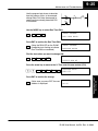
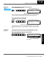
9–18
Maintenance and Troubleshooting
Machine Startup and Program Troubleshooting
Maintenance
and Troubleshooting
The DL205 CPUs provide several features to help you debug your program before
and during machine startup. This section discusses the following topics which can
be very helpful.
Syntax Check
S
Program Syntax Check
S
Duplicate Reference Check
S
Test Modes
S
Special Instructions
S
Run Time Edits
S
Forcing I/O Points
Even though the Handheld Programmer and DirectSOFT32 provide error checking
during program entry, you may want to check a modified program. Both
programming devices offer a way to check the program syntax. For example, you
can use AUX 21, CHECK PROGRAM to check the program syntax from a Handheld
Programmer, or you can use the PLC Diagnostics menu option within
DirectSOFT32. This check will find a wide variety of programming errors. The
following example shows how to use the syntax check with a Handheld Programmer.
Use AUX 21 to perform syntax check
CLR
C
B
2
1
AUX
ENT
AUX 21 CHECK PRO
1:SYN 2:DUP REF
Maintenance
and Troubleshooting
Select syntax check (default selection)
ENT
(You may not get the busy display
if the program is not very long.)
BUSY
One of two displays will appear
Error Display (example)
$00050 E401
MISSING END
(shows location in question)
Syntax OK display
NO SYNTAX ERROR
?
See the Error Codes Section for a complete listing of programming error codes. If
you get an error, press CLR and the Handheld will display the instruction where the
error occurred. Correct the problem and continue running the Syntax check until the
NO SYNTAX ERROR message appears.
DL205 User Manual, 3rd Ed., Rev. A, 08/03
9–19
Maintenance and Troubleshooting
Duplicate
Reference Check
You can also check for multiple uses of the same output coil. Both programming
devices offer a way to check for this condition. For example, you can AUX 21,
CHECK PROGRAM to check for duplicate references from a Handheld
Programmer, or you can use the PLC Diagnostics menu option within
DirectSOFT32. The following example shows how to perform the duplicate
reference check with a Handheld Programmer.
Use AUX 21 to perform syntax check
CLR
C
B
2
1
AUX
ENT
Select duplicate reference check
ENT
(You may not get the busy
display if the program is not
very long.)
BUSY
One of two displays will appear
Error Display (example)
Maintenance
and Troubleshooting
AUX 21 CHECK PRO
1:SYN 2:DUP REF
$00024 E471
DUP COIL REF
(shows location in question)
Syntax OK display
NO DUP REFS
?
NOTE: You can use the same coil in more than one location, especially in programs
using the Stage instructions and / or the OROUT instructions. The Duplicate
Reference check will find these outputs even though they may be used in an
acceptable fashion.
Maintenance
and Troubleshooting
If you get an error, press CLR and the Handheld will display the instruction where the
error occurred. Correct the problem and continue running the Duplicate Reference
check until no duplicate references are found.
DL205 User Manual, 3rd Ed., Rev. A, 08/03
9–20
Maintenance and Troubleshooting
Maintenance
and Troubleshooting
TEST-PGM and
TEST-RUN Modes
Test Mode allows the CPU to start in TEST-PGM mode, enter TEST-RUN mode, run
a fixed number of scans, and return to TEST-PGM mode. You can select from 1 to
65,525 scans. Test Mode also allows you to maintain output status while you switch
between Test-Program and Test-Run Modes. You can select Test Modes from either
the Handheld Programmer (by using the MODE key) or from DirectSOFT32 via a
PLC Modes menu option.
The primary benefit of using the TEST mode is to maintain certain outputs and other
parameters when the CPU transitions back to Test-program mode. For example,
you can use AUX 58 from the DL205 Handheld Programmer to configure the
individual outputs, CRs, etc. to hold their output state. Also, the CPU will maintain
timer and counter current values when it switches to TEST-PGM mode.
NOTE: You can only use DirectSOFT32 to specify the number of scans. This feature
is not supported on the Handheld Programmer. However, you can use the Handheld
to switch between Test Program and Test Run Modes.
With the Handheld, the actual mode entered when you first select Test Mode
depends on the mode of operation at the time you make the request. If the CPU is in
Run Mode mode, then TEST-RUN is available. If the mode is Program, then
TEST-PGM is available. Once you’ve selected TEST Mode, you can easily switch
between TEST-RUN and TEST-PGM. DirectSOFT32 provides more flexibility in
selecting the various modes with different menu options. The following example
shows how you can use the Handheld to select the Test Modes.
Use the MODE key to select TEST Modes (example assumes Run Mode)
MODE
NEXT
*MODE CHANGE*
GO TO T–RUN MODE
ENT
Maintenance
and Troubleshooting
Press ENT to confirm TEST-RUN Mode
ENT
(Note, the TEST LED on the DL205
Handheld indicates the CPU is in
TEST Mode.)
*MODE CHANGE*
CPU T–RUN
You can return to Run Mode, enter Program Mode, or enter TEST-PGM
Mode by using the Mode Key
CLR
MODE
NEXT
NEXT
ENT
*MODE CHANGE*
GO TO T–PGM MODE
Press ENT to confirm TEST-PGM Mode
ENT
(Note, the TEST LED on the DL205
Handheld indicates the CPU is in
TEST Mode.)
DL205 User Manual, 3rd Ed., Rev. A, 08/03
*MODE CHANGE*
CPU T–PGM
9–21
Maintenance and Troubleshooting
Test Displays: With the Handheld Programmer you also have a more detailed
display when you use TEST Mode. For some instructions, the TEST-RUN mode
display is more detailed than the status displays shown in RUN mode. The following
diagram shows an example of a Timer instruction display during TEST-RUN mode.
RUN Mode
TEST-RUN Mode
S
1425
TMR T0 K1000
TMR T0 K1000
T0 Contact (S is off)
(is on)
Current Value
Input to Timer
Holding Output States: The ability to hold output states is very useful, because it
allows you to maintain key system I/O points. In some cases you may need to modify
the program, but you do not want certain operations to stop. In normal Run Mode, the
outputs are turned off when you return to Program Mode. In TEST-RUN mode you
can set each individual output to either turn off, or, to hold its last output state on the
transition to TEST-PGM mode. You can use AUX 58 on the Handheld Programmer
to select the action for each individual output. This feature is also available via a
menu option within DirectSOFT32. The following diagram shows the differences
between RUN and TEST-RUN modes.
Maintenance
and Troubleshooting
T0 Contact (S is off)
(is on)
S
RUN Mode to PGM Mode
X1
X3
X10
X1
X3
Y0
X4
Outputs are
OFF
Y1
Y0
END
X4
Y1
TEST-RUN to TEST-PGM
X0
X2
Y0
END
X1
X3
X4
Hold Y0 ON
Maintenance
and Troubleshooting
X2
X2
X10
Status on final scan
X0
X0
Y1
X10
Let Y1 turn
OFF
END
Before you decide that Test Mode is the perfect choice, remember the DL205 CPUs
also allow you to edit the program during Run Mode. The primary difference between
the Test Modes and the Run Time Edit feature is you do not have to configure each
individual I/O point to hold the output status. When you use Run Time Edits, the CPU
automatically maintains all outputs in their current states while the program is being
updated.
DL205 User Manual, 3rd Ed., Rev. A, 08/03
9–22
Maintenance and Troubleshooting
Maintenance
and Troubleshooting
Special
Instructions
There are several instructions that can be used to help you debug your program
during machine startup operations.
S END
S PAUSE
S STOP
END Instruction: If you need a way to quickly disable part of the program, insert an
END statement prior to the portion that should be disabled. When the CPU
encounters the END statement, it assumes it is the end of the program. The following
diagram shows an example.
New END disables X10 and Y1
Normal Program
X0
X2
X1
X3
Y0
X4
X0
X2
X1
X3
Y0
X4
Y1
X10
END
Y1
X10
END
END
PAUSE Instruction: This instruction provides a quick way to allow the inputs (or
other logic) to operate while disabling selected outputs. The output image register is
still updated, but the output status is not written to the modules. For example, you
could make this conditional by adding an input contact or CR to control the
instruction with a switch or a programming device. Or, you could add the instruction
without any conditions so the selected outputs would be disabled at all times.
PAUSE disables Y0 and Y1
Maintenance
and Troubleshooting
Normal Program
X0
X2
X1
X3
Y0
Y0 – Y1
PAUSE
X4
X10
Y1
X0
X2
X1
X3
X10
Y0
X4
Y1
END
END
DL205 User Manual, 3rd Ed., Rev. A, 08/03
9–23
Maintenance and Troubleshooting
STOP Instruction: Sometimes during machine startup you need a way to quickly
turn off all the outputs and return to Program Mode. In addition to using the Test
Modes and AUX 58 (to configure each individual point), you can also use the STOP
instruction. When this instruction is executed the CPU automatically exits Run Mode
and enters Program Mode. Remember, all outputs are turned off during Program
Mode. The following diagram shows an example of a condition that returns the CPU
to Program Mode.
STOP puts CPU in Program Mode
Normal Program
X0
X2
X1
X3
Y0
X20
STOP
Y1
X0
X2
X1
X3
X10
Y0
X4
Y1
END
END
Maintenance
and Troubleshooting
X10
X4
In the example shown above, you could trigger X20 which would execute the STOP
instruction. The CPU would enter Program Mode and all outputs would be turned off.
Maintenance
and Troubleshooting
DL205 User Manual, 3rd Ed., Rev. A, 08/03
9–24
Maintenance and Troubleshooting
Run Time Edits
WARNING: Only authorized personnel fully familiar with all aspects of the
application should make changes to the program. Changes during Run Mode
become effective immediately. Make sure you thoroughly consider the impact of any
changes to minimize the risk of personal injury or damage to equipment. There are
some important operations sequence changes during Run Time Edits.
1. If there is a syntax error in the new instruction, the CPU will not enter the Run
Mode.
2. If you delete an output coil reference and the output was on at the time, the output
will remain on until it is forced off with a programming device.
3. Input point changes are not acknowledged during Run Time Edits. So, if you’re
using a high-speed operation and a critical input comes on, the CPU may not see
the change.
Maintenance
and Troubleshooting
Maintenance
and Troubleshooting
The DL205 CPUs allow you to make changes to the application program during Run
Mode. These edits are not “bumpless.” Instead, CPU scan is momentarily
interrupted (and the outputs are maintained in their current state) until the program
change is complete. This means if the output is off, it will remain off until the program
change is complete. If the output is on, it will remain on.
Not all instructions can be edited during a Run Time Edit session. The following list
shows the instructions that can be edited.
Mnemonic
Description
Mnemonic
Description
TMR
Timer
OR, ORN
TMRF
Fast timer
Or greater than or equal
Or less than
TMRA
Accumulating timer
LD
Load data (constant)
TMRAF
Accumulating fast timer
LDD
Load data double (constant)
CNT
Counter
ADDD
Add data double (constant)
UDC
Up / Down counter
SUBD
Subtract data double (constant)
SGCNT
Stage counter
MUL
Multiply (constant)
STR, STRN
Store, Store not
DIV
Divide (constant)
AND, ANDN
And, And not
CMPD
Compare accumulator (constant)
OR, ORN
Or, Or not
ANDD
And accumulator (constant)
ORD
Or accumulator (constant)
STRE, STRNE
Store equal, Store not equal
XORD
Exclusive or accumulator (constant)
ANDE, ANDNE
And equal, And not equal
LDF
Load discrete points to accumulator
ORE, ORNE
Or equal, Or not equal
OUTF
Output accumulator to discrete points
STR, STRN
Store greater than or equal
Store less than
SHFR
Shift accumulator right
AND, ANDN
And greater than or equal
And less than
SHFL
Shift accumulator left
NCON
Numeric constant
DL205 User Manual, 3rd Ed., Rev. A, 08/03
9–25
Maintenance and Troubleshooting
Use the program logic shown to describe
how this process works. In the example,
change X0 to C10. Note, the example assumes you have already placed the CPU
in Run Mode.
X0
X1
Y0
OUT
C0
Use the MODE key to select Run Time Edits
NEXT
NEXT
*MODE CHANGE*
RUN TIME EDIT?
ENT
Press ENT to confirm the Run Time Edits
ENT
*MODE CHANGE*
RUNTIME EDITS
(Note, the RUN LED on the DL205
Handheld starts flashing to indicate
Run Time Edits are enabled.)
Maintenance
and Troubleshooting
MODE
Find the instruction you want to change (X0)
SHFT
X
SET
A
0
SHFT
FD REF
FIND
$00000 STR X0
Press the arrow key to move to the X. Then enter the new contact (C10).
SHFT
C
B
2
A
1
0
RUNTIME EDIT?
STR C10
ENT
ENT
(Note, once you press ENT, the next
address is displayed.
OR C0
Maintenance
and Troubleshooting
Press ENT to confirm the change
DL205 User Manual, 3rd Ed., Rev. A, 08/03
9–26
Maintenance and Troubleshooting
Forcing I/O Points
There are many times, especially during machine startup and troubleshooting,
where you need the capability to force an I/O point to be either on or off. Before you
use a programming device to force any data type it is important to understand how
the DL205 CPUs process the forcing requests.
Maintenance
and Troubleshooting
Maintenance
and Troubleshooting
WARNING: Only authorized personnel fully familiar with all aspects of the
application should make changes to the program. Make sure you thoroughly
consider the impact of any changes to minimize the risk of personal injury or damage
to equipment.
There are two types of forcing available with the DL205 CPUs. (Chapter 3 provides a
detailed description of how the CPU processes each type of forcing request.)
S Regular Forcing — This type of forcing can temporarily change the
status of a discrete bit. For example, you may want to force an input on,
even though it is really off. This allows you to change the point status
that was stored in the image register. This value will be valid until the
image register location is written to during the next scan. This is
primarily useful during testing situations when you need to force a bit on
to trigger another event.
S Bit Override — (DL240, DL250–1 or DL260) Bit override can be
enabled on a point-by-point basis by using AUX 59 from the Handheld
Programmer or by a menu option in DirectSOFT32. You can use Bit
Override with X, Y, C, T, CT, and S data types. Bit override basically
disables any changes to the discrete point by the CPU. For example, if
you enable bit override for X1, and X1 is off at the time, the CPU will not
change the state of X1. This means that even if X1 comes on, the CPU
will not acknowledge the change. Therefore, if you used X1 in the
program, it would always be evaluated as “off” in this case. If X1 was on
when the bit override was enabled, then X1 would always be evaluated
as “on”.
There is an advantage available when you use the bit override feature. The regular
forcing is not disabled because the bit override is enabled. For example, if you
enabled the Bit Override for Y0 and it was off at the time, the CPU would not change
the state of Y0. However, you can still use a programming device to change the
status. If you use the programming device to force Y0 on, it will remain on and the
CPU will not change the state of Y0. If you then force Y0 off, the CPU will maintain Y0
as off. The CPU will never update the point with the results from the application
program or from the I/O update until the bit override is removed from the point.
DL205 User Manual, 3rd Ed., Rev. A, 08/03
9–27
Maintenance and Troubleshooting
The following diagrams show how the bit override works for both input and output points. The example uses
a simple rung, but the concepts are similar for any type of bit memory.
Program Rung
X0
Y0
OUT
Override holds
previous state and disables
image register update by CPU
X0
override enabled
X0 at input
module
Y0 in
image register
The following diagram shows how the bit override works for an output point. Notice the bit override
maintains the output in the current state. If the output is on when the bit override is enabled, then the output
stays on. If it is off, then the output stays off.
Program Rung
X0
Y0
OUT
Maintenance
and Troubleshooting
X0 in
image register
Override holds
previous state and disables
image register update by CPU
Y0
override enabled
X0 at
input mdoule
Y0 in
image register
Y0 at
output module
Program Rung
X0
Y0
OUT
The force operation from the
programming device can still
change the point status.
Maintenance
and Troubleshooting
The following diagram shows how you can use a programming device in combination with the bit override to
change the status of the point. Remember, bit override only disables CPU changes. You can still use a
programming device to force the status of the point. Plus, since bit override maintains the current status, this
enables true forcing. The example shown is for an output point, but you can also use the other bit data types.
Y0
override enabled
X0 at
input mdoule
Y0 force
from programmer
Y0 in
image register
Y0 at
output module
DL205 User Manual, 3rd Ed., Rev. A, 08/03
9–28
Maintenance and Troubleshooting
Maintenance
and Troubleshooting
The following diagrams show a brief
example of how you could use the DL205
Handheld Programmer to force an I/O
point. Remember, if you are using the Bit
Override feature, the CPU will retain the
forced value until you disable the Bit
Override or until you remove the force.
The image register will not be updated
with the status from the input module.
Also, the solution from the application
program will not be used to update the
output image register. The example
assumes you have already placed the
CPU into Run Mode.
X0
Y0
OUT
C0
From a clear display, use the following keystrokes
STAT
16P STATUS
BIT REF
X
ENT
Use the PREV or NEXT keys to select the Y data type. (Once the Y
appears, press 0 to start at Y0.)
NEXT
A
0
Y
ENT
Use arrow keys to select point, then use
ON and OFF to change the status
Maintenance
and Troubleshooting
Regular Forcing
with Direct Access
From a clear display, use the following
keystrokes to force Y10 ON
SHFT
Y
MLS
B
A
1
0
SHFT
ON
INS
From a clear display, use the following
keystrokes to force Y10 OFF
SHFT
Y
MLS
B
A
1
DL205 User Manual, 3rd Ed., Rev. A, 08/03
0
SHFT
OFF
DEL
Y
0
Y
0
Y2 is now on
Y
ON
INS
SHFT
10
10
Solid fill indicates point is on.
BIT FORCE
Y10
No fill indicates point is off.
BIT FORCE
Y10
9–29
Maintenance and Troubleshooting
Bit Override
Forcing
5
230
4 4
4
240 250–1 260
From a clear display, use the following keystrokes to
turn on the override bit for Y10.
Solid fill indicates point is on.
X
SET
B
A
0
1
SHFT
ON
INS
BIT FORCE
SET Y 10
From a clear display, use the following
keystrokes to turn off the override bit
for Y10.
S
RST
B
A
1
0
SHFT
ON
INS
Solid fill indicates point is on.
BIT FORCE
RST Y 10
Maintenance
and Troubleshooting
Small box indicates override bit is on.
Note, at this point you can use the PREV and NEXT keys to move to adjacent
memory locations and use the SHFT ON keys to set the override bit on.
Small box is not present when override bit is off.
Like the example above, you can use the PREV and NEXT keys to move to
adjacent memory locations and use the SHFT OFF keys to set the override bit
off.
Bit Override
Indicators
Override bit indicators are also shown on the handheld programmer status
display. Below are the keystrokes to call the status display for Y10 – Y20.
From a clear display, use the following keystrokes to
display the status of Y10 – Y20.
STAT
ENT
NEXT
B
A
0
ENT
Y
20
Y
10
Override bit is on
Point is on
Maintenance
and Troubleshooting
1
DL205 User Manual, 3rd Ed., Rev. A, 08/03