1
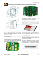
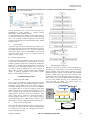
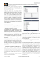
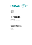
ISSN (Online) 2278-1021
ISSN (Print) 2319 5940
International Journal of Advanced Research in Computer and Communication Engineering
Vol. 4, Issue 8, August 2015
Interfacing and Controlling of Liquid Crystal
Display with Single Board Computer for
Communication Access Terminal
G.Hemavathi1, J.T.Pramod2
M.Tech Student, Dept of Electronics and Communication Engg, Madanapalle Institute of Technology & Science,
Madanapalle, A.P, India1
Asst Professor, Dept of Electronics and Communication Engg, Madanapalle Institute of Technology & Science,
Madanapalle, A.P, India2
Abstract: Advanced Composite Communication System is an IP based integrated communication system designed to
provide quick and reliable communication over Very Low Frequency, Medium Frequency, High Frequency and
Very/Ultra High Frequency bands on board naval ships and submarines for facilitating ship to ship, ship to shore and
ship to air communication. The Communication Access Terminal (CAT) is an important and integral part of ship
communication system. CAT is a PC104 Single Board Computer (SBC) based system for internal and external
communication. To provide visual information to the end user about line status, network status, information about
connected radio number, CAT number etc. As a part of CAT development, interfacing of LCD board to PC104 Mother
Board using RS232 based serial protocol is the main objective of this project. Programming the board is done using Qt
Creator in C++ language. The Liquid Crystal Display interfaced to the PC104 mother board is tested using Graphical
User Interface (GUI) application developed in Qt. The testing steps of display include 1) Displaying a preloaded logo
on startup. 2) Faulty display detection using full pixel illumination. The current CAT is a simplified version of earlier
CAT, which best suits for extreme weather conditions. The current CAT is designed so as to withstand the temperature
range of -400C to +850C, relative humidity up to 80 at 250C, vibration 10g.
Keywords: PC104 Mother Board, Communication Access Terminal, RS232 serial protocol, Qt creator, Graphical User
Interface, Liquid Crystal Display.
I.
INTRODUCTION
Now a day’s embedded systems are playing a vital role in
our surrounding areas such as electronic calculators, home
appliances, printers, scanners, digital cameras, displays
and many more. In many of the embedded system
applications programmable boards are developed to do
specific tasks according to the user requirements. Modern
embedded systems are often based on micro-controllers
but ordinary microprocessors are also still common,
especially in more complex systems.
Displaying data on different displays is also one of the
embedded system applications.
We have many different types of displays such as seven
segment displays, LCD etc. To show text on display we
should give control commands to display through any
single board containing microcontroller or microprocessor
by interfacing LCD to the Single Board Computer. In the
same way, to display the required information on LCD
one single board computer has chosen. In order to do that
Liquid Crystal Display is interfaced to PC104 Single
board computer to display text related to Communication
Access Terminal.
Communication Access Terminal is one of the sub-parts
of Advanced Composite Communication System.
Copyright to IJARCCE
II. HARDWARE AND SOFTWARE
REQUIREMENTS
A.
A. Hardware Requirements:
This project requires some hardware components such as
PC104 Mother board, KIB380 interface board, Compact
flash card, LCD, Power supply.
a) PC104 Mother Board:
The development of this project uses PC104 Mother
Board (CPC30401 version). Pre-installed operating
system supplied for PC104 is FDOS 6.22 operating
system and also it supports MSDOS, windows CE 5.0, CE
6.0, XPe, as well as QNX 6.3X and Linux 2.6 operating
systems. This board is designed for low power
consumption wide operating temperature range. All basic
components like memory, chipset, periphery controllers
and CPU are soldered on board providing very less
vibration and of protective conformal coating. Wide
variety of data display capabilities are offered by this
board provided industrial operating temperature range of
this board is -400C to +850C. The available memory, ports
etc. are shown in below figures:
In this figure if we observe, we can find number of jacks
for different connections, LED’s, Watch Dog Timer,
Reset button, PCI & ISA slots, CPU, BIOS, PCI to ISA
bridge, CPU and Buzzer etc.
DOI 10.17148/IJARCCE.2015.4890
414
ISSN (Online) 2278-1021
ISSN (Print) 2319 5940
International Journal of Advanced Research in Computer and Communication Engineering
Vol. 4, Issue 8, August 2015
Bottom view
Bottom view of interfacing board will as above. Ribbon
cables from jacks of PC104 connected here to the
corresponding ports for correct communication.
Top view of PC104 board
c) Compact flash card:
This device can be used as a bootable disk or can be
disabled in BIOS setup. The capacity of compact flash
memory chip is 4GB. We have the option of installing
operating system to this bootable disk.
Bottom view of PC104 board
This board also contains 1GB of on-board NAND flash,
256MB of RAM and Compact flash socket to insert the
compact flash card at the bottom side of the board.
This is the schematic view of PC104 board. The above
figures are top and bottom views. In top we can see onboard chips, jacks for different connections etc. In the
bottom view we have DDR
SDRAM of size 256MB, reserve BIOS, compact Flash
Socket, NAND Flash etc.
b) KIB380 interface board:
KIB380 makes interface of the processor module
available via standard PC connectors-VGA, Audio (Mic,
Line In, Line Out), four COM ports, two LAN, two USB,
two PS/2 for keyboard and mouse and LPT.
The compact flash memory chip will be look like this.
This is an industrial CF card to operate in wide
temperature ranges from -400C to +850C.
d) Liquid Crystal Display:
The LCD is an alphanumeric Liquid Crystal Display
designed for providing quick solution to any project. For
this LCD available protocols are RS232, TTL and I2C
protocols in the standard model.
Communication speed of this LCD is up to 115.2 kbps for
serial protocols and 100kbps for I2C protocol. On board
memory for this LCD are 40 custom characters which can
be saved and called for bar graphs, startup screens or
large numbers. The view of LCD will be as below:
Front view of LCD
Top view
In this top view we have all ports for connecting external
devices like keyboard, mouse, monitor, LAN connections.
Copyright to IJARCCE
By observing the top view of LCD we can find that it is a
pixel based display. On this display clarity is more
compared to other displays like seven segment display.
DOI 10.17148/IJARCCE.2015.4890
415
ISSN (Online) 2278-1021
ISSN (Print) 2319 5940
International Journal of Advanced Research in Computer and Communication Engineering
Vol. 4, Issue 8, August 2015
Back view of LCD
This is the bottom view of LCD here used parts are
highlighted by giving numbers. 1. General purpose
Input/output, 2. Serial DB9 connector,
3. Communication/power Header. In the name itself we
can find the working of those connectors. Important thing
here is do not apply voltage through pin 9 of the DB-9
connector and through the communication/power header
at the same time.
e)
Power supply:
The power supply to the PC104 mother board and LCD is
given through output of the Switch Mode Power Supply.
The SMPS output voltage is +5V, +12V DC voltage and
main power supply is given to the SMPS as input. These
board and LCD works at low DC voltage instead of
regular ac power supply.
B. Software Requirements:
To do this work required software is Qt. The present work
is done in Qt which supports PC104 board. Qt is a crossplatform, graphical application development toolkit that
enables us to compile and run applications on windows,
Mac OSx, Linux and different brands of unix. All tools
we need to develop applications are open sourced. It
offers APIs for many popular desktop and embedded
devices to desktop applications like printers, mobile
phones, coffee machines and so on.
III. IMPLEMENTATION
a)
Interfacing LCD to SBC:
In the process of interfacing LCD to SBC, first connect
LCD to SBC physically with the help of RS232 cable by
identifying corresponding ports. Give power supply to
LCD either through board or directly to LCD from SMPS
with voltage value of +5V. If power supply is giving from
SMPS it will be given to power header from pins 1 (Vcc)
and 4 (GND). If the LCD shows pre-loaded text on
display then ok, otherwise check for connections. After
power supply, text is showing on LCD means LCD is
working properly otherwise it is not working properly.
After interfacing LCD to SBC set basic values to LCD
like brightness, contrast, backlight on-time, baud rate etc.
b)
c)
Block diagram explanation
The figure shown below represents the block diagram of
Interfacing and controlling of LCD with PC104 Single
Board Computer. This block diagram consists of LCD,
KIB380 expansion module, PC104 mother board, SMPS
module, compact flash Type I/II card. Coming to the
explanation of the block diagram main power supply of
230V, 50Hzs is given to the SMPS module with the help
of power cable. SMPS will give us is connected to the
LCD and both the output DC voltage values are
connected to the PC104 mother board.
LCD Display
PS/2 Key
Board, PS/2
Mouse,
USB1,
USB2
VGA.
+5V
KIB 380 expansion Module
PS/2
USB
RS232
PC 104 Mother board
230V,
50Hzs
SMPS
Modul
e
+5V
+12V
Flow chart for writing code:
The above flow chart explains the steps of writing source
code using the software Qt. the computer language used
for writing the source code is C++ language. This code is
written to develop the GUI.
Copyright to IJARCCE
Compact Flash
Type I/II card
Figure1: Block diagram
DOI 10.17148/IJARCCE.2015.4890
416
ISSN (Online) 2278-1021
ISSN (Print) 2319 5940
International Journal of Advanced Research in Computer and Communication Engineering
Vol. 4, Issue 8, August 2015
All communication processes, instructions, commands
given by user are followed by PC104 mother board. On
top side of the PC104 board we have jacks which will
allow connecting ribbon cables.
Using these ribbon cables are somewhat difficult
compared to normal ports. For that reason again one more
KIB380 expansion module is connected to the mother
board. We can connect external devices having USB
ports, COM ports, and Ethernet ports to the expansion
module. LCD is connected to KIB380 expansion module
with the help of DB9 connector. Commands to this LCD
will be given by user with external devices and these
commands will process by PC104 board, then finally
given LCD to respond. In this diagram we can observe
one more component called compact flash Type I/II card.
It will be inserted at the bottom side of PC104 board at
specified socket. The memory size of this card is 4GB and
will work same as Hard Disk Drive in our normal
personal computer. The required files can be stored in this
card by USB devices.
Figure2: First page of GUI
d) Hardware testing method:
In this work main job is to test the working of LCD. In
order to work this LCD, first testing should be done o this
LCD. There are two testing methods are available.
1. Displaying a pre-loaded logo on startup.
To check whether LCD is working properly or not, LCD
manufacturer’s will provide their logo at startup screen,
means when power supply is given to LCD we should be
able to see their logo without fail, otherwise we can come
to conclusion that LCD is not working properly. There is
one more option that, it is possible to re-write the preloaded logo according to user wish. When power supply
is given user defined logo will display at the start-up time.
2.
Faulty
illumination.
display
detection
using
full
pixel
There is one more method to test the working of LCD. It
is by checking each and every pixel of LCD. To do this
work in the developed GUI with the help of source code,
one option is there, that is screen check. If we click on
that button each and every pixel, character by character
will highlight with brightness. If any pixel will not work it
will not highlight. Then we can know that there is some
problem.
IV. TESTING OF INTERFACE THROUGH GUI
Source code is written to develop the GUI. GUI
developed by writing source code will be as shown below.
If we observe the above GUI, it has so many pushbuttons,
line-edits and text-box. By clicking on the pushbutton the
corresponding action will takes place based on the type of
function.
In the process of developing GUI 3 windows are stacked.
These are called as stacked widgets.
Copyright to IJARCCE
Figure3: Second page of GUI
These will work same as going back and front in web
pages. This is used to get module number, Interface
Switching Board debug connection.
In this window we have back, front, refresh, stop and go
buttons and one line-edit to write the IP address. After
entering the link and clicking on GO button, we will get
the corresponding link.
V. SUMMARY, CONCLUSION AND FUTURE
SCOPE
The main purpose of this work was to interface and test
LCD with PC104 mother board. GUI was developed
using software Qt. But this GUI will show on computer
monitor connected to PC104 mother board. From GUI on
monitor we will send commands to LCD. This GUI was
developed for performing various operations of the
communication access terminal such as status display,
radio circuit number display, selected frequency value
display, characters and numbers send by user etc. Linux
operating system was flashed onto compact flash Type
I/II card by interfacing the PC104 mother board to a
computer. The GUI developed was copied as an
executable file onto the flash card for accessing the
features of the communication access terminal. The LCD
is tested as a final step by using the screen check button
through the GUI.
DOI 10.17148/IJARCCE.2015.4890
417
ISSN (Online) 2278-1021
ISSN (Print) 2319 5940
International Journal of Advanced Research in Computer and Communication Engineering
Vol. 4, Issue 8, August 2015
This work was done for developing the communication
access terminal as a single device for accessing voice and
data from other communication access terminals which
are connected to this. After complete development it
contains keypad for performing GUI operations which are
explained earlier. Up to this part LCD interfacing and
testing was done. By the reference of this work this
PC104 mother board has option of cascading of such
boards up to 4. If we cascade these boards communication
speed will increase up to 8 times compared to
communication speed with single board. Storage capacity
also increases.
REFERENCES
[1] LK162-12/VK162-12, Including the LK136-12-USB and VK162-12USB Technical Manual, Revision 4.2.
[2] http:// www.fastwel.com.
[3] CPC304 user manual.
[4] The waite groups object-oriented programming in Turbo C++ by
Robert Lafore.
[5] C++ GUI programming with Qt3 BRUCE PERENS OPEN
SOURCE SERIES by Jasmin Blanchette, Mark summer field.
[6] C++ Common knowledge Essential Intermediate programming by
Stephen C. Dewhurst.
[7] Foundation of Qt Development, Build sophisticated graphical
applications using one of the world’s most powerful multiplatform toolkits, by Johan Thellin.
[8] The C++ programming language, Third Edition by Bjarne stroustrup,
copyright @ 1997 by AT &T, published by Addison Wesley
Longman, Inc. ISBN 0-201-88954. All rights reserved.
[9] HLX800_hardware guide.pdf.
[10] 40456A_geode_lx_etx_rdk_pb.pdf
[11]http://www.moxa.com.
Copyright to IJARCCE
DOI 10.17148/IJARCCE.2015.4890
418