1
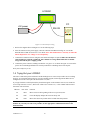
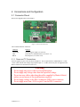
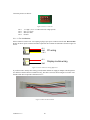
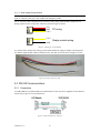
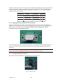
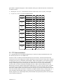
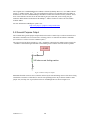
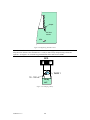
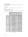
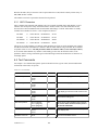
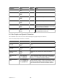
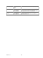
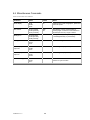
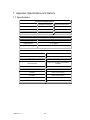
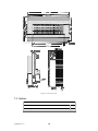
Distributed by:
www.Jameco.com ✦ 1-800-831-4242
The content and copyrights of the attached
material are the property of its owner.
Jameco Part Number 150957
LCD2041
User Manual
LCD2041 rev 2
1
Table of Contents
1.
Introduction ........................................................................................................................................... 4
1.1
1.2
1.3
1.4
2.
What it Does ..................................................................................................................................... 4
What it Does Not Do ........................................................................................................................ 4
Setup for Testing .............................................................................................................................. 4
Trying Out your LCD2041 ............................................................................................................... 5
Connections and Configuration............................................................................................................ 7
2.1 Connector Pinout .............................................................................................................................. 7
2.1.1 Power and I2C Connections .................................................................................................... 7
2.2 RS-232 Communications .................................................................................................................. 9
2.2.1 Connections ............................................................................................................................ 9
2.2.2 Applying Power via the RS-232 Connector.......................................................................... 10
2.2.3 Configuring RS-232 and I2C................................................................................................. 10
2.3 I2C Communications....................................................................................................................... 11
2.2 General Purpose Output.................................................................................................................. 12
3.
Displaying Text .................................................................................................................................... 14
3.1
3.2
3.3
3.4
4.
General ........................................................................................................................................... 14
The Built-In Character Font............................................................................................................ 14
Writing Text to the Display ............................................................................................................ 15
Text Commands.............................................................................................................................. 15
Bar Graphs and Special Characters .................................................................................................. 17
4.1 Command List ................................................................................................................................ 17
5.
Miscellaneous Commands ................................................................................................................... 20
5.1 Command List ................................................................................................................................ 20
6.
Appendix: Command Summary ......................................................................................................... 22
6.1 General ........................................................................................................................................... 22
6.2 Issuing Commands.......................................................................................................................... 22
6.3 On Numbers.................................................................................................................................... 22
6.3.1 ASCII Characters.................................................................................................................. 23
6.4 Text Commands.............................................................................................................................. 23
6.5 Bar Graphs and Special Characters ................................................................................................ 24
6.6 Miscellaneous Commands .............................................................................................................. 26
7.
Appendix: Specifications and Options ............................................................................................... 27
7.1 Specifications.................................................................................................................................. 27
7.2 Options ........................................................................................................................................... 28
8.
Appendix: Glossary ............................................................................................................................. 29
LCD2041 rev 2
2
LCD2041 rev 2
3
1. Introduction
Your LCD2041 has the following features:
20 column by 4 line text display
built-in font with provision for up to 8 user-defined characters
Speeds from 1200 bps to a lighting fast 19.2 Kbps over RS-232
Communicate over RS-232 or I²C
Use up to 16 modules on the same 2-wire I2C interface
Software controlled contrast
Backlight with configurable time-out setting up to 180 minutes
One general purpose output for a variety of applications
Horizontal or Vertical bar graphs
Variable power options, +5V or +8V to +15V
Extended temperature option.
Fits our Dual PC Bay insert without any modifications
1.1 What it Does
The LCD2041 is designed as the display unit for an associated controller. The controller may be anything
from a single board, special purpose microcontroller to a PC, depending on the application. This controller
is responsible for what you see on the screen of the LCD2041.
The LCD2041 provides a simple command structure to allow text and bar graphs to be displayed on the
screen. Text fonts are built in, and use standard ASCII mapping. Provision is made for up to 8 user-defined
characters.
The screen is backlit for low-light situations. Backlighting may be turned on or off under program control.
Contrast is adjustable to compensate for differing lighting conditions and viewing angles.
A general purpose output allows the controller to switch an electronic or electro-mechanical device by
issuing commands to the display unit. This can be used for controlling LEDs, relays, etc.
1.2 What it Does Not Do
The LCD2041 does not include bitmap graphics capability, except that permitted by defining special
characters. The LCD2041 does not include a keypad interface.
1.3 Setup for Testing
Before setting up your application you may want to try out the LCD2041. This is easily done with a PC.
Here's what you'll need:
A power cable with a 4 pin connector (same connector as used to connect a 3.5 inch floppy
drive). Do not connect the LCD2041 to an unmodified spare power connector in a PC. To
modify such a cable see section 2.1.1.
A 5 V power supply (for wide voltage models an 8 – 15 V supply is required).
a PC with a spare RS-232 port (COM1 or COM2).
A 9 or 25 pin RS-232 serial cable. If you use a 25 conductor cable you'll also need a 9 to 25
pin adapter.
LCD2041 rev 2
4
LCD2041
PC
+5V power
RS-232
Figure 1-1 Connections for Testing
1. Refer to the diagram above and Figure 2-1 for the following steps.
2. Wire the connector to the power supply. On most connectors the RED lead will go to +5V and the
BLACK lead to GND. See Section 2.1.1 for details. Note: The manufacturer's warranty is void if the
unit is subjected to over-voltage or reversed polarity.
3. Connect the LCD2041 to the PC using the serial cable and adapter if required. Make sure the RS-232
cable includes the required ground lead. There must be no voltage differential between the RS232 ground and the power supply ground.
4. Connect the power connector, making sure that the +5V goes to V+ as shown in Figure 2-2. Turn on the
power: the LCD backlight should come on and you should see a blinking cursor at the top left.
Now you're ready to try it out.
1.4 Trying Out your LCD2041
The unit is connected to power and the PC and the backlight is on. You're ready to make sure it's working
properly. To experiment with typing text, run a PC terminal program, such as Hyperterm. Make sure it's
configured to use the correct port. Set the baud rate to 19,200.
If you type characters on the keyboard, they should now appear on the LCD2041 screen. (It is normal for
text to wrap from line 1 to line 3, then to line 2 then 4. See section 3.4.1). A few common ASCII control
characters work as follows:
Character
Hex value
Function
LF
0x0A
Moves cursor to the beginning of the next (or previous) line.
FF
0x0C
Clears the display and puts the cursor at the top left
BS
0x08
Moves the cursor one position to the left and clears that position.
Note: These command characters are not guaranteed to work on other Matrix Orbital display
modules. If you want your code to be portable, use the appropriate commands listed later in the
manual instead.
LCD2041 rev 2
5
If you want to exercise some of the other features of the LCD2041 you'll need to write a program (in any
convenient language such as Basic or C) to issue the required command strings. Most terminal programs are
unable to issue the 0xFE character needed as a command prefix. You probably won't need to do this at the
initial testing stage.
If you've reached this point and operation is normal, you can be confident that your LCD2041 works
properly.
LCD2041 rev 2
6
2. Connections and Configuration
2.1 Connector Pinout
Refer to the diagram below for this chapter.
Figure 2-1 Electrical Connections
The LCD2041 has three connectors:
Connector
Function
2 pin header
4 pin
DB-9F
General purpose output (see section 0)
power and I2C communications (see section 2.1.1)
RS-232/power (see section 2.2.2)
2.1.1 Power and I2C Connections
Power is applied via pins 1 and 4 as shown in Figure 2-1. Power requirement for standard units is +5 VDC
±0.25V (units with the wide voltage range option require 8 – 15 VDC). Power may also be supplied via the
RS-232 connector as described in section 2.2.2.
Warning:
Do not apply any power with reversed polarization.
Do not apply any voltage other than the specified voltage.
Do not use any cables other than the cables supplied by Matrix Orbital,
unless you are aware of the modifications required.
Do not apply voltage to the DB-9 connector AND power connector
Do not apply more than +5Vdc to pin #9 on the DB-9 connector.
LCD2041 rev 2
7
Connector pinout is as follows:
1 2
3
4
Figure 2-2 Power connector
Pin 1
Pin 2
Pin 3
Pin 4
+5.0 VDC (+8 to +15 VDC with wide voltage option)
SCL (I2C clock)
SDA (I2C data)
Ground
2.1.1.1 Five Volt Modules
If the LCD2041 is used in a PC it is tempting to plug a spare power connector into the unit. Don't do this!
Wiring for the PC power connector and that required for the LCD2041 are different as shown in Figure 2-3
below.
+5 V
GND
+12 V
+5 V
GND
PC wiring
Display module wiring
Figure 2-3 Power Connector wiring differences
If you don't want to modify cable wiring yourself, Matrix Orbital can supply an adapter cable designed to
use with the LCD2041 when it's installed in a PC. The cable is wired as shown in Figure 2-4 below. Note
that this cable does not provide connections for I2C.
Figure 2-4 Five volt Power Cable
LCD2041 rev 2
8
2.1.1.2 Wide Voltage Range Modules
Note: Do not use this cable unless your display module has the "wide voltage range" option (option V). Use
of the 12 volt power cable with 5 volt modules will damage the module.
The 12 volt power cable is designed for use with wide voltage range display modules mounted in a PC.
Wiring required for the 12 volt power connector is shown in Figure 2-5 below.
+5 V
GND
+12 V
+12 V
GND
PC wiring
Display module wiring
Figure 2-5 Wiring for 12 volt modules
If you don't want to modify cable wiring yourself, Matrix Orbital can supply an adapter cable designed to
use with the display module when it's installed in a PC. The cable is wired as shown in Figure 2-6 below.
Figure 2-6 Twelve volt power cable
2.2 RS-232 Communications
2.2.1 Connections
A standard DB-9F is provided for RS-232 communications. Power may also be supplied via this connector
if desired. See Figure 2-7 for pin connections.
Figure 2-7 RS-232 and power connector
LCD2041 rev 2
9
The RS-232 connector on the PC cable is wired so that a standard “straight through” 9 pin D-sub cable may
be used to connect the module to a standard serial port such as COM ports on PCs. Note that this device
complies with the EIA232 standard in that it uses signal levels from ± 3V to ± 12V. It will not operate
correctly at TTL (0 to +5V) levels.
Pin Number
Direction
Description
LCD Host
2
Data from LCD
Data out (LCD)
Tx
Rx
3
Data to LCD
Data in (LCD)
Rx
Tx
5
-
Ground
gnd
gnd
2.2.2 Applying Power via the RS-232 Connector
The power connector on the PC cable is wired as shown in Figure 2-7. Power may be provided to the
module by pin 9 of the DB9 connector instead of through the 4-pin SIP. If power is to be applied using the
DB9, it must be a regulated 5Vdc supply. Note: This applies to wide voltage units (V and VPT
extensions) as well as to standard 5 volt units.
To use pin 9 as the power source, the user must solder the 5 volt jumper pad beside the DB9 connector. If
you have any further questions or concerns don’t hesitate to contact Matrix Orbital at [email protected].
Warning: Use this method of power up at your own risk. Application of a voltage to pin 9 greater
than 5.5 volts will cause immediate destruction of unit and void the warranty.
2.2.3 Configuring RS-232 and I2C
RS-232 baud rate and I2C address are configured by means of jumpers (see ).
Figure 2-8 RS-232 jumpers
LCD2041 rev 2
10
The module is supplied with jumpers J1 and J2 installed, which gives an RS-232 baud rate of 19200 and an
I2C address of 0x5C.
RS-232 port: J0, J1, J2 - control baud rate. RS-232 format is 8N1 (8 bits, no parity, one stop bit)
I²C port: J0, J1, J2, J3 - sets slave peripheral address
Baud Rate
1200
2400
9600
19200
1200
2400
9600
19200
Slave Address
J3
J2
J1
J0
50H
out
out
out
out
52H
out
out
out
in
54H
out
out
in
out
56H
out
out
in
in
58H
out
in
out
out
5AH
out
in
out
in
5CH
out
in
in
out
5EH
out
in
in
in
60H
in
out
out
out
62H
in
out
out
in
64H
in
out
in
out
66H
in
out
in
in
68H
in
in
out
out
6AH
in
in
out
in
6CH
in
in
in
out
6EH
in
in
in
in
2.3 I2C Communications
I²C communications runs at 100 kBps and supports up to 16 units on a single communications line. The
I2C data line operates on 5 volt CMOS levels.
The idea of ACK is to indicate when the data has been received correctly. ACK does not indicate data
incorrectly received. ACK simply fails to indicate when data is correctly received. Clearly, this is of limited
usefulness and even less so with Matrix Orbital modules. Matrix orbital modules are not capable of failing
to acknowledge an incorrectly received byte in response to that bytes transition. They are only capable of
failing to acknowledge the bytes following the byte, which was not received. To fully understand the
reasons for this one needs to understand something about how a Matrix Orbital module processes data.
Basically the reason why a Matrix Orbital module might fail to receive a byte correctly is that it was unable
to process the byte previous before the failed byte was transmitted. Because the module cannot possibly
know that it would be unable to store the byte before the next byte was received it cannot know to not ACK.
The reason for this situation in deference to situations you might be familiar with (i.e. memory chips, etc…)
is that the Matrix Orbital module employs a microprocessor to perform these data storage functions. A
memory chip takes care of these things entirely with in hardware subsystems that operate at the same speed
as the transmission themselves.
LCD2041 rev 2
11
The LCD2041 uses a standard Phillips 7bit address as defined by Phillips. How ever, we at Matrix Orbital
specify I2C address in 8bits. The 8th bit, least significant bit (LSB or Low Order Bit) of the 8bit address is
read/write bit. If we take a standard Phillips 7bit address of 45hex this would be in binary 1000101. This is
7bits. If one adds the read write bit to this 7bit address and you assume that you are writing one gets
10001010. Matrix Orbital would describe the Philips I2C address of 45hex as 8Ahex. The read address
would be 8Bhex.
For more information on Phillips I2C please visit…
http://www.ping.be/~ping0751/i2cfaq/i2cindex.htm
2.4 General Purpose Output
The LCD2041 has a general purpose output which can be used to control relays or other electronic devices.
This allows external devices to be turned on or off using your PC or controller and software commands.
(See sections 5.1.5 and 5.1.6 for the command syntax.)
The output is wired as shown in Figure 2-9. The + terminal is connected to the module positive supply, the
– terminal is connected through a 240 ohm current limiting resistor and the electronic switch to ground.
+ 5 VDC
-
+
load
240 ohm current limiting resistor
Figure 2-9 General Purpose Outputs
Maximum allowable current is 20 mA, which is enforced by the current limiting resistor. If the device being
switched has a resistance of 240 ohms or more the corresponding resistor may be shorted. Solder a small
jumper wire (wirewrap wire is good) between the two feedthrough holes as shown in Figure 2-10.
LCD2041 rev 2
12
Jumper
240 ohm
resistor
GPO
+-
Figure 2-10 Bypassing 240 ohm resistor
Note: The GPOs do not have any over current or over/under voltage protection so care must be taken when
using them. For instance if the external device is a relay it must be fully clamped (using a diode and
capacitor – see Figure 2-11) to absorb any generated back electro-motive force (EMF).
GPO
+
-
1N400 1
10 - 100 uF
Relay
coil
Figure 2-11 Clamping a Relay
LCD2041 rev 2
13
3. Displaying Text
This chapter describes the various text-display commands in detail. A quick reference summary of all text
commands is found in section 6.4.
3.1 General
Text is displayed on the LCD2041 using the built-in 5 x 7 dot matrix font (plus up to 8 user-defined
characters.
3.2 The Built-In Character Font
The LCD2041 includes a built-in 5 x 7 dot matrix font with the full range of ASCII characters plus a variety
of extended characters, as shown in Figure 3-1.
Figure 3-1 Character Set
LCD2041 rev 2
14
In addition to the built-in characters, users may define up to 8 special characters (which, once defined,
occupy positions 0x00 to 0x07 in the above chart). The LCD2041 does not have provision to download
other fonts.
3.3 Writing Text to the Display
When the display receives a character, it displays that character at the position currently defined. The next
character sent to the module then advances to the following position on the display. Characters are drawn
using the built-in font, and only characters defined in the font are actually displayed. Characters that are not
defined by the built-in font print as a space (i.e. the cursor is advanced for the next character).
The position where text is to be inserted is a character location stored in the LCD2041's volatile memory
and maintained internally by the LCD2041's firmware. This position is manipulated by the commands
shown in the following section.
3.4 Text Commands
In this section commands are identified by their names and decimal values. Hex and ASCII equivalents are
given in the summary (Table 6-1). Before issuing commands to the LCD2041 please read sections 6.2
and 6.3.
3.4.1 Auto line wrap on (254 67)
Enables automatic line wrapping. Note that this is not "word wrapping" and wraps may occur in the middle
of a word. Note that if auto line wrap and auto scroll are both off (default) text will wrap from line 1 to line
3 then 2 then 4. Default is OFF.
3.4.2 Auto line wrap off (254 68)
Disables automatic line wrapping.
3.4.3 Auto scroll on (254 81)
When auto scrolling is on, it causes the LCD2041 to shift the entire display’s contents up to make room for
a new line of text when the text reaches the scroll position (the bottom right character position). Default is
OFF.
3.4.4 Auto scroll off (254 82)
When auto scrolling is disabled, text will wrap to the top left corner of the display area instead of scrolling.
Existing text in the display area is not erased before new text is placed. A series of "spaces" followed by a
Cursor Home command may be used to erase the top line of text.
3.4.5 Set cursor position (254 71 [column] [row])
This command sets the cursor position (text insertion point) to the [column] and [row] specified. Columns
have values from 1 to 20 (0x01 to 0x14) and rows have values of 1 to 4 (0x01 to 0x04).
3.4.6 Send cursor home (254 72)
This command moves the cursor position (text insertion point) to the top left of the display area.
LCD2041 rev 2
15
3.4.7 Turn on underline cursor (254 74)
Turns on the underline cursor. The cursor shows the current text insertion point. Both underline and
blinking cursors may be turned on or off independently. The underline cursor is OFF by default.
3.4.8 Turn off underline cursor (254 75)
Turns off the underline cursor. Does not affect the blinking block cursor.
3.4.9 Turn on block (blinking) cursor (254 83)
Turns on the blinking block cursor. The cursor shows the current text insertion point. Both blinking and
underline cursors may be turned on or off independently. The block cursor is ON by default.
3.4.10 Turn off block (blinking) cursor (254 84)
Turns off the blinking block cursor. Does not affect the underline cursor.
3.4.11 Cursor left (254 76)
Moves the cursor one position to the left but does not erase any character that may be in that position. Note
that this command moves the text insertion point even if the cursor is turned off.
Note: A "destructive backspace", which erases the character to the left of the original position, may be done
by issuing the following sequence: cursor left, space, cursor left.
3.4.12 Cursor right (254 77)
Moves the cursor one position to the right but does not erase any character that may be in that position.
Note that this command moves the text insertion point even if the cursor is turned off.
LCD2041 rev 2
16
4. Bar Graphs and Special Characters
The LCD2041 includes the ability to draw bar graphs (either horizontal or vertical), large numbers, and
allows users to define up to eight special characters. Before issuing commands to the LCD2041 please
read sections 6.2 and 6.3.
Eight characters (ASCII values 0x00 to 0x07) are set aside for use with bar graphs, user defined characters,
and large digits. Since the same 8 characters are used for each function, the functions may not be used
simultaneously. The characters may be defined or redefined at any time by issuing the commands shown in
this section. Once defined, they may be used either by means of the bar graph commands, or by simply
issuing one of the ASCII values 0x00 to 0x07 (which is not prefixed by the command byte, 254).
4.1 Command List
4.1.1 Initialize wide vertical bar graph (254 118)
This command defines the 8 special/user characters to be blocks suitable for use in drawing wide (5 pixel)
vertical bar graphs. Any previously existing definitions will be lost. Once this command has been issued,
any number of vertical bar graphs may be drawn unless the characters are redefined by another command.
4.1.2 Initialize narrow vertical bar graph (254 115)
This command defines the 8 special/user characters to be blocks suitable for use in drawing narrow (2 pixel)
vertical bar graphs. Any previously existing definitions will be lost. Once this command has been issued,
any number of vertical bar graphs may be drawn unless the characters are redefined by another command.
4.1.3 Draw vertical bar graph (254 61 [column] [height])
Draws a vertical bar graph in [column] having a height of [height] pixels. The height may range from 0 to
32 (0x00 to 0x20) pixels. The necessary characters must first be initialized by either of the commands
shown in section 4.1.1 or 4.1.2, which will determine the width of the graph drawn. Graph may be erased by
drawing a bar graph of height = 0 in the same column.
4.1.4 Initialize horizontal bar graph (254 104)
This command defines the 8 special/user characters to be blocks suitable for use in drawing horizontal bar
graphs. Any previously existing definitions will be lost. Once this command has been issued, any number of
horizontal bar graphs may be drawn unless the characters are redefined by another command.
4.1.5 Draw horizontal bar graph (254 124 [column] [row] [dir] [length])
Draws a horizontal bar graph in [row] starting at [column] with a length of [length] pixels. [row] may have a
value of 0x01 to 0x04, column may range from 0x01 to 0x14 (0 to 20) and length may be from 0x00 to
0x64 (0 to 100) if the graph can extend the full width of the screen. Each column is 5 pixels wide (spaces
between the columns don't count).
[dir] specifies the direction: 0x00 goes from left to right, 0x01 goes from right to left.
4.1.6 Initialize large digits (254 110)
This command defines the 8 special/user characters to be blocks suitable for use in drawing large digits.
Any previously existing definitions will be lost. Once this command has been issued, any number of large
characters may be placed until the characters are redefined by another command.
LCD2041 rev 2
17
4.1.7 Place large digit 254 35 [col] [digit]
This command allows the large digits to be drawn on the LCD screen. Numbers of almost full display height
may be placed along side regular text on four row displays. The column number has a maximum value
which is less than the display width because the digits are all three columns wide.
Before using this command the Initialize Large Digits command must be issued to define the blocks
necessary to make up the digits. If regular text and large digits are mixed on one screen, the user should
always set the display cursor position before placing regular text because the creation of a large digit will
leave the cursor position to the bottom right of the large digit and not at the last regular text write position.
[col] can have values from 0x01 to 0x12 (1 to 18). [digit] has values from 0x00 to 0x09 (0 to 9).
4.1.8 Define custom character (254 78 [c] [8 bytes])
The LCD2041 allows up to 8 user defined (custom) characters. These characters occupy the first 8 (0x00 to
0x07) places in the character set (see Figure 3-1).
Custom characters occupy a 5 x 8 pixel matrix. Built-in characters are 5 x 7: the bottom row of pixels is
normally reserved for the underline cursor. The underline cursor should be turned off if the bottom row of
pixels forms part of a custom character.
The characters are defined by issuing the command 254 78 [c] followed by 8 bytes to define the character.
[c] is the character number (0x00 to 0x07). The 8 bytes are mapped as shown below:
MSB
LSB
*
*
*
1
2
3
4
5
Data Byte 1
*
*
*
6
7
8
9
10
Data Byte 2
*
*
*
11 12 13
14
15
Data Byte 3
*
*
*
16 17 18
19
20
Data Byte 4
*
*
*
21 22 23
24
25
Data Byte 5
*
*
*
26 27 28
29
30
Data Byte 6
*
*
*
31 32 33
34
35
Data Byte 7
*
*
*
36 37 38
39
40
Data Byte 8
A "1" bit indicates an on (black) pixel, a "0" bit indicates an off (clear) pixel.
Once defined, a character is displayed simply by issuing a value (0x00 to 0x07) corresponding to the
character number. The character will be laid out as follows:
LCD2041 rev 2
18
1
2
3
4
5
6
7
8
9
10
11
12
13
14
15
16
17
18
19
20
21
22
23
24
25
26
27
28
29
30
31
32
33
34
35
36
37
38
39
40
Cursor Line
Note: Custom characters will be erased if either the "initialize bar graph" or "initialize large digits"
commands are issued.
LCD2041 rev 2
19
5. Miscellaneous Commands
The commands listed in this chapter don't readily fit in any of the other categories, or are used in more than
one category. Before issuing commands to the LCD2041 please read sections 6.2 and 6.3.
5.1 Command List
5.1.1 Clear display (254 88)
This command clears the display and resets the text insertion point to the top left of the screen.
5.1.2 Set contrast (254 80 [contrast])
This command sets the display's contrast to [contrast], where [contrast] is a value between 0x00 and 0xFF
(between 0 and 255). Lower values cause "on" elements in the display area to appear lighter, while higher
values cause "on" elements to appear darker.
Lighting conditions will affect the actual value used for optimal viewing. Individual LCD2041 modules will
also differ slightly from each other in appearance. In addition, values for optimal viewing while the
LCD2041 backlight is on may differ from values used when backlight is off.
5.1.3 Backlight on (254 66 [minutes])
This command turns on the backlight for a time of [minutes] minutes. If [minutes] is zero (0), the backlight
will remain on indefinitely. Note: the factory default for backlight is on.
5.1.4 Backlight off (254 70)
This command turns the backlight of the LCD2041 off.
5.1.5 General purpose output off (254 86)
This command turns OFF the General Purpose Output (see section 0 for a description of the GPO). OFF
means that the "–" side of the output floats.
5.1.6 General purpose output on (254 87)
This command turns ON the General Purpose Output. ON means that the output is pulled low (ground via
240 ohms).
LCD2041 rev 2
20
5.1.7 Read module type (This Command does not work on the LCD2041)
This command will return, over the RS-232 interface, the model type value of the module. This command
returns a 1-byte hex value.Values for various modules at the time of this publication are as follows:
LCD0821 - 0x01
LCD2021 - 0x03
LCD1641 - 0x04
LCD2041 - 0x05
LCD4021 - 0x06
LCD4041 - 0x07
LK202-25 - 0x08
LK204-25 - 0x09
LK404-55 - 0x0A
VFD2021 - 0x0B
VFD2041 - 0x0C
VFD4021 - 0x0D
VK202-25 - 0x0E
VK204-25 - 0x0F
GLC12232 - 0x10
GLC12864 - 0x11
GLC128128 - 0x12
GLC24064 - 0x13
GLK12864-25 - 0x14
GLK24064-25 - 0x15
GLK128128-25 - 0x21
GLK12232-25 - 0x22
LK404-AT - 0x31
VFD1621 - 0x32
LK402-12 - 0x33
LK162-12 - 0x34
LK204-25PC - 0x35
LCD2041 rev 2
21
6. Appendix: Command Summary
6.1 General
The operation of the LCD2041 is controlled by a simple and consistent command set. Commands control
text display
graphics display
miscellaneous operating parameters
This chapter includes summary tables of all commands. Individual commands are discussed in detail in
Chapters 3 and 4 in the same sequence as in the following tables.
6.2 Issuing Commands
Commands are issued to the LCD2041 by the controller. In a test setup, commands can be issued to the
LCD2041 by means of a BASIC program, using the chr$( ) function. In the tables below, we've shown
commands in hex, ASCII and decimal form. All commands begin with the prefix character 0xFE (254
decimal). These commands are issued on the serial communications link (I2C or RS-232) at the currently
defined baud rate.
For example (using BASIC in a test setup), you could issue the command to clear the screen on the
LCD2041 by including the line:
PRINT#1,chr$(254);chr$(88)
in your BASIC program. Or with C you could (using Zcomm serial library)
ZComm1->WriteCommByte(0xfe);
ZComm1->WriteCommByte('X');
6.3 On Numbers
Like all computerized devices, the LCD2041 operates with commands and values in the form of binary
numbers. These binary numbers are arranged in 8 digit (i.e. 8 bit) groups called bytes. The decimal value of
a byte may have any value from 0 to 255.
Bytes are usually specified in either decimal or hexadecimal (base 16) form for convenience, since binary
numbers are confusing to deal with directly. Hexadecimal (hex) numbers are particularly convenient
because exactly two hexadecimal digits make up one byte, each hex digit representing 4 binary digits (4
bits) as shown here:
LCD2041 rev 2
Binary
Hex
Decimal
Binary
Hex
Decimal
0000
0
0
1000
8
8
0001
1
1
1001
9
9
0010
2
2
1010
A
10
0011
3
3
1011
B
11
0100
4
4
1100
C
12
0101
5
5
1101
D
13
0110
6
6
1110
E
14
0111
7
7
1111
F
15
22
Based on the table, the byte 01001011 can be represented in hex as 4B, which is usually written as any of
4Bh, 4BH, 4B hex or 0x4B.
The numbers can also be expressed in decimal form if preferred.
6.3.1 ASCII Characters
Since computers deal internally with numbers only, but externally with both letters and numbers, several
schemes were developed to "map" written characters to numeric values. One such scheme has become
universal, the American Standard Code for Information Interchange, or ASCII. ASCII tables are readily
available from a number of sources. A few examples will do here:
The letter
A
has a value of
65 decimal or
41 hex
The letter
a
has a value of
97 decimal or
61 hex
The number
0
has a value of
48 decimal or
30 hex
The number
9
has a value of
57 decimal or
39 hex
This gives rise to the possibility of confusion when parameters are being set on the LCD2041 For example,
the GPO ON and OFF commands use a number to indicate which GPO is being controlled. We're told that
acceptable values are 0 to 6. All such parameters must use numeric values (i.e. the actual byte values).
If we send the ASCII number 0 by mistake it will actually give the value 48 decimal (30 hex) to the
parameter, which is wrong. In the tables given in the following sections ASCII characters are shown as 'A',
with single quotes.
6.4 Text Commands
See Chapter 3 for command descriptions. Syntax in the tables below is given in hex, decimal and decimal
with ASCII, in that order, one per line.
Table 6-1 Text Commands
Command
Syntax
Default
Notes
Auto line wrap on
FE 43
254 67
254 'C'
off
Enables line wrapping (not word wrap).
Auto line wrap off
FE 44
254 68
254 'D'
off
Disables line wrapping.
Auto scroll on
FE 51
254 81
254 'Q'
off
Enables scroll at bottom of screen. Text will
push display up one line to make room for new
line.
Auto scroll off
FE 52
254 82
254 ‘R’
off
Disables auto scroll. Text will wrap to top left
and overwrite existing text.
Set cursor position
FE 47 [col] [row]
254 71 [col] [row]
254 'G' [col] [row]
n/a
Moves cursor to the specified column and row.
The cursor marks the text insertion point in
this and all commands.
Send cursor home
FE 48
254 72
254 'H'
Underline cursor on
FE 4A
LCD2041 rev 2
This command moves the cursor to the top left
of the display area.
off
23
Turns on the underline cursor.
Command
Syntax
Default
Notes
254 74
254 'J'
R
Underline cursor off
FE 4B
254 75
254 'K'
R
Turns off the underline cursor.
Block cursor on
FE 53
254 83
254 'S'
on
R
Turns on the blinking block cursor.
Block cursor off
FE 54
254 84
254 'T'
R
Turns off the blinking block cursor.
Cursor left
FE 4C
254 76
254 'L'
Moves the cursor one position to the left. If the
cursor is already at the beginning of a line it will
move to the end of the other line.
Cursor right
FE 4D
254 77
254 'M'
Moves the cursor one position to the right. If the
cursor is already at the end of a line it will move
to the beginning of the other line.
6.5 Bar Graphs and Special Characters
The commands in this section are used to define and display bar graphs and special characters.
Table 6-2 Bar Graph and Special Character Commands
Command
Syntax
Notes
Initialize thick vertical
bar graph
FE 76
254 118
254 'v'
Initializes the user character set to make wide vertical bar
graphs.
Initialize thin vertical
bar graph
FE 73
254 115
254 's'
Initializes the user character set to make narrow vertical bar
graphs.
Initialize horizontal
bar graph
FE 68
254 104
254 'h'
Initializes the user character set to make horizontal bar
graphs.
Draw vertical bar
graph
FE 3D [col][length]
254 61 [col][length]
254 '=' [col][length]
Draws a vertical bar graph at column [col] of length [length].
Length is measured in pixels (0x00 to 0x20). User must first
use the 'v' or 's' command to initialize characters.
Draw horizontal bar
graph
FE 7C [c][r][d][length]
254 124 [c][r][d][length]
254 '|' [c][r][d][length]
Draws a horizontal bar graph starting at column [c] on row [r]
with direction [d] (0 is right, 1 is left) of length [length]. Length
is measured in pixels (0x00 to 0x64 if starting in column 1).
User must first use the 'h' command to initialize characters.
LCD2041 rev 2
24
Initialize large digits
FE 6E
254 110
254 'n'
Initializes the user character set to make large digits.
Place large digits
FE 23 [col] [digit]
254 35 [col] [digit]
254 '#' [col] [digit]
Place large digit number [digit] in column [col] of the display.
Cursor moves to bottom right of large digit. [digit] is 0x00 to
0x09, [col] is 0x01 to 0x12 (i.e. 1 to 18 decimal).
Define custom
character
FE 4E [c][8 bytes]
254 78 [c][8 bytes]
254 'N' [c][8 bytes]
Defines one of 8 custom "user" characters. Character
number is [c] between 0x00 and 0x07. The 8 bytes are
described in section 4.1.8.
LCD2041 rev 2
25
6.6 Miscellaneous Commands
Table 6-3 Miscellaneous Commands
Command
Syntax
Default
Notes
Clear display
FE 58
254 88
254 'X'
n/a
Clears screen of text and graphics, places text
cursor at top left.
Set contrast
FE 50 [contrast]
254 80 [contrast]
254 'P' [contrast]
0x80
128
Sets display contrast. Compensates for
viewing angle. Contrast is a value between 0
and 255 (hex 0 to FF). Larger = darker.
Backlight on
FE 42 [minutes]
254 66 [minutes]
254 'B' [minutes]
on
Backlight will stay on for [minutes]. If [minutes]
= 0 backlight will stay on permanently.
Backlight off
FE 46
254 70
254 'F'
on
Turns off backlight.
General purpose
output off
FE 56
254 86
254 'V'
off
Turns the general purpose output OFF.
General purpose
output on
FE 57
254 87
254 'W'
off
Turns the general purpose output ON.
Read module type
FE 37
254 55
254 '7'
see table
See table in section 5.1.7. This command
returns a 1-byte hex value.
LCD2041 rev 2
26
7. Appendix: Specifications and Options
7.1 Specifications
Environmental Specifications
Standard Temperature
Extended Temperature
Operating Temperature
0°C to +50°C
-20°C to +70°C
Storage Temperature
-20°C to +70°C
-40°C to +85°C
Operating Relative Humidity 90% max non-condensing
90% max non-condensing
Electrical Specifications
Supply Voltage
4.75 - 5.25 Vdc (optional 8 – 15 VDC)
Supply Current
11 mA typical
Supply Backlight Current
90 mA typical
Optical Characteristics
LCD2041 rev 2
Number of Characters
80 (20 characters by 4 lines)
Matrix format
5 x 7 with underline
Display Area
76.3 x 25.20 mm XxY
Character Size
2.95 x 4.75 mm (XxY), not including
underline
Character Pitch
3.55 mm
Line pitch
5.35 mm
Dot Size
0.55 x 0.55 mm (XxY)
Dot Pitch
0.60 x 0.60 mm (XxY)
LED Backlight Life
100,000 hours typical
Color of Illumination
Yellow Green
27
Figure 7-1 Physical Layout
7.2 Options
Options Available on LCD2041
Extended Temperature
E
Wide Voltage
V
LCD2041 rev 2
28
8. Appendix: Glossary
ASCII
American Standard Code for Information Interchange. A 7 bit binary code
representing the english alphabet, decimal numbers and common punctuation
marks. "Also includes control characters" such as carriage return or end of text.
An 8 bit superset of the standard ASCII codes is often used today to include
foreign characters and other symbols. These supersets are often called
extended ASCII character sets.
Backlight
A backlit display is illuminated from behind to provide nighttime and improved
daytime readability.
Baud Rate
The (data and signaling) bit transmission rate of an RS232 device.
Binary Number A number written using binary notation which only uses zeros and ones
Bit
The smallest unit of information a computer can work with. Each bit is either 0
or 1. Binary digit.
Bitmap
A representation, consisting of rows and columns of dots, of a graphics image
in computer memory. The value of each dot (whether it is filled in or not) is
stored in one or more bits of data.
Byte
A grouping of eight binary bits
CCFL
Cold Cathode Fluorescent Lamp. A high brightness backlighting source
consists of a fluorescent tube powered by a high voltage A.C. source.
Configuration
The way a system is set up, or the assortment of components that make up the
system. Configuration can refer to either hardware or software, or the
combination of both.
Contrast
The ratio of luminance between the light state of the display to the dark state of
the display.
Controller
The microcontroller or PC used to control the Matrix Orbital display unit.
DB-9
The designation of a connector used in the RS232 interface: 9 pin connector
Firmware
Software (programs or data) that has been written onto read-only memory
(ROM). Firmware is a combination of software and hardware. ROMs, PROMs
and EPROMs and flash EEPROMs that have data or programs recorded on
them are firmware.
Font
A design for a set of characters. A font is the combination of typeface and other
qualities, such as size, pitch, and spacing.
Font Metric
A definition of where font is to be placed, such as margins and spacing
between characters and lines.
Hexadecimal
Refers to the base-16 number system, which consists of 16 unique symbols:
the numbers 0 to 9 and the letters A to F. For example, the decimal number 15
is represented as F in the hexadecimal numbering system. The hexadecimal
system is useful because it can represent every byte (8 bits) as two
consecutive hexadecimal digits. It is easier for humans to read hexadecimal
numbers than binary numbers.
I²C
Short for Inter-IC, a type of bus designed by Philips Semiconductors in the
early 1980s, which is used to connect integrated circuits (ICs). I²C is a multimaster bus, which means that multiple chips can be connected to the same
bus and each one can act as a master by initiating a data transfer.
Interface
A means by which two systems interact.
LCD2041 rev 2
29
LCD
Liquid Crystal Display
Module Type
Value
This refers to the model number of the module.
Pixel
The smallest individually controllable element of a display.
Pre-Generated
Fonts
Pre-determined fonts which can be downloaded into graphic liquid crystal
displays.
Primitive
A low-level object or operation from which higher-level, more complex objects
and operations can be constructed. In graphics, primitives are basic elements,
such as lines, curves, and polygons, which you can combine to create more
complex graphical images
RS-232
Short for recommended standard-232C, a standard interface approved by the
Electronic Industries Association (EIA) for connecting serial devices.
Scroll
To view consecutive lines of data on the display screen. The term scroll means
that once the screen is full, each new line appears at the bottom edge of the
screen and all other lines move up one position.
Serial Number
A number that is one of a series and is used for identification of the module
Serial Port
A port, or interface, that can be used for serial communication, in which only 1
bit is transmitted at a time.
Version
Number
This refers to the firmware revision number of the module.
Volatile
Memory
Temporary memory. Once the power supply is turned off volatile memory is
then erased.
LCD2041 rev 2
30