1
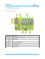
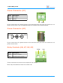
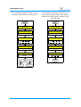
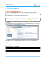
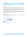
1-Wire Relay Card
User Manual
February 2015
1-Wire Relay Card
Table of Contents
1
Features
3
2
Technical Specifications
3
3
1-Wire Relay Card
Board Overview
1-Wire Terminal Block Connector (K3)
1-Wire RJ45 Connectors (K4, K5)
1-Wire Slave Chip Power Selection (JP1)
Power Connector (K1)
Power Connector (K2)
Relay Contacts (K6, K7, K8, K9)
Digital Inputs
1-Wire Connectivity
Communications Protocol
4
4
5
5
5
6
6
6
7
7
8
4
Software Support
1-Wire Automation Server
ows
owfs
10
10
10
11
5
Legal Information
Disclaimer
Trademarks
12
12
12
6
Contact Information
12
Revision History
Date
Authors
Description
2013-07-28 Peter S'heeren
Initial release.
2015-02-17 Peter S'heeren
Added section about 1-Wire Automation Server
software support.
Second release.
2
User Manual
1-Wire Relay Card
1 Features
▪
4 relay outputs capable of switching 4 A
at 230 V AC.
▪
4 opto-isolated digital inputs 5-30 V DC
10 mA max.
▪
Power supply 12 V DC 200 mA max.
▪
Power connection via coaxial DC plug or
screw terminals.
▪
1-Wire interface is galvanically isolated
from the main power supply to avoid
ground loops.
▪
1-Wire connections via standardized
RJ45 jacks or screw terminals.
▪
The 1-Wire slave chip can be powered parasitically, using an external 5 V line or using
the on-board 5V supply.
2 Technical Specifications
Weight
98 g
Dimensions
117 mm x 86 mm x 19 mm (W x D x H)
User Manual
3
1-Wire Relay Card
3 1-Wire Relay Card
Board Overview
1
2
3
4
5
6 7
Mark
Label
1
K3
1-Wire bus terminal block connector
2
JP1
Power selection
3
K6, K7,
K8, K9
Relay contacts
4
K5
1-Wire bus RJ45 connector
5
K4
1-Wire bus RJ45 connector
6
K1
12V power supply
7
K2
12V power supply
8
4
8
Description
Digital inputs
User Manual
1-Wire Relay Card
1-Wire Terminal Block Connector (K3)
Mark
Description
GND
Ground
1W
1-Wire DQ line (data)
5V
5 V supply
GND 1W 5V
1-Wire RJ45 Connectors (K4, K5)
Mark
Description
1
Unassigned
2
+5 V power
3
Unassigned
4
1-Wire DQ (data)
5
1-Wire ground
6
Unassigned
7
Unassigned
8
Unassigned
1 2 3 4 5 6 7 8
1 2 3 4 5 6 7 8
Plug
top view
Receptacle
front view
All eight pins are routed between the two connectors. The relay card doesn't use the
unassigned lines.
1-Wire Slave Chip Power Selection (JP1)
Mark
Description
1
Parasitic power
2
External power
3
Power derived from 12V
1
2
3
This jumper determines how the 1-Wire slave chip is powered:
▪
Parasitic power: the 1-Wire slave uses an internal capacitor as its power source. The
capacitor is charged during idle time (DQ line held high) and provides power during
bus activity. The 5 V line (K3, K4, K5) is not applicable.
▪
External power: the 1-Wire slave draws power from the 5V line. Be sure the voltage
is provided to one of the 1-Wire connection points (K3, K4, K5).
▪
Power derived from 12 V: The 5 V for the 1-wire slave chip is derived from the 12 V
power supply (K1 or K2).
See the 1-Wire specification for more information about parasitic power.
User Manual
5
1-Wire Relay Card
Power Connector (K1)
Mark
Description
12V
12 V input
GND
Ground
12V
GND
If you connect the 12 V power source to this connector then you must not connect a 12 V
power source to K2. The corresponding pins of K1 and K2 are interconnected.
Power Connector (K2)
Polarity
If you connect the 12 V power source to this connector then you must not connect a 12 V
power source to K1.
Relay Contacts (K6, K7, K8, K9)
COM
Mark
Description
COM
Common contact
NO
NO
Normally open contact
These connectors are wired to the contacts of the relays.
Each relay can switch at most 4 A at 230 V AC.
6
User Manual
1-Wire Relay Card
Digital Inputs
Mark
Description
1
Input 1
2
Input 2
3
Input 3
4
Input 4
GND1
Ground
GND2
Ground
1
2
3
4 GND1 GND2
GND1 and GND2 are interconnected.
The max. values for each input are 5-30 V DC 10 mA.
1-Wire Connectivity
The relay card provides three connection
points for 1-Wire cabling and wiring.
5V 1W GND
The terminal block connector is typically
used for wiring the relay card to an
AbioWire or another 1-Wire adapter.
Terminal
block
connector
K3
The RJ45 receptacles provide a means to
set up a 1-Wire bus in daisy chain using
UTP cables.
K4
RJ45
receptacle
K5
RJ45
receptacle
1
User Manual
2
3
4
5
6
7
8
7
1-Wire Relay Card
Communications Protocol
The 1-Wire slave function on the relay card is a Maxim DS2408 chip.
See the Maxim DS2408 datasheet for more information about the 1-Wire slave chip.
The family code of the DS2408 is 29h. Since the family code alone doesn't uniquely
identify a 1-Wire Relay Card device, the host system must associate the full 8-byte ROM
code with the device.
The host system is expected to use Standard speed when communicating with the relay
card over the 1-Wire bus.
PIO channels 1-4 of the DS2408 use negative logic to control the relays. To turn on a
relay, write zero to the corresponding PIO channel. To turn off a relay, write one to the
corresponding PIO channel.
PIO channels 5-8 are connected to the input terminals. You must always program
these PIO channels as logic one.
8
User Manual
1-Wire Relay Card
The following diagram shows how to
write byte value F6h to the relay card.
The following diagram shows how to
read the PIO logic states, PIO output
latches and PIO activity latches from
the relay card.
start
start
1-Wire Reset
1-Wire Reset
1-Wire Write Byte
1-Wire Write Byte
55h (match ROM)
55h (match ROM)
1-Wire Write Bytes
1-Wire Write Bytes
29h xxh xxh xxh
xxh xxh xxh xxh
29h xxh xxh xxh
xxh xxh xxh xxh
1-Wire Write Bytes
1-Wire Write Bytes
5Ah F6h 09h
F0h 88h 00h
1-Wire Read Byte
1-Wire Read Bytes
result
xxh xxh xxh
result equals AAh?
stop
Y
stop
User Manual
N
error
9
1-Wire Relay Card
4 Software Support
1-Wire Automation Server
Use client command Device PIO to control the state of the relays. For example:
dev "29-11BD2A" pio off 1 4 on 2
This command turns on relays 1 and 4 and turns off relay 2.
To determine the state of the inputs, issue client command Device Sense:
dev "29-11BD2A" sense force
dev "29-11BD2A" sensed ds2408 "2015-02-15 10:10:20 11110010 11110010
10001111 reset external"
The most significant four bits of the sensed values (marked in yellow) represent the state
of the inputs.
The 1-Wire Automation Server GUI program offers a comfortable way to work with the 1Wire Relay Card in a graphical desktop environment:
In the above picture, the first relay has been turned on and all four inputs are high.
ows
Software package ows v1.3.0 and later includes program owspio. This program enables
you to fully control the relay card.
Example invocations of the program:
# ./owspio -lu -id 29-11BD2A -off 1 4 -on 2
This command turns on relays 1 and 4 and turns off relay 2.
# ./owspio -lu -id 29-11BD2A -read 10
This command reads the state of the four relays and the sensed state of the four inputs
ten times.
10
User Manual
1-Wire Relay Card
owfs
It's assumed you're using the filesystem client of the owfs package. In the examples it's
supposed you've specified /mnt/onewire/ as the mount directory for the 1-Wire file
system.
Since owfs inverts all values written to PIO channels, the default negative logic becomes
positive logic.
# echo "1" > /mnt/onewire/29.2ABD11000000/PIO.0
This command turns on relay 1. Note the use of positive logic as opposed to the real
value zero that's written to the PIO latch in the DS2438.
# echo "0" > /mnt/onewire/29.2ABD11000000/PIO.3
This command turns off relay 4.
# cat /mnt/onewire/29.2ABD11000000/PIO.0
This command reads the latched value for relay 1.
# cat /mnt/onewire/29.2ABD11000000/sensed.0
This command reads the sensed value of relay 1.
# cat /mnt/onewire/29.2ABD11000000/sensed.4
This command reads the sensed value of input 1 on the relay card.
# cat /mnt/onewire/29.2ABD11000000/sensed.7
This command reads the sensed value of input 4 on the relay card.
User Manual
11
1-Wire Relay Card
5 Legal Information
Disclaimer
Axiris products are not designed, authorized or warranted to be suitable for use in space,
nautical, space, military, medical, life-critical or safety-critical devices or equipment.
Axiris products are not designed, authorized or warranted to be suitable for use in
applications where failure or malfunction of an Axiris product can result in personal
injury, death, property damage or environmental damage.
Axiris accepts no liability for inclusion or use of Axiris products in such applications and
such inclusion or use is at the customer's own risk. Should the customer use Axiris
products for such application, the customer shall indemnify and hold Axiris harmless
against all claims and damages.
Trademarks
All product names, brands, and trademarks mentioned in this document are the property
of their respective owners.
6 Contact Information
Official website: http://www.axiris.eu/
12
User Manual