1
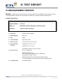
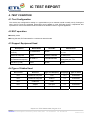
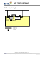
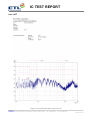
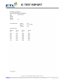
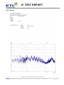
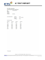
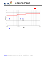
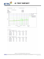
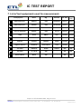
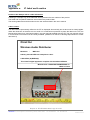
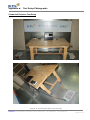
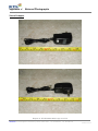
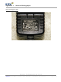
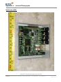
IC TEST REPORT Table of Contents IC Measurement Report 1. Introduction 2. Product Information 3. Description of Tests 4. Test Condition 5. Test Results 5.1 Summary of Test Results 5.2 Conducted Emissions Measurement 5.3 Radiated Emissions Measurement 6. Sample Calculation 7. List of test Equipment used for Measurement Appendix A. IC Label and Location Appendix B. Test Setup Photographs Appendix C. External Photographs Appendix D. Internal Photographs Appendix E. Block Diagram Report no. ETLE150630.0822, Page 2 of 21 Head Office: 114, Gasan digital 2-ro, Geumcheon-gu, Seoul, 153-803, Korea Tel : 82-2-858-0786 Fax : 82-2-858-0788 ETLQP-21-F24-0 IC TEST REPORT IC MEASUREMENT REPORT Scope – Measurement and determination of electromagnetic emission(EME) of radio frequency devices including intentional radiators and/or unintentional radiators for compliance with the technical rules General Information Applicant Name : Cinet Inc Address Attention : 8616 Phoenix Drive, Manassas, VA 20110, USA : Aaron K. Han / President EUT Type : Wireless Audio Distributor Model Number : WAD-104 S/N : NONE Test Procedure : ANSI C63.4-2009 Dates of Tests : June 30, 2015 to July 02, 2015 Environmental of Tests: Temperature: (25.0 ± 3.7) °C Humidity: (57 ± 11) % R.H. Atmospheric Pressure: (99.8 ± 0.2) kPa Place of Tests : ETL Inc. Testing Lab. Radiated Emission test 1; 97-4, Gureomae-gil, Seosin-myeon, Hwaseong-si, Gyeonggi-do, 445-882, Korea Radiated Emission test 2 and Conducted Emission test; 114, Gasan digital 2-ro, Geumcheon-gu, Seoul, 153-803, Korea Test Report No. : ETLE150630.0822 Report no. ETLE150630.0822, Page 3 of 21 Head Office: 114, Gasan digital 2-ro, Geumcheon-gu, Seoul, 153-803, Korea Tel : 82-2-858-0786 Fax : 82-2-858-0788 ETLQP-21-F24-0 IC TEST REPORT 1. INTRODUCTION The measurement test for radiated and conducted emission test was conducted at the ETL Inc. The site is constructed in conformance with the requirements of the ANSI C63.4-2009 and CISPR Publication 16. The measurement procedure described in American National Standard for Method of Measurement of RadioNoise Emission from Low-Voltage Electrical and Electronic Equipment in the Range of 9 kHz to 40 GHz (ANSI C63.4-2009) was used in determining radiated and conducted emissions from the Cinet Inc Model: WAD-104 Report no. ETLE150630.0822, Page 4 of 21 Head Office: 114, Gasan digital 2-ro, Geumcheon-gu, Seoul, 153-803, Korea Tel : 82-2-858-0786 Fax : 82-2-858-0788 ETLQP-21-F24-0 IC TEST REPORT 2. PRODUCT INFORMATION 2.1 Equipment Description The Equipment Under Test (EUT) is the Wireless Audio Distributor (model: WAD-104). The model WAD-104 is basic model that was tested. 2.2 General Specification - Power Adapter: DC 5 V, 2.0 A - Audio Input: Stereo RCA x 4, 3 Vp-p, SNR: 99 dB - USB: USB 2.0 Type-A - Network: RJ-45 type, IEEE1588 compliant, 10/100/1000 Mbps Gigabit Ethernet - Dimension (W x H x D): 110 mm x 42 mm x 100 mm - Weight: About 500 g - High Internal Frequency: OSC 25 MHz Report no. ETLE150630.0822, Page 5 of 21 Head Office: 114, Gasan digital 2-ro, Geumcheon-gu, Seoul, 153-803, Korea Tel : 82-2-858-0786 Fax : 82-2-858-0788 ETLQP-21-F24-0 IC TEST REPORT 3. DESCRIPTION OF TESTS 3.1 Conducted Emission Measurement Conducted emissions measurements were made in accordance with ICES-003 Issue 5. The measurements were performed over the frequency range of 0.15 MHz to 30 MHz using a 50 Ω/50 μH LISN as the input transducer to a Spectrum Analyzer or a Test Receiver. The measurements were made with the detector set for "Peak" amplitude within a bandwidth of 9 kHz or for "quasi-peak" within a bandwidth of 9 kHz. The line-conducted emission test is conducted inside a shielded anechoic chamber room with 1 m x 1.5 m x 0.8 m wooden table which is placed 40 cm away from the vertical wall and 1.5 m away from the side wall of the chamber room. Two LISN are bonded to the shielded room. The EUT is powered from the LISN and the support equipment is powered from the other LISN. Power to the LISNs are filtered by a noise cut power line filters. All electrical cables are shielded by braided tinned steel tubing with inner 1.2 cm. If the EUT is a DC-powered device, power will be derived from the source power supply it normally will be powered from and these supply lines will be connected to the LISN. Non-inductive bundling to a 1 m length shortened all interconnecting cables more than 1 m. Sufficient time for the EUT, support equipment, and test equipment was allowed in order for them to warm up to their normal operating condition. The RF output of the LISN was connected to the EMI Test Receiver to determine the frequency producing the maximum emission from the EUT. The frequency producing the maximum level was reexamined using to set Quasi-Peak mode by manual, after scanned by automatic Peak mode from 0.15 MHz to 30 MHz. The bandwidth of the spectrum analyzer was set to 9 kHz. The EUT, support equipment, and interconnecting cables were arranged and manipulated to maximize each emission. Photographs of the worst-case emission can be seen in photographs of conducted emission test setup in Appendix B. Report no. ETLE150630.0822, Page 6 of 21 Head Office: 114, Gasan digital 2-ro, Geumcheon-gu, Seoul, 153-803, Korea Tel : 82-2-858-0786 Fax : 82-2-858-0788 ETLQP-21-F24-0 IC TEST REPORT 3.2 Radiated Emission Measurement Radiated emission measurements were made in accordance with ICES-003 Issue 5. The measurements were performed over the frequency range of 30 MHz to 40 GHz (or 5th harmonic of the highest frequency) in using antenna as the input transducer to a spectrum analyzer or a field intensity meter. The measurements below 1 GHz were made with the detector set for "Quasi-peak" within a bandwidth of 120 kHz. The measurements above 1 GHz were made with the detector set for "Peak and Average" within a bandwidth of 1 MHz. Preliminary measurements were made at 3 m using broadband antennas, and spectrum analyzer to determined the frequency producing the maximum emission in shielded room. Appropriate precaution was taken to ensure that all emission from the EUT were maximized and investigated. The system configuration, mode of operation, turntable azimuth and height with respect to the antenna were noted for each frequency found. The spectrum was scanned from 30 MHz to 1 000 MHz using Log-Bicon antenna. Above 1 GHz, linearly polarized double ridge horn antennas were used. Final measurements were made open site or SVSWR chamber at 10 m and 3 m. The test equipment was placed on a styrofoam table. Sufficient time for the EUT, support equipment, and test equipment was allowed in order for them to warm up to their normal operating condition. Each frequency found during pre-scan measurements was re-examined by manual. The EUT, support equipment and interconnecting cables were re-configured to the set-up producing the maximum emission for the frequency and were placed on top of a 0.8 m high nonmetallic 1 m x 1.5 m table. The EUT, support equipment, and interconnecting cables were re-arranged and manipulated to maximize each emission. The turntable containing the system was rotated; the antenna height was varied 1 m to 4 m and stopped at the azimuth or height producing the maximum emission. Each emission was maximized by: varying the mode of operation to the EUT and/or support equipment and changing the polarity of the antenna, whichever determined the worst-case emission. Photographs of the worst-case emission can be seen in Photographs of the worst-case emission test setup can be seen in Appendix B. Report no. ETLE150630.0822, Page 7 of 21 Head Office: 114, Gasan digital 2-ro, Geumcheon-gu, Seoul, 153-803, Korea Tel : 82-2-858-0786 Fax : 82-2-858-0788 ETLQP-21-F24-0 IC TEST REPORT 4. TEST CONDITION 4.1 Test Configuration The device was configured for testing in a typical fashion (as a customer would normally use it). During the tests, the EUT and the supported equipments were installed to meet ICES-003 Issue 5 requirement and operated in a manner and which tends to maximize its emission level in a typical application. 4.2 EUT operation Standby mode During the test, EUT was tested in a continuous network mode 4.3 Support Equipment Used Description Model Name Serial No. Manufacturer Adapter (for EUT) FJ-SW0502000 NONE Shenzhen Fujia Appliance Co.,Ltd. Notebook Computer LGS53 303QCPY568288 LG Electronics Adapter (for Notebook Computer) PA-1900-14 L9130B10004794 Lite On Technology (Changzhou)Co., Ltd. USB Drive (4 GB) NONE NONE NONE 4.4 Type of Cables Used Device from Device to Type of Cable(Port) Length[m] Type of shield EUT Notebook Computer LAN > 3.0 Unshielded EUT Notebook Computer Audio In 1.5 Unshielded EUT USB Drive USB - - EUT Adapter DC Input 1.5 Unshielded Notebook Computer Adapter DC Input 1.5 Shielded Report no. ETLE150630.0822, Page 8 of 21 Head Office: 114, Gasan digital 2-ro, Geumcheon-gu, Seoul, 153-803, Korea Tel : 82-2-858-0786 Fax : 82-2-858-0788 ETLQP-21-F24-0 IC TEST REPORT 4.5 The setup drawing(s) EUT Direct plug type adapter Notebook Computer USB Drive : Data Line : Power Line : Adapter Report no. ETLE150630.0822, Page 9 of 21 Head Office: 114, Gasan digital 2-ro, Geumcheon-gu, Seoul, 153-803, Korea Tel : 82-2-858-0786 Fax : 82-2-858-0788 ETLQP-21-F24-0 IC TEST REPORT 5. TEST RESULTS 5.1 Summary of Test Results The measurement results were obtained with the EUT tested in the conditions described in this report. Detailed measurement data and plots showing the maximum emission of the EUT are reported. Rule Measurement Required Result Section 6.1 Conducted Emission Measurement Passed by 19.84 dB Section 6.2.1 Radiated Emission Measurement (Below 1 GHz) Passed by Section 6.2.2 Radiated Emission Measurement (Above 1 GHz) Passed by 26.60 dB 5.50 dB The data collected shows that the Cinet Inc / Wireless Audio Distributor / WAD-104 complies with technical requirements of above rules ICES-003 Issue 5. The equipment is not modified anything, mechanical or circuits to improve EMI status during a measurement. No EMI suppression device(s) was added and/or modified during testing. Report no. ETLE150630.0822, Page 10 of 21 Head Office: 114, Gasan digital 2-ro, Geumcheon-gu, Seoul, 153-803, Korea Tel : 82-2-858-0786 Fax : 82-2-858-0788 ETLQP-21-F24-0 IC TEST REPORT 5.2 Conducted Emissions Measurement 5.2.1 Conducted Emissions Data EUT Wireless Audio Distributor / WAD-104 (S/N: N/A) Limit apply to ICES-003 Issue 5 Section 6.1 Class A Test Date July 02, 2015 Environmental of Test (21.8 ± 0.1) °C, (46 ± 0) % R.H., (99.9 ± 0.0) kPa Operating Condition During the test, EUT was tested in a continuous network mode Result Passed by 19.84 dB Conducted Emission Test Data The following data and graph shows the highest levels of conducted emissions on both polarizations of hot and neutral line. Detector mode: CISPR Quasi-Peak mode (6 dB Bandwidth: 9 kHz) NOTES: 1. 2. 3. 4. 5. 6. Please see the measured data and graph in next page. The Level (Result) value was included the reading, LISN factor and cable loss. Delta (Margin) value = Limit - Level (Result) Measurement were performed at the AC Power Inlet in the frequency band of 150 kHz ~ 30 MHz according to the ICES-003 Issue 5 Section 6.1 Class A If the Quasi-Peak limit is met when using a Peak detector receiver, the EUT shall be deemed to meet both limits and measurement with the Quasi-Peak detector receiver is unnecessary. If the average limit is met when using a Quasi-peak detector receiver, the EUT shall be deemed to meet both limits and measurement with the average detector receiver is unnecessary. Report no. ETLE150630.0822, Page 11 of 21 Head Office: 114, Gasan digital 2-ro, Geumcheon-gu, Seoul, 153-803, Korea Tel : 82-2-858-0786 Fax : 82-2-858-0788 ETLQP-21-F24-0 IC TEST REPORT Line: HOT Report no. ETLE150630.0822, Page 12 of 21 Head Office: 114, Gasan digital 2-ro, Geumcheon-gu, Seoul, 153-803, Korea Tel : 82-2-858-0786 Fax : 82-2-858-0788 ETLQP-21-F24-0 IC TEST REPORT Report no. ETLE150630.0822, Page 13 of 21 Head Office: 114, Gasan digital 2-ro, Geumcheon-gu, Seoul, 153-803, Korea Tel : 82-2-858-0786 Fax : 82-2-858-0788 ETLQP-21-F24-0 IC TEST REPORT Line: Neutral Report no. ETLE150630.0822, Page 14 of 21 Head Office: 114, Gasan digital 2-ro, Geumcheon-gu, Seoul, 153-803, Korea Tel : 82-2-858-0786 Fax : 82-2-858-0788 ETLQP-21-F24-0 IC TEST REPORT Report no. ETLE150630.0822, Page 15 of 21 Head Office: 114, Gasan digital 2-ro, Geumcheon-gu, Seoul, 153-803, Korea Tel : 82-2-858-0786 Fax : 82-2-858-0788 ETLQP-21-F24-0 IC TEST REPORT 5.3 Radiated Emissions Measurement 5.3.1 Radiated Emissions Data - Below 1 GHz EUT Wireless Audio Distributor / WAD-104 (S/N: N/A) Limit apply to ICES-003 Issue 5 Section 6.2.1 Class A Test Date June 30, 2015 Environmental of Test (27.8 ± 0.8) °C, (66 ± 2) % R.H., (99.9 ± 0.0) kPa Operating Condition During the test, EUT was tested in a continuous network mode Result Passed by 5.50 dB Radiated Emission Test Data The following table shows the highest levels of radiated emissions on both polarizations of horizontal and vertical. Detector mode: CISPR Quasi-Peak mode (6 dB Bandwidth: 120 kHz) Frequency Reading Polarization Ant. Factor Cable Loss Height Result Limit Margin [MHz] [dB(μV)] (*H/**V) [dB/m] [dB(μV)] [cm] [dB(μV/m)] [dB(μV/m)] [dB] 32.50 20.84 V 11.92 0.74 100 33.50 39.00 5.50 38.75 14.44 V 12.64 0.82 100 27.90 39.00 11.10 125.20 16.29 V 10.62 1.49 130 28.40 43.50 15.10 151.00 11.91 V 12.91 1.68 150 26.50 43.50 17.00 170.50 12.02 V 12.28 1.80 135 26.10 43.50 17.40 338.50 17.15 H 14.46 2.59 330 34.20 46.44 12.24 NOTES: 1. 2. 3. 4. * H : Horizontal polarization , ** V : Vertical polarization Result = Reading + Antenna factor + Cable loss Margin value = Limit - Result The measurement was performed for the frequency range 30 MHz ~ 1 000 MHz according the ICES-003 Issue 5 Section 6.2.1. Report no. ETLE150630.0822, Page 16 of 21 Head Office: 114, Gasan digital 2-ro, Geumcheon-gu, Seoul, 153-803, Korea Tel : 82-2-858-0786 Fax : 82-2-858-0788 ETLQP-21-F24-0 IC TEST REPORT : Limit Quasi-peak Report no. ETLE150630.0822, Page 17 of 21 Head Office: 114, Gasan digital 2-ro, Geumcheon-gu, Seoul, 153-803, Korea Tel : 82-2-858-0786 Fax : 82-2-858-0788 ETLQP-21-F24-0 IC TEST REPORT - Above 1 GHz EUT Wireless Audio Distributor / WAD-104 (S/N: N/A) Limit apply to ICES-003 Issue 5 Section 6.2.2 Class A Test Date July 01, 2015 Environmental of Test (21.4 ± 0.1) °C, (47 ± 0) % R.H., (99.6 ± 0.0) kPa Operating Condition During the test, EUT was tested in a continuous network mode Result Passed by 26.60 dB Radiated Emission Test Data The following data and graph shows the highest levels of radiated emissions on both polarizations of horizontal and vertical. Detector mode: CISPR Peak mode, Average mode NOTES: 1. 2. 3. 4. 5. 6. 7. Please see the measured data and graph in next page. H : Horizontal polarization , V : Vertical polarization The c.f value was included the antenna factor, cable loss and Amp. Gain. Result value = Reading + c.f Margin value = Limit - Result The measurement was performed for the frequency range 1 GHz ~ 6 GHz according the ICES-003 Issue 5 Section 6.2.2. Upper frequency of measurement range: 5th harmonic of the highest frequency. Report no. ETLE150630.0822, Page 18 of 21 Head Office: 114, Gasan digital 2-ro, Geumcheon-gu, Seoul, 153-803, Korea Tel : 82-2-858-0786 Fax : 82-2-858-0788 ETLQP-21-F24-0 IC TEST REPORT Report no. ETLE150630.0822, Page 19 of 21 Head Office: 114, Gasan digital 2-ro, Geumcheon-gu, Seoul, 153-803, Korea Tel : 82-2-858-0786 Fax : 82-2-858-0788 ETLQP-21-F24-0 IC TEST REPORT 6. SAMPLE CALCULATION Sample Field Strength Calculation The field strength is calculated by adding the Antenna Factor and Cable Factor. The basic equation with a sample calculation is as follows: FS = RA + AF + CF - PA Where FS = Field Strength RA = Receiver Amplitude AF = Antenna Factor CF = Cable Attenuation Factor PA* = Preamplifier Factor * PA is only be used for the measuring frequency above 1 GHz. dB(μV) = 20 log10 (μV) : Equation dB(μV) = dBm + 107 Example : @ 149.66 MHz Class A Limit = 39.00 dB(μV/m) Reading = 20.84 dB(μV) Antenna Factor + Cable Loss Total Margin = 11.92 + 0.74 = 12.66 dB(μV/m) = 33.50 dB(μV/m) = 39.00 – 33.50 = 5.50 dB = 5.50 dB below Limit Report no. ETLE150630.0822, Page 20 of 21 Head Office: 114, Gasan digital 2-ro, Geumcheon-gu, Seoul, 153-803, Korea Tel : 82-2-858-0786 Fax : 82-2-858-0788 ETLQP-21-F24-0 IC TEST REPORT 7. List of test equipments used for measurements Model Mfg. Serial No. Cal. Date Cal. Due Date EMI Test Receiver ESVS 10 R&S 835165/001 15.03.17 16.03.17 EMI Test Receiver ESCS30 R&S 847793/005 15.03.17 16.03.17 EMI Test Receiver ESCI7 R&S 100851 14.09.03 15.09.03 Two-Line V-Network ENV216 R&S 101715 15.03.16 16.03.16 LISN 3816-2 EMCO 1001 15.04.22 16.04.22 Horn Antenna BBHA 9120D Schwarzbeck 826 14.04.02 16.04.02 Amplifier TK-PA18 TESTEK. 120020 14.09.04 15.09.04 LogBicon Antenna VULB9160 Schwarzbeck 3164 15.06.08 17.06.08 Turn-Table DS1200-S Innco Systems GmbH 2740311 N/A N/A Turn-Table TT 1.35 SI SES - N/A N/A Antenna Master AM 4.5 SES - N/A N/A Test Equipment Report no. ETLE150630.0822, Page 21 of 21 Head Office: 114, Gasan digital 2-ro, Geumcheon-gu, Seoul, 153-803, Korea Tel : 82-2-858-0786 Fax : 82-2-858-0788 ETLQP-21-F24-0 Appendix A. IC Label and Location Product Label Sample with IC Label information Following is a sample copy of the label that will be placed on the rear cabinet of the product. The Label and compliance statement are marked in the product label. The warning statement and Information to the user are described in the user’s manual. Label Location The label shall be permanently affixed to the ITE or displayed electronically and its text must be clearly legible. When the dimension of the device is too small or it is otherwise not practical to place the label on the ITE, the label shall be placed in a prominent location in the user manual supplied with the ITE. The user manual may be in an electronic format and must be readily available. (Reference to clause 8 Labeling Requirements of 'ICES003 Issue 5') Cinet Inc Wireless Audio Distributor Model No. : WAD-104 Industry Canada ICES-003 Compliance Label: CAN ICES-3 (A)/NMB-3(A) This Class B digital apparatus complies with Canadian ICES-003. Manufacturer: HANSUNG ENGINEERING Co. Made in Korea Report no. ETLE150630.0822, Page A1 of A1 Head Office: 114, Gasan digital 2-ro, Geumcheon-gu, Seoul, 153-803, Korea Tel : 82-2-858-0786 Fax : 82-2-858-0788 ETLQP-21-F24-0 Appendix B. Test Setup Photographs Conducted Emission Test Setup Report no. ETLE150630.0822, Page B1 of B3 Head Office: 114, Gasan digital 2-ro, Geumcheon-gu, Seoul, 153-803, Korea Tel : 82-2-858-0786 Fax : 82-2-858-0788 ETLQP-21-F24-0 Appendix B. Test Setup Photographs Radiated Emission Test Setup (Below 1 GHz) Report no. ETLE150630.0822, Page B2 of B3 Head Office: 114, Gasan digital 2-ro, Geumcheon-gu, Seoul, 153-803, Korea Tel : 82-2-858-0786 Fax : 82-2-858-0788 ETLQP-21-F24-0 Appendix B. Test Setup Photographs Radiated Emission Test Setup (Above 1 GHz) Report no. ETLE150630.0822, Page B3 of B3 Head Office: 114, Gasan digital 2-ro, Geumcheon-gu, Seoul, 153-803, Korea Tel : 82-2-858-0786 Fax : 82-2-858-0788 ETLQP-21-F24-0 Appendix C. External Photographs Front view of EUT Front side view of EUT Report no. ETLE150630.0822, Page C1 of C4 Head Office: 114, Gasan digital 2-ro, Geumcheon-gu, Seoul, 153-803, Korea Tel : 82-2-858-0786 Fax : 82-2-858-0788 ETLQP-21-F24-0 Appendix C. External Photographs Rear view of EUT Rear side view of EUT Report no. ETLE150630.0822, Page C2 of C4 Head Office: 114, Gasan digital 2-ro, Geumcheon-gu, Seoul, 153-803, Korea Tel : 82-2-858-0786 Fax : 82-2-858-0788 ETLQP-21-F24-0 Appendix C. External Photographs View of Adapter Report no. ETLE150630.0822, Page C3 of C4 Head Office: 114, Gasan digital 2-ro, Geumcheon-gu, Seoul, 153-803, Korea Tel : 82-2-858-0786 Fax : 82-2-858-0788 ETLQP-21-F24-0 Appendix C. External Photographs View of Adapter label Report no. ETLE150630.0822, Page C4 of C4 Head Office: 114, Gasan digital 2-ro, Geumcheon-gu, Seoul, 153-803, Korea Tel : 82-2-858-0786 Fax : 82-2-858-0788 ETLQP-21-F24-0 Appendix D. Internal Photographs Inside view of EUT Report no. ETLE150630.0822, Page D1 of D1 Head Office: 114, Gasan digital 2-ro, Geumcheon-gu, Seoul, 153-803, Korea Tel : 82-2-858-0786 Fax : 82-2-858-0788 ETLQP-21-F24-0 Appendix E. Block Diagram Report no. ETLE150630.0822, Page E1 of E1 Head Office: 114, Gasan digital 2-ro, Geumcheon-gu, Seoul, 153-803, Korea Tel : 82-2-858-0786 Fax : 82-2-858-0788 ETLQP-21-F24-0