1
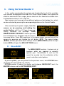
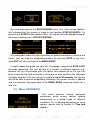
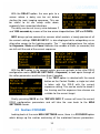
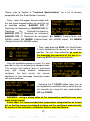
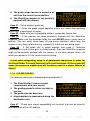
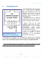
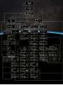
1
TABLE OF CONTENTS
1.
Item Checklist...........................................................................3
2.
Quick Start Guide.....................................................................3
3.
Using the SmartGuider 2 .........................................................4
4.
5.
3.1
Menu BASIC .......................................................................................................4
3.2
Menu ADVANCED ..............................................................................................7
MGA Unit ..................................................................................9
4.1
Section: REFLEX ...............................................................................................9
4.2
Section: FOCUSER..........................................................................................11
Tips and Tricks.......................................................................13
5.1
Error and Warning Messages .........................................................................14
5.2
How to choose a guide scope ........................................................................17
5.3
How to choose a guide star ............................................................................17
5.4
Mount Calibration ............................................................................................18
5.5
How to set AGGRESSIVENESS and PULSE GUIDE......................................19
5.6
DITHERING .......................................................................................................20
6.
Technical Specifications .......................................................21
7.
Autoguider port......................................................................22
8.
Optional Accessories.............................................................23
2
1. Item Checklist
Thank you for purchasing the LVI SmartGuider autoguiding camera!
Upon receipt, please check that your package is complete and contains the
following items:
1.
2.
3.
4.
5.
6.
7.
8.
Control hand paddle (“Control Paddle”).
SmartGuider Camera Head.
MGA Unit.
One SmartEye parfocal eyepiece.
One power supply cable.
Two 8-pin RJ cables, 1 meter and 2 meters in length respectively.
One 6-pin RJ cable (Control paddle to mount’s ST-4 port).
One User’s Manual.
2. Quick Start Guide
Thanks to its ease of use, you can hook up your SmartGuider and be ready
within minutes. Once your imaging rig has been set up, polar aligned and
carefully balanced, here are the main steps to follow:
1.
2.
3.
4.
5.
6.
7.
Make all the necessary connections:
a. Connect the Control Paddle to the MGA and the Camera Head to
the MGA with the two RJ45 8-pin cables.
b. Connect the MGA to the mount’s autoguiding port using the RJ11
6-pin cable.
c. Connect the Control Paddle to a 12V DC power supply.
Look for an adequate guide star and focus it through the enclosed
SmartEye eyepiece.
Replace the eyepiece with the camera head and tighten the screws.
Turn the LVI SmartGuider 2 on.
Press OK, then BASIC and FOCUS to launch STAR SEARCH.
Calibrate the mount.
Start autoguiding.
3
3. Using the SmartGuider 2
In this section we describe the content and functionality for all of the available
user screens as displayed in the wide LCD of the Control Paddle. For a quick and
effective overview of their usage, please check out the flowchart available from
the download section of LVI’s web site.
Most screens can have up to three different options on their bottom line, which
can be activated by pressing the corresponding button on the Control Paddle.
After connecting the power supply, turn the
camera on by pressing and holding the
central button until the LVI logo shows up.
Shortly thereafter, the message “YOUR
SMARTGUIDER 2 IS READY” informs you that
the startup phase is complete and the camera
has come online. Press OK to continue. In the above screen, you can turn off the
camera by pressing and holding the left button (OFF). The central button
(BASIC) will take you to the basic settings screen (MENU BASIC) while the right
button (MGA) will open the MGA SETTINGS menu.
3.1 Menu BASIC
The MENU BASIC contains the basic set of
functions which are required to correctly
operate your SmartGuider 2, such as the
search for a guide star, the calibration of the
mount, and other useful options.
By pressing EXIT, you can go back to the previous menu, while FOCUS takes
you to the next step (guide star search).
OPTION enables to adjust the display and keyboard BACKLIGHT level, the
BUZZER volume and the AUTOGUIDING PORT.
4
You can adjust both the brightness and the buzzer volume with the two
triangular keys on the control paddle: four levels are available, from 1 (minimum)
to 4 (maximum). EXIT takes you back to the basic settings screen.
By choosing THRESHOLD, you can access
the sensor noise level adjustment menu. This
prevents any hot pixels from being mistaken as
stars when the SmartGuider 2 looks for a star
(STAR SEARCH). If your camera detects a
star about 3 pixel wide when the telescope is
capped, slightly increase the value (140) till the fake star is no longer detected.
Selecting GUIDING PORT, brings up the
autoguider interface menu. Four options are
available: ST4, ONE AXIS, AUTOSTAR and
LOSMANDY. ST4 works for all the mounts
with the classical ST4-like autoguider port.
ONE AXIS works with astro-trackers allowing
corrections in one axis only. AUTOSTAR is only valid for Meade LXD55/75
mounts and LX90 telescopes. LOSMANDY is only valid for Digital Drive #492
non-goto (NO Gemini!) motor drives. EXIT takes you back to the MENU BASIC.
Now let us have a closer look at the focusing procedure. Before mounting the
camera onto the guide scope’s drawtube, you have first to center the brightest
star in the field of view which is closest to your imaging target with a wide-field,
low-power eyepiece; then, use the special SmartEye eyepiece to focus the guide
scope and fine tune the position of the star chosen. This eyepiece will deliver a
perfectly focused and centered star in the camera head field of view.
When you press on FOCUS, the SmartGuider 2 scans the whole frame to look
for the previously selected guide star. After a while (the actual duration of the
search phase may vary), the SmartGuider 2 will inform you of the outcome with a
simple message: “STAR FOUND!” or “STAR NOT FOUND!”
5
If the guide star was not found (bottom right), the SmartGuider 2 goes
automatically back to the MENU BASIC screen: in this case a brighter star has to
be chosen. If the star has been found, you can proceed to the next step.
In this screen, the X and Y OFFSET (1 offset unit = 4 sensor pixels) denote the
position of the guide star relative to the detector center, and the small cross in the
rectangular box (see above) indicates the star’s approximate location in a
graphical form.
If the star happens to be lying too close to the sensor boundaries (Offset
limits: X = ±82, Y = ±46), you may want to move it toward the center by
CAREFULLY nudging the mount with the drive keypad at guiding rate.
If the star is thrown off the active area, it will be lost (STAR LOST!
message pops up) and you will have to start over with focusing.
Two focusing aids are available: the FOCUS STAR index and the circle on the
right-hand side of the screen: they both show the diameter of the star (in pixels)
on the detector in numerical and graphical form respectively. Therefore, the lower
the number, the better the focus: a properly focused star should be 3 to 8 pixels
wide according to the brightness and air turbulence.
Once the guide star has been correctly
centered and focused, we can select CALIBR
to get to the calibration screen: press OK to
start calibrating the mount.
The calibration process can last up to a few
minutes. Upon completion, the new calibration
parameters are automatically stored into the camera’s non-volatile memory (the
SAVE icon showed here on the bottom left). In case you want to reuse the
parameters from last calibration, just choose LOAD from the focusing menu
(screen on the lower right). Please see note on calibration on page 18.
6
You have now come to the AUTOGUIDING menu. The initial screen (bottomleft) indicated that the camera is ready to start guiding (STATUS READY). On
pressing the START button (bottom-right), the camera will start compensating all
the mount tracking errors (STATUS GUIDING).
The two graphs allow real-time monitoring of guiding corrections issued to the
mount. You can stop the autoguiding process by pressing STOP at any time,
while EXIT will take you back to the MENU BASIC.
It might happen the guide star gets lost (1 beep per second and STAR LOST
message appearing): this can be due to a number of different reasons, e.g.
because the sky has clouded over, the optics have dewed up, or the star has
been thrown off the field of view by a wind gust or even because the telescope
has been touched. If the star remains invisible for up to 30 seconds, the camera
will still be able to resume autoguiding; otherwise, the current session is aborted
and the execution flow goes back to the MENU BASIC screen to search for a
new star.
3.2 Menu ADVANCED
This menu contains several advanced
parameters which ensure optimal guiding
performance in a broad range of different
conditions. For a detailed description of these
options, please refer to Section 5 (“Tips and
tricks”).
7
EXIT will take us back to the previous menu (STATUS READY), while by
choosing AGGRESS X with the central button we get to the two following
screens:
With the two arrow-shaped buttons (UP and DOWN) on the camera pad, you
can adjust the aggressiveness along the X axis (upper left screen) and along the
Y axis (upper right screen) of the detector.
By choosing PULSE, we get to the screen
where we can set the length of the guiding
corrections the SmartGuider 2 sends to the
mount. These corrections are sent as pulses of
given duration (in milliseconds) which can be
adjusted via the two arrow-shaped buttons.
MAX EXPO brings up the menu where the
user can set the maximum length (in seconds)
of the exposure time used by the camera to
perform the initial search for a guide star.
Higher values will result in higher sensitivity,
but will also increase the duration of the guide
search process (STAR SEARCH).
Next, with DITHER we get to the DITHERING
menu. If turned on (YES), the SmartGuider 2
will apply a very small displacement to the
field of view along both axes after each
exposure taken with the reflex camera
controlled by the MGA. With dithering off (NO
in the menu), the guide star will always be staying in the same position where it
originally was when autoguiding started.
8
4.
MGA Unit
The MGA (Multi Guiding Adapter) is the
interface that allows total control of reflex
cameras, motorized focusers and Meade
LXD55/75 mounts that are compatible with the
SmartGuider 2 camera. For a list of compatible
devices, please refer to Section 6 (“Technical
Specifications”).
To go back to the MENU BASIC screen, we can choose the leftmost option
(EXIT). By pressing the central key (REFLEX) we go to the Reflex management
menu, whereas with FOCUSER we access the motorized focuser control section.
4.1 Section: REFLEX
The REFLEX option from the MGA settings
screen takes us to the section where we can
set the length of the individual exposures of
the main shooting sequence.
By the use of the two arrow-shaped buttons
(UP and DOWN), the exposure time can be
set to anything between 1 and 5000 seconds.
Then we have the BRACKETING menu. This
feature allows to set up an additional imaging
sequence, whose exposure time is calculated
by applying the stop-down setting to the main
sequence’s value. The stop-down can take four
values: OFF (bracketing off), -1 (-1 stop, i.e.
secondary exposure time ½ the main one), -2 (-2 stops or ¼ of the main
exposure), and -3 (-3 stops or ⅛ of the main exposure); these values can be
changed by pressing the two arrow-shaped buttons. So, for example, if the
exposure time is 800 seconds for the main sequence, then the secondary one
will be taking values of either 400 seconds (if set to -1) or 200 seconds (-2) or
100 seconds (-3 stops). The number of exposures for the secondary sequence is
the same as that for the main one.
9
By pressing the central button, we get to the
SHOTS screen, where the user can set the
number of exposures for the main sequence
(and for the secondary one, if active). With the
two arrow buttons (UP/DOWN) any value
between 1 and 1000 can be selected.
PAUSE brings up a screen where the pause
(in seconds) between two consecutive shots
can be adjusted; this interval is useful
especially to allow the camera detector and
electronics to cool down. The two arrows will
let us to choose any value in the range 1 to 100
seconds.
In the MIRROR menu, the camera mirror
lockup can be enabled. If this feature is on, the
mirror will be swung up before the exposure is
made: this prevents mirror-induced microvibrations which might blur the image. Toggle
between ON (lockup enabled) and OFF (lockup
disabled) with the two arrow-shaped buttons.
IMPORTANT WARNING: Mirror lockup is suitable for DSLR cameras
allowing the mirror raising. The same setting (either ON or OFF) MUST be
applied both to the SmartGuider 2 AND the Reflex at the same time,
otherwise erratic behavior may result.
Next, choosing DARK FRAME opens the
dark frame configuration screen. Dark frames
will have to be subtracted from raw shots
during the post-processing phase: this helps in
cutting down thermal noise which is present
especially in long-exposure images. With the
two arrow buttons, we can select from 1 up to 10 dark frames, whose exposure
length will be the same as that of the main sequence.
10
With the DELAY option, the user gets to a
screen where a delay can be set before
starting the main imaging sequence. This can
be useful to let our setup settle down,
especially from unwanted vibrations.
The delay can be set to any value between 1
and 1000 seconds by means of the two arrow-shaped buttons (UP and DOWN).
INFO brings up two consecutive screens which contain a handy preview of all
the current settings. REFLEX INFO 1 is also displayed while autoguiding as an
alternative screen to the tracking graphs. The “-“ sign displayed near the values
for Exposure, Shots and Pause indicates the number of shots (or seconds) that
are left until the end of the current sequence.
With the SET option in the second screen, one can go back to the initial DSLR
configuration menu (REFLEX SETTINGS – Exposure) to look again through all
the reflex parameters and fine tune them if needed.
If the TEST option is selected with the round
button on the Control Paddle, a single test shot
is taken with the DSLR with the current
exposure setting. This can be useful to check if
the framing and the exposure time chosen are
suitable for the current target.
Finally, pressing SAVE on the “REFLEX INFO 2” screen will save the current
DSLR configuration parameters and will take the user back to the MGA
SETTINGS screen.
4.2 Section: FOCUSER
Looking back at the main MGA SETTINGS menu, there is a FOCUSER option
which brings up the section containing all the motorized focuser parameters.
11
Please refer to Section 6 “Technical Specifications” for a list of devices
compatible with the SmartGuider 2 camera.
Firstly, select the proper focuser model with
the two arrow-shaped buttons to scroll the list
of available options: BAADER NT2 (2”
Steeltrack for Newtonians), BAADER SC2 (2”
Steeltrack
for
Schmidt-Cassegrains),
BAADER RT2 (2” Steeltrack for refractors),
BAADER RT3 (3” Steeltrack for refractors), S.I. MSM20 (FeatherTouch with
MSM20 motor), S.I. MSM30 (FeatherTouch with MSM30 motor), S.I. MSM35
(FeatherTouch with MSM35 motor).
Then, upon pressing SAVE, the SmartGuider
2 starts calibrating the focuser to find its zero
position. You can stop calibration as soon as
the drawtube has traveled all the way in by
choosing STOP with the central button.
Once the calibration process is over, it is also
possible to turn on temperature compensation.
This ensures that optimal focus is preserved
even with strong ambient temperature
variations. For best results, the thermal
coefficient of your telescope should be known
with great precision.
Selecting the T COEFF option takes you to
the temperature coefficient menu, which can be
set manually by using the two arrow buttons
(UP and DOWN).
WARNING: using a wrong value of the temperature coefficient can even
make things worse!
In this case, it is recommended that temperature compensation be turned
off, or that the camera be allowed to figure out the coefficient automatically
by means of the automatic calibration routine described below.
12
Upon pressing SAVE, the user is presented with an overview screen showing
the current absolute focuser position, the ambient temperature, the thermal
coefficient value and the thermal compensation status (on/off). By using the two
arrow-shaped buttons (UP and DOWN), the focuser can be moved in or out.
By choosing TEST with the middle button, a
new screen is open with three different options.
From left to right: CALIBR goes to the thermal
coefficient calibration screen, SHOOT takes a
test shot (when pressing and holding down the
central button, the DSLR shutter stays open
until the button is released), and EXIT goes out of the FOCUSER section back to
the MGA SETTINGS menu.
CALIBR brings up the screen on the right,
where the user can start the self-learning
procedure of the thermal coefficient by pushing
LEARN with the central button. EXIT jumps
back to the MGA SETTINGS main menu.
The coefficient learning strictly requires the
thermo probe supplied with the focuser and the
OTA temperature must vary at least by 0.5
°C (best if 1 C or more) in order to properly
learn the coefficient. The SmartGuider 2 will
disable the STOP button until a 0.5 C difference is reached. When the STOP
button is enabled on the left side, you can push it to store the coefficient into the
SmartGuider 2’s permanent memory.
Press the TEST central button to take a focus-testing shot with your Reflex
camera.
5.
Tips and Tricks
The SmartGuider 2 is simple and intuitive to use.
However, as with any setup, when taking long-exposure astronomical images
you may be faced with problems in autoguiding. The following are some
messages which could show up during the setup phase or while autoguiding. For
further information, please don’t hesitate to contact LVI.
13
5.1 Error and Warning Messages
1.1.1 STAR LOST!
This message is accompanied by an audible signal until the star becomes
visible again. It is displayed only during autoguiding and may occur if:
1.
2.
3.
4.
5.
The sky has clouded over.
The guide scope lens has dewed up.
The guiding speed is too high.
The telescope was hit.
Strained cables.
Cases #1, #2 - The SmartGuider can no longer find the guide star and starts
beeping every second, for up to 30 seconds, until the star becomes visible again;
otherwise, autoguiding is aborted.
Case #3 - The mount guiding speed is too high and the guide star keeps
wobbling in the field of view, so the camera has trouble tracking it. In this case,
the guiding speed should be lowered through the mount control box. Typical
suggested values are between 0.125x (12.5% of the sidereal rate) and 0.50x
(50% of the sidereal rate).
Cases #4, #5 - If the telescope gets hit or the cables strained, the SmartGuider
2 camera can lose the star temporarily or permanently, depending how on much
the telescope aim has been thrown off.
During operation, the Control Paddle should be kept firmly in place on a
stable surface, or hung up onto the mount.
Please do NOT touch or leave it in an unstable position!
1.1.2 STAR NOT FOUND!
This message can be displayed after STAR SEARCH and occurs if:
1. The guide star is too faint (See page 21 ‘Technical Specifications’).
2. The guide scope objective has dewed up.
3. The guide scope support and/or focuser are not sturdy enough.
14
4. The guide scope focuser is moved in or
out from the correct focus position.
5. The SmartEye eyepiece is not perfectly
parfocal with the camera.
Case #1 – Pick a brighter guide star.
Case #2 – Clean the guide scope objective and/or use some dew-removing
device (e.g. a dew cap or a heater).
Case #3 - Make sure your autoguiding setup is reasonably flexure-free.
Case #4 – If the camera has been previously focused with the SmartEye
eyepiece, make sure the drawtube holds firm and NEVER move it away from its
position. This can easily throw focus off and cause vibrations: either way, the
camera is very likely to lose the star, especially if a dim one was being used.
Case #5 - If the guide star is bright enough (see page 5 ‘Technical
Specifications’) and all your gear is sturdy enough, then your SmartEye eyepiece
might not be perfectly parfocal with the camera. In this case, please return it to
either your dealer or LVI for service and fine-tuning.
A rock-solid autoguiding setup is of paramount importance in order for
the SmartGuider 2 to work flawlessly with your telescope. A flimsy gear will
cause the camera to wobble and will therefore result in a higher chance of
failure!
1.1.3 CALIBR FAILED!
The following message is displayed during calibration if:
1. The SmartGuider 2 camera cannot
communicate with your mount;
2. The guiding speed is either too high or
too low;
3. The guide star has been lost;
4. Huge backlash is experienced along the
declination axis.
Case #1 - Check your mount compatibility on the chart that can be found in
download area of the LVI website.
15
Case #2 – Carefully take note of when this message is displayed. If this
happens within about a dozen seconds since the start of step 1/6 Moving RA -,
the guiding speed must be lowered with your mount control box.
If it happens after a couple of minutes, the guiding speed must be increased.
Suggested values range from 0.10x (10% of the sidereal rate) up to 0.50x (50%
of the sidereal rate).
Case #3 - See above message “1.1.1 STAR LOST”.
Case #4 – Adjust your mount so as to minimize the backlash between the
worm and the gear. Such an error could pop up during the 3/6 Moving DEC+
calibration step.
1.1.4 COMMUNICATION ERROR!
The following message is displayed if the
cable connecting the Control Paddle and the
camera head is accidentally disconnected, or in
case it’s too long or faulty. This message could
as well be displayed also if your camera is
faulty. In this occurrence, please contact your
vendor or LVI to return the camera for service.
1.1.5 HOT PIXEL DETECTION
If a “star” about 3 pixels across unexpectedly
appears quite far off the sensor center, most
likely it is a hot pixel. This happens most often
in summer, when high temperatures can
randomly turn hot pixels on, especially if the
camera has been in use for quite a long time.
To make sure about the nature of this “star”, power off the camera for a while and
then turn it back on with the nosepiece tightly capped. This operation can be
performed also at daytime in a dark environment. Run STAR SEARCH in this
condition, and if the STAR FOUND! message is displayed, go to the OPTION
menu and then to NOISE THRESHOLD. Turn up the threshold to values higher
than 140 until the camera no longer detects fake “stars”.
16
5.2 How to choose a guide scope
Thanks to its sub-pixel guiding capability, the SmartGuider 2 does not call for
telescopes with very long focal length or particularly wide aperture. As a rule of
thumb, when imaging with DSLRs or CCDs (pixel size between 5 and 8 microns),
the guide scope should have no less than the half of the focal length as that of
the main instrument. In any case, it is advisable to use refractors instead of slow
catadioptric reflectors (e.g. Maksutov with f/ratio of 10 and higher), since focusing
by movable primary mirror can easily lead to exposure trailing even if the tracking
performance looks apparently good. Moreover, there are cases where high
magnification is not always an advantage, due to lower brightness and increased
sensitivity to atmospheric turbulence (seeing).
5.3 How to choose a guide star
Your equipment must not be touched during the STAR SEARCH
operation, otherwise the star could not be detected correctly. This also
applies to the Control Paddle which must not be held in your hands!
The limiting magnitude reached by SmartGuider 2 is about 9 with an 80mm
aperture scope. Such a limit is valid under very dark and still skies and may be
lower under less-than-ideal visibility conditions, and/or MAX EXPOSURE is not
set to 4 and/or your guiding scope has a smaller aperture. Guide stars should
always be chosen taking all these factors into account.
The SmartGuider 2 camera automatically looks for the star that was previously
centered and focused via the supplied SmartEye eyepiece. A partial scan of the
sensor is performed with the exposure set in MAX EXPOSURE function, so the
actual duration of the search phase is rather variable. As a rule of thumb, the
higher the MAX EXPOSURE, the deeper the limiting magnitude, but the longer it
takes to locate a star.
When a star has been found, the SmartGuider 2 automatically adjusts the
exposure according to the star’s brightness. The lengths of the exposure directly
affects the frequency of corrections sent to the mount: bright stars do allow for
continuous position control, which also ensures that all sorts of tracking errors,
including the component resulting from periodic error and atmospheric
17
turbulence, will be easily guided out. Bright stars are best to compensate for the
most erratic periodic errors, or with guide scopes having a focal length shorter
than that of the main optics. In this case, we advise using a moderate guiding
speed (0.15 - 0.5X) with HIGH aggressiveness (see detailed explanation below).
On the other hand, fainter stars imply a less frequent correction of tracking
errors: this makes them not as suitable for mounts with an irregular periodic error.
However, long exposure times required by faint stars could come in handy to
minimize the influence of bad seeing. Here we suggest a very low guiding speed,
best if no higher than 0.25X with MILD aggressiveness.
When the search for the guide star fails, you can push the MAX EXPOSURE to
4 seconds and try again. If, in spite of that, the camera does not manage to find a
star, then mount your guide scope on a pair of rings and orient it slightly off-axis
until you find a suitable star. In case an off-axis guider is being used, the pick-off
prism and tube can be moved and/or rotated to find a brighter star.
If your camera still fails to detect a guide star, you may want to recheck the
quality of focusing.
If you wear glasses, those must be kept always on, also when focusing
with the SmartEye eyepiece!
When the atmosphere is very unstable (poor seeing) and stars are twinkling
fast, a slight defocus can help in mitigating scintillation. This will result in a
smoother autoguiding.
5.4 Mount Calibration
Once calibration is over, the parameters are permanently stored into the
SmartGuider 2 internal memory for later use, provided that the following
precautions are taken into account:
1. Always guide on stars lying in the same side of the sky (with respect
to the local meridian) where the calibration was last performed;
2. NEVER take the camera off the guide scope;
3. NEVER rotate the camera in the guide scope focuser.
18
In all other cases, the camera must always be recalibrated.
The telescope must not be touched during calibration, otherwise the
relevant parameters could not be calculated correctly. This also applies to
the Control Paddle unit which must not stay in your hand!
It might take a relatively long time for the calibration process to complete,
especially with guide scopes of short focal length (under 500 mm) and slow
guiding rates (0.25X or slower).
When the autoguiding mode is set to ONE AXIS, the SmartGuider 2 loads a
special parameter which requires the camera head to be oriented so that the
longer edge of the sensor is parallel to the right ascension (RA) axis.
Calibration is not available with this option.
5.5 How to set AGGRESSIVENESS and PULSE GUIDE
Both autoguiding graphs must be smooth and regular. To make
successful use of your SmartGuider 2 from the very beginning, it is
advisable to start off with default parameter values and set the lowest
guiding rate for your mount.
The AGGRESSIVENESS parameter defines the “reaction threshold” (in terms
of sensor pixels), i.e. the value of the offset between two consecutive exposure
cycles above which the camera will make a correction. The lower the
aggressiveness, the higher the tracking error allowed and vice-versa.
HIGH values are suitable when using small refractors featuring a focal length
1,5-2 times smaller than the main instrument. MILD values are for guide scopes
of about the same focal length and LOW ones are best in case of very long guide
scopes or off axis guiding (typically SCTs).
Default values (5 for both axes, X and Y) are generally suitable for a wide range
of cases and should be varied only if necessary (for example, in case of
unsatisfactory guiding accuracy).
The PULSE GUIDE parameter sets the duration for the individual corrections
sent to the mount. As a rule of thumb, the better the tracking precision of the
mount, the lower the value.
19
The default value (250 msec) has been chosen to ensure optimal results with
most mounts currently available on the market. First-class models (e.g. 10Micron,
Astrophysics, Paramount, etc) with low (within ± 5 arcsec) and smooth periodic
error and extremely low gear backlash all require a value in the 25-50 msec
range.
If you notice any significant oscillations across the zero line in one or both
graphs (overcorrection), the guiding rate should be decreased with the mount
drive keypad until the oscillation decreases (ideally, until it becomes almost
negligible). If the oscillation still persists, decrease the AGGRESSIVENESS or
the PULSE GUIDE duration, or both.
In case the profile of one or both graphs keeps steadily above or below the zero
value (undercorrection), the guiding rate must be gradually increased until the
graph profile goes back to hovering around the zero position. If no improvement
is noticed, the AGGRESSIVENESS or the PULSE GUIDE or both have to be
increased.
Should the graphs still be showing a small, jerky oscillation in spite of the above
precautions, please make sure your equipment is properly balanced in both axes.
It must be stressed that a perfect balance of all the weights, the quality
and solidity of all the mechanical supports and adapters is of utmost
importance in getting round stars! Sometimes, trailing due to differential
flexure can ruin your pictures even with apparently smooth tracking.
5.6 DITHERING
With ideally perfect autoguiding, the field of view and the target will always stay
in the same position throughout all the exposures; unfortunately, so will hot
pixels. Therefore, they will be very difficult to filter out during post-processing.
That’s where the DITHERING function comes in handy. When it is activated
(ON), the telescope is shifted slightly between exposures to offset each image
slightly. This results in fixed pixel defects being misaligned in the final composite
image: thus it will be much easier for image combine methods such as median or
Sigma Clip to remove them.
20
6.
Technical Specifications
CAMERA HEAD
Sensor.............................................................................Mono 1/3" Aptina MT9V032
Sensor array…......................................................752x480 pixel, 6-µm square pixels
Exposure time range...............................................................Auto, 0.01 - 4 seconds
Limiting magnitude (Scope with D=80mm)…..............................................about 9.0
Dimensions and weight........................................D=65mm, H=50mm, Weight: 110g
CONTROL PADDLE
Keypad.................................................Three membrane keys with back-illumination
Display..................................2.5-inch graphical backlit LCD, 128x64 pixel resolution
Dimensions and weight.....................................LxHxW: 55x96x28mm, Weight: 220g
Voltage and consumption...............................................................6-14V DC, 110mA
MGA UNIT
Power supply................................ 3xAA alkaline batteries (FOCUSER section only)
Controlled Mount.....................................Any, including Meade LXD55/75 and LX90
Controlled Reflex........................................Canon EOS, Nikon D, Pentax (ist and K)
Sony a, Minolta Dimage, Fujifilm S
Controlled Focuser…………...…… Baader Steeltrack (1), Starlight FeatherTouch (2)
Dimensions and weight.................................LxWxH: 118x102x33mm, Weight: 125g
1
( ) Requires the optional Steeldrive motor to be purchased apart.
(2) Requires the optional MSM motor with dedicated adapter to be purchased apart.
FEATURES
- Automatic guide star search.
- Automatic axes calibration with permanent saving.
- Adjustable noise threshold level.
- Real-time monitoring of any technical information.
- Adjustable display backlight and buzzer volume.
- Dithering to get rid of cosmetic defects in DSLR images.
- Adjustable aggressiveness and pulse duration for maximum guiding performances.
- High-precision 2X sub-pixel autoguiding.
- Advanced Control with Reflex, Focusers and Meade LXD mounts.
21
7.
Autoguider port
The SmartGuider 2 camera comes
with an “open collector” autoguiding
port, fully compliant with the ST4
standard. This means it can be
plugged straight into all most popular
equatorial mounts having such an
autoguiding port.
The MGA unit features an optically
isolated port that can work with any
mount, Losmandy models included.
However, there can be some
exceptions: plugs other than RJ11,
different pinout, or even electrical
incompatibility
could
cause
communication problems between
the mount and the camera.
In this case, an optional cable or
adapter is required to ensure
compatibility of the SmartGuider
camera with such mounts.
Pinout diagram of the RJ11
SmartGuider 2 autoguiding port
A detailed chart is available in the “Download Area” section of the LVI website
which shows the compatibility of the camera towards a broad selection of popular
mounts, and a list of optional add-ons that are necessary for proper operation.
If this manual didn’t help solve your problems, LVI technical support will be glad
to give you a timely assistance in getting rid of any kind of malfunction!
22
8.
Optional Accessories
Find here below a list of optional accessories to plug the SmartGuider 2 camera
to a variety of Focusers, DSLRs and mounts. Visit LVI website for further details.
REFLEX Section
Cable LVI-REF-Can1, L=2m
Cable LVI-REF-Can2, L=2m
Cable LVI-REF-Nikon L=2m
Cable LVI-REF-Sony L=2m
FOCUSER Section
Cable LVI-FOC, L=2m
MOUNT Section
Cable LVI-LXD, L=2m
LVI-TAK Adapter
Cable LVI-LX, L=2m
LVI-VIX Adapter
23
24