1
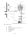
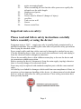
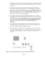
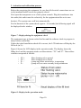
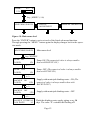
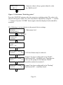
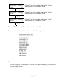
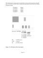
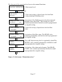
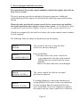
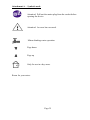
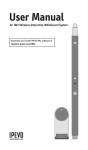
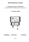
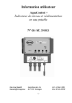
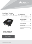
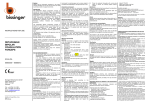
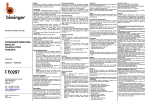
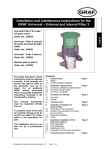
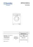
User Manual
AquaControl +
Rainwater System Controller
Item no.: 351027
Otto Graf GmbH
Kunststofferzeugnisse
Carl-Zeiss-Str. 2-6
D-79 331 Teningen
Page 1
Tel .: +49(0)7641-5890
Fax: +49(0)7641-58950
Figure 1: View of equipment
1:
2:
3:
4:
5:
6:
7:
LED for power supply
Information Display
LED for drinking water operation
LED for faults and malfunction
Operating buttons
Lower cover of the System Control
The main fuse for the rainwater system controller is under this
cover.
Page 2
Figure 2: Sensor assembly
12:
13:
14:
15:
16:
17:
18:
19:
Data cable
Wire seal 3
Connection of the data cable is polarity protected.
connect white wire here
connect red wire here
data cable terminal
Wire seal 2
Wire seal 1
Page 3
20:
21:
22:
23:
24:
25:
26:
27:
28:
active measuring length
When assembling be sure that the cable spacers are equally distributed over the cable length.
Stainless steel probe
Tank floor
Screws must be blunted ! (danger of injury)
overflow
Tank or riser wall
Sensor
Sensor control box
Important notes on safety:
Please read and follow safety instructions carefully
before assembly or using the device!
Equipment using a 120 V ~ supply may only be installed and commissioned by a
qualified tradesman. The assembly place must allow all possible safety precautions
when laying the attached cables.
Power supply cables and data cables mast not be damaged or pinched in any way.
Plan the assembly place so that you can reach the transformer easily and unplug it
from the electrical outlet in dangerous situations.
Choose the assembly place so that children cannot play or be near the device and
its connections without supervision.
Before opening the device, disconnect it from the main supply (unplug) otherwise
there is a serious danger of an electrical shock.
Fuses may only be replaced with standard-compliant parts with the same nominal
value.
All liability is excluded for damages which result from non-compliance of these instructions or from improper handling of the device. At chosen intervals in this hand
book we will give directions for safety precautions. These safety precautions have
been specially marked:
Page 4
1. Description
The AquaControl+ is an electronic water management control system.
It has been developed especially for rainwater usage systems. It can be used with a
wide variety of tank systems.
Tanks made from metal or steel reinforced cement may only be used when the following conditions have been correctly followed.
Metal tanks lead to faulty readings. It is optimal to install the device so that the
sensor is as far as possible from the metal sides so, for example, in the center of a
cylindrical tank. The system controls offer an easy to use guide for the switch programming. Using an LCD display the fill measurement is shown in 1 % stages (in
relation to the height of the tank).The sensor operates with 12 volts DC, supplied
from the main control unit.
All programmed values such as the tank height are retained after disconnection
of the power supply or after loss of power.
Performance features:
–
–
–
–
–
–
–
–
Fill level measurement display in 1% steps with a bar type indicator
Freely variable switching points in 1% steps for drinking water refill
Automatic flushing of the system intervals in days, and duration in
minutes are programmable
Dialogue oriented user guidance (choice of language)
Equipment indication using 3 additional LED
Supervision of the sensor control box and the sensor
Error indications in simple text
Analog output for connection to external systems: 0-10V DC
Technical data:
Control electronics
Operating current
Fused
Power consumption
Tank height
Measurements
Measurement sensors
:24VAC
:T500mA
:3VA
Measurement voltage :12V DC
Measuring frequency :(0.2-20)kHz
Data cable length
:165 feet,
maximum
:9.8 feet (optional 20feet)
:6.1”x6.5”x3.5” Measurements
:3.6”x3.2”x2”
Page 5
Terminal 1
Operating voltage
Maximum Current
Terminal 2-4
: 24V AC
: 5Amps
Operating voltage
Maximum Current
: 24V AC
: 1Amps
Terminal 5
Operating voltage
Maximum Current
: 120V AC/DC
: 3Amps
Analogue outlet:
Minimal apparent ohmic resistance
Short circuit protection
Short circuit current
Cable length
: 20K Ohm
: Yes
: Approx 15mA
: 650 feet, maximum ; shielded
Note:
Only the control electronics in the device are protected by the fuse. Valves and
pump connections are not protected. These are protected only by the mains supply
via the circuit breaker.
The yellow LED indicating “Drinking water operation”[3] is lit as soon as the
valve switches over to the mains supply. The user is made aware that the system
now uses water from the mains supply. The red LED for “Faults and
malfunctions” [4] is lit as soon as the system identifies a fault. The display will
then show a warning that describes the cause of the fault in plain text.
2. Assembly
2.1 Control system
The mains plug of the transformer serves as an on / off switch.
–
–
Loosen the fastening screws of the lower cover [6] and remove the cover
Mark out drilling points and drill according to sketch
Page 6
–
Fasten the device with the enclosed installation hardware (screw anchor and
screws)
Figure 3: Drilling outline for housing outline
2 .2 Connection sensors and data cable:
The sensor electronics comprise of a stainless steel probe [22] with red and white
connecting wires [27] and the sensor control box [28].
Figure 4: Sensor technology
1.
Now the sensor control box [28] (cover removed) should be installed on
the tank wall (preferably in the man hole shaft of the Graf synthetic tank).
The location of the mounted sensor control box should be between 4” and
6” above the overflow [25]. The enclosed screws should be used to secure
the device. After fully tightening the screws, the points that are showing
themselves on the outside of the tank must be blunted to avoid injury [24].
2. Measure the height from the bottom of the tank [23] to the end of the
terminals [15] and [16] on the [28].
3. Shorten the connection cable to suit the measured height.
4. After shortening the cable, the distance between the cable fastening
spacers [21] should be set equally along the entire length. The cable
fastening spacers prevent the red and white wires of the sensor from
crossing over and thereby causing a slight distortion of the measurement
Page 7
readings. If for any reason the cable fastening spacers cannot be mounted,
an additional distortion of the measurement reading of approximately 1%
may result.
5. Connect the sensor cable to the sensor as described in the following
instructions: Remove approximately 1/4" of insulation from both of the
wires. Next, pass the red wire through the wire seal 1[19] and tighten this
lightly, then connect the red wire to the terminal [16]. The free white wire
is now passed through the wire seal 2 [18] and tightened lightly, then
connect the white wire to the terminal [15].
6.
Now pass the end of the data cable [12] through the wire seal 3 [13].
Lightly tighten the wire seal and connect the cable wire cores of the data
cable [12] to the double terminal [14]. The connection of the data cable is
reverse polarity protected. Attention! The screws should be tightened
with care to ensure that they are not damaged through over
tightening.
7.
Now recheck that all the connections and the sensor components have
been fitted correctly. Replace the cover of the sensor control box and
secure this with the appropriate fastening screws.
8.
At the main system control unit, remove the jacket from the ends of the
sensor data cables, strip about ¼'' of insulation from the wires, and insert
each wire into the appropriate terminal . Tighten the terminal screws
securely.
Figure 5: Connection of the sensor system at the System Control
Page 8
Note:
The red and the white wires going down to the probe should be straight and
smooth to be drawn taught by the weight of the stainless steel probe. The stainless
steel probe must hang just above the tank floor. When setting the spacers please be
sure to distribute them equally over the complete length as shown in Figure 2.
2.3. Electrical wiring diagram
The AquaControl+ offers the rain water system a dry run protection for the pump
or the house water system when equipped with an external pump relay. In order for
the dry run protection will function properly the rain water system must be wired
according to the following diagram.
Fuse 500mA
1: Terminal 1
2: Terminal 2
3: Terminal 3
4: Terminal 4
NO,COM,NC: Terminal 5
G: Ground (grounding conductor)
24V/60Hz: Input 24V/AC
P: Input 24V/AC
For the supply of 24V AC to operate valves and other accessories, external power
must be supplied to the 24V AC input terminals using a transformer sufficient for
the needs of the attached devices.
Figure 6: electrical wiring diagram
Page 9
3. Activation and calibration process
Before the energizing the equipment, be sure that all electrical connections are correctly insulated and all covers are properly closed.
Now open the transparent cover of the system controls. Plug the transformer into
the outlet (this outlet must be exclusively for the equipment and be on its own
breaker). The system runs a self-test automatically.
For the duration of the system check (approx. 10 seconds) the following signal will
be displayed in the window:
AQ +
REV U2.0
Figure 7: Display during the equipment check
The equipment type is shown on the first line and the software check in progress is
shown in the second line.
If after the initial installation check all is correct, the LCD indicator will display the
fill level (in %).
Figure 8 shows the LCD-display in the operation mode. The display shows the
filling level and the operating modes as abbreviations: "FV" and "P". These abbreviations correspond as follows:
–
–
–
–
FV+ :
FV- :
P+ :
P- :
filter cleaning valve opened
filter cleaning valve closed
(pump on) house waterworks in operation
(pump off) no water currently being withdrawn
Figure 8: Display in the operation mode
Page 10
4. Set up of the system control:
After putting into operation, the system control must be adjusted and programmed
according to the conditions and requirements of the individual user's system. The
required settings are easily programmed. There are four buttons for this purpose.
All necessary programming data entries follow a menu displayed by the LCD. For
the set up, follow all the points listed in table 1 in the sequence shown. Should any
error in the sequence occur then it is necessary to begin the set up again from the
beginning starting with the tank height. Begin the programming of the settings by
pressing the button marked “MENU”.
With the buttons “+” or “-” the menu may be scrolled backwards and forwards.
With the respective menu point shown the values may be altered. For this the
button “ENTER” must be used. The value begins to flash. With the “+” or “-” the
desired value may now be entered according to individual requirements. When the
desired value has been entered this must be confirmed by pressing the “ENTER”
button. The value is only then taken over and stored in the programming of the unit.
Through pressing the “MENU” button again the display changes back to the
operation mode.
It is possible to reset the unit to the factory setting standard values at any time.
The resetting can only be carried out in the operation mode (Display see Figure 7):
To do this press the “ENTER” button and hold it pressed. Now simultaneously in
addition press the “MENU” button. After a short wait the following display will be
shown:
DEFAULT VALUES
23%
Figure 9: Message reset to standard factory settings
As soon as this message is displayed the buttons may be released
The menu structure integrated in the system control is outlined in Figure 9. To
bring up the menu, press and hold the „MENU“ button for longer than 5 seconds.
All outputs are inactive when the menu level has been activated and operation of
the device is suspended. The system automatically returns to operating mode when
no entries have been received for approximately 30 seconds.
Page 11
TANK:
23%
FV- P+
key „MENU“ (>5s)
SWITCHING POINTS
MANUAL OPERATION
DEVICE
ADJUSTMENT
+/-
+/-
Figure 10: Main menu level
Press the “ENTER” button to arrive at each of the listed sub-menu functions.
Through pressing the “MENU” button again the display changes back to the operation mode.
SWITCHING POINTS
Main menu level
key “ENTER“
PUMP ON
0-100%
8%
Pump ON (The numerical value is always smaller
than with BACKUP ON.)
6%
Pump OFF (The numerical value is always smaller
than with PUMP ON.)
+/PUMP
OFF
0-100%
+/BACKUP
ON
0-100%
10%
+/-
BACKUP
OFF
0-100%
12%
Supply with municipal drinking water - ON (The
numerical value is always smaller than with
BACKUP OFF.)
Supply with municipal drinking water - OFF
+/BACKUP INTERVAL
0-14 DAYS
14
Flush the drinking water supply piping every 14
days. The value “0“ switches the flushing off.
Page 12
+/BACKUP
0-60 SEC
30
Flush the drinking water supply pipes for 30
seconds.
+/CLEANER INTERVAL
0-14 DAYS
14
Cleaning the rainwater filter every 14 days
The value 0 switches the cleaning process off.
+/CLEANER DURATION
0-60 SEC
5
Cleaning the rainwater filter for 5 seconds
+/CLEANER RINSE AT
INCREMENT
+/DRAIN DELAY
0 – 60 DAYS
2%
Cleaning the rainwater filter when the fill level
has increased by 2% after rainfall. If the fill level
continues to increase, the rinsing will be repeated
every 3 hours.
Cleaning the drain tank every “x” days.
+/DRAIN TIME
Cleaning the drain tank for “x” minutes.
0 – 60 MIN
+/TRANSFER FROM
0 – 100 %
+/-
REFILL ON
0 – 100 %
+/-
This enables water to be pumped out of the main
tank. The chosen numeric value “Transfer from”
should always be greater than the numeric
value “BACKUP OFF”!
The water will be pumped off when it rises above
the set value. To prevent constant switching on
and off of this function, it is pumped off to 2%
under the opposed value.
Numeric value is always greater than the value
“BACKUP ON” and less than the value for
“REFILL OFF”.
Page 13
Numeric value is always greater than the value
for “REFILL ON”.
REFILL OFF
0 – 100 %
+/-
Figure 11: Sub-menu “Switching points”
Press the “ENTER“ button to alter the respective switching points The value to be
altered will begin to blink. The value may then be adjusted by using the “+“ and the
“-“ buttons. Press the “ENTER” button again when the displayed value should be
accepted.
The following is an introduction to the general device settings:
DEVICE
ADJUSTMENT
Main menu level
key “ENTER“
LANGUAGE
ENGLISH
+/UNITS
INCH / CM
+/MEASURING LENGTH
30-600cm
200
+/OPERATION
REFILL
TERM. 1
NO
+/OPERATION
BACKUP
TERM. 2
NC
(A 20 feet Sensor may be ordered.)
Output 1 has been configured for the "Refill"
function and NO = normally open. Therefore the
valve (or the pump) for the function "Refill"
should be attached at terminal 1.
Output 2 has been configured for the "Backup"
function and NC = normally closed.
+/-
Page 14
OPERATION
PUMP
TERM. 3
NO
Output 3 has been configured for the "Pump"
function and NO= normally open.
+/OPERATION
DRAIN
TERM. 4
NO
Output 4 has been configured for the "Drain"
function and NO= normally open.
+/OPERATION
ERROR
TERM. 5
NC
Output 5 has been configured for the "Error"
function and NC= normally closed.
+/Figure 12: Sub-menu “General device description”
For each terminal the selection between the following functions exists:
BOOSTER PUMP NO
BOOSTER PUMP NC
CLEANER NO
CLEANER NC
BACKUP NO
BACKUP NC
TRANSFER NO
TRANSFER NC
REFILL NO
REFILL NC
PUMP NO
PUMP NC
DRAIN NO
DRAIN NC
Note:
Please configure each output according the requirements of your rainwater
system requirements.
Page 15
The function of the output can be specified for each terminal separately (normally
open or normally closed). Please consider the maximum current values for each individual terminal:
Terminal 1:
Terminal 2:
Terminal 3:
Terminal 4:
Terminal 5:
NO
COM
NC
5Amps
1Amps
1Amps
1Amps
3Amps
: normally open
: common
: normally closed
Figure 13: Allocation of the relay outputs
Page 16
The last part of the operation level covers the manual functions:
MANUAL OPERATION
Main menu level
Key “ENTER“
LAST FLUSH
BACKUP
0
+/HAND FLUSH
BACKUP
NO
+/LAST RINSE
CLEANER
1
Time scale in days; elapsed since the last flush
using municipal drinking water
Activation of the flushing process for the municipal
drinking water inlet pipe. The switch-over valve
remains permanently switched on until reprogrammed
to original setting.
Time scale in days; elapsed since the last filter
rinse.
+/HAND RINSE
CLEANER
NO
Activation of the filter rinse. The RINSE valve
remains permanently switched on until reprogrammed
to original setting.
+/The refill function may also be regulated by hand.The
REFILL valve remains permanently switched on until
reprogrammed to original setting.
HAND
REFILL
+/Activation of the drain tank cleaning. The DRAIN
TANK valve remains permanently switched on until
reprogrammed to original setting.
HAND
DRAIN
+/Figure 14: Sub-menu “Manual functions”
Page 17
5. Error messages and fault correction:
The operation of the system control should be checked at regular intervals (at
least every 4 weeks).
The error messages provide an indication of general symptoms. Additional
troubleshooting will be required to determine the underlying cause and necessary
actions.
Please also take note that the system control device cannot sense any malfunction of the municipal water supply or house water system. (No malfunction signal
is supplied by external water supplies or devices to the system control device).
If faults are recognized by the tank level sensor, the system control cannot continue
to work properly.
The following faults are shown in the plain text on the display:
ERROR
SENSOR
ERROR
DL SHORT CIRCUIT
The reason for this error is that the white
sensor wire has been damaged.
Error possibilities:
-The data cable of the sensor control box
is not connected to the data cable terminal
[14] but has been connected to the sensor
terminal
- Wires of the data cable have been damaged
ERROR
SENSOR CONTROL
The sensor control box delivers no signal
and must be replaced.
ERROR
SENSOR SYSTEM
For further diagnosis, remove the stainless steel
weight [22] out of the water. If the error indication
has now stopped, then the sensor itself was the
cause of the fault. If the error indication continues,
this implies that the sensor control box is defective.
Page 18
ERROR
NO SIGNAL
ERROR
MEMORY
Figure 15: Error messages
The communication between the system
control to the sensor control box is
interrupted.
First try re-setting the system control to the
factory default settings . If the error message
continues to be displayed then it is necessary
to contact your service partner.
Note: After resetting to the factory
default settings all the newly
programmed setting values will
have been overwritten and must be
re-programmed!
If the device shows no function at all then check whether the main electrical supply
provides current and also check the house breakers.
If the electrical outlet is working properly, then unplug the transformer from the
system control. Once the system has been de-energized open the lower cover of the
system control (see Figure 1) and check the rainwater system controller main fuse.
6. Analog outlet:Your device has been fitted with an analogue terminal. This terminal shows the percent values from the system control (0% -100%) by a voltage range from 0V to
10V DC. The following connection values apply:
Minimal apparent ohmic resistance
Short circuit protection
Short circuit current
Cable length
: 20K Ohm
: Yes
: Approx 15mA
: 650 feet, maximum; shielded
Page 19
Note:
The system control is only capable of displaying whole percent values (no fractions). These are shown on the analogue signal display.
Figure 16: Allocation of the analogue terminal
Page 20
Attachment A – Symbols used:
Attention! Pull out the mains plug from the socket before
opening the device.
Attention! An error has occurred.
Mains drinking water operation
Page down
Page up
Only for use in a dry areas.
Room for your notes:
Page 21
Page 22
Page 23
Purchase date
Device serial number / Type
Tank height
Software level AQ+ REV
: ...................................
: AS AQ RH.................
: ...................................
: U2.0
Design and specifications are subject to change without notice
Dated: September 2011 ; Version: AQ+ U2.0
Page 24