1
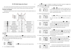
KF-1067 MODEL KF-1067 Ëà µÊ ÷é OPERATOR`S MANUAL COLOR VIDEO SOUNDER SAFETY INSTRUCTIONS WARNING ELECTRICAL SHOCK HAZARD Do not open the equipment. Only qualified personnel should work inside the equipment. Immediately turn off the power at the switchboard if water leaks into the equipment or something is dropped in the equipment. Continued use of the equipment can cause fire or electrical shock. Contact a ONWA agent for service. Do not disassemble or modify the equipment. Fire, electrical shock or serious injury can result. WARNING Make sure no rain or water splash leaks into the equipment. Fire or electrical shock can result if water leaks in the equipment. Keep heater away from equipment. A heater can melt the equipment’s power cord, which can cause fire or electrical shock. Use the proper fuse. Fuse rating is shown on the equipment. Use of a wrong fuse can result in damage to the equipment. Do not place liquid-filled containers on the top of the equipment. Fire or electrical shock can result if a liquid spills into the equipment. Immediately turn off the power at the switchboard if the equipment is emitting smoke or fire. Continued use of the equipment can cause fire or electrical shock. Contact a ONWA agent for service. WARNING TABLE OF CONTENTS INTRODUCTION 2.15 Alarms 2.16 White Marker 2.17 Adjusting TVG PRINCIPLE OF OPERATION SYSTEM CONFIGURATION 1. CONTROLS, INDICATIONS 1.1 Control Description 1.2 Indications 2. BASIC OPERATION 2.1 Turning the Power On/Off 2.2 Adjusting Brilliance 2.3 Display mode Selection, Description 2.4 Adjusting Gain 2.5 Automatic Operation 2.6 Selecting Picture Advance Speed 2.7 Display Range selection 2.8 Erasing Weak Echoes 2.9 Measuring Depth to a Fish School 2.10 A-scope Display 2.11 Menu Operation 2.12 Suppressing interference 2.13 Suppressing Low Level Noise 2.14 Selecting Background and Echo Colors 1-1 1-1 1-4 2-1 2-1 2-1 2-1 2-5 2-5 2-6 2-6 2-7 2-8 2-8 2-9 2-12 2-12 2-13 2-13 2-15 2-15 3. INTERPRETING THE DISPLAY 3.1 Zero Line 3.2 Fish School Echoes 3.3 Bottom Echo 3.4 Surface Noise/Aeration 3-1 3-1 3-1 3-1 3-2 4. MAINTENANCE, TROUBLESHOOTING 4.1 Maintenance 4.2 Basic Troubleshooting 4.3 Transducer Check 4.4 Water Temperature Sensor (option) Check 4-1 4-1 4-3 4-4 MENU TREE A-1 4-4 SPECIFICATIONS SP-1 INDEX Index-1 INTRODUCTION Congratulations on your choice of the ONWA KF-1067 Color Video Sounder. We are confident that you will enjoy many years of operation with this fine piece of equipment. The KF-1067 is just one of the many ONWA developments in the field of echo sounding. The compact, lightweight but rugged unit is easy to install and operate and is suitable for both fresh and saltwater applications. This unit is designed and constructed to withstand the rigors of the marine environment. However, to obtain optimum performance from this unit, you should carefully read and follow the recommended procedures for operation and maintenance. No machine can perform to the utmost of its ability unless it is installed, operated and maintained properly. We would appreciate feedback from you, the end-user,about whether we are achieving our purposes. Thank you for considering and purchasing ONWA equipment. Features The KF-1067 (50KHz or 200KHz,50KHz & 200KHz)color video sounder has a large variety of functions, all contained in a splash-proof rugged plastic case that is compact to fit small boats. The principal features of the KF-1067 are User-friendly design for simplified operation. A wide variety of display modes: bottom-lock expansion, marker zoom and unique bottom zoom displays. Potent transceiver,1KW or 2KW. 8-color presentation(including background) on a 10.4 diagonal TFT LCD, providing vivid presentation of underwater conditions. AUTO function permits unattended range and gain setting operations. The range scale and gain change automatically so that the bottom is displayed in reddish brown or red on the lower half of the screen. A-scope display gives excellent bottom fish discrimination, vital for bottom trawler and lobster/crab potter. Digital and analog displays of navigational data. Alarms: fish, bottom, water temperature (requires appropriate sensor). Five pulse lengths for excellent performance on both shallow and deep ranges. Universal 12-24 VDC power supply drawing 50 W of power at maximum. Water temperature sensor optionally available. PRINCIPLE OF OPERATION This Color Video Sounder determines the distance between its transducer and underwater objects such as fish, lake bottom or seabed and displays the results on a 10.4-inch color screen. It does this by utilizing the fact that an ultrasonic wave transmitted through water travels at a nearly constant speed of 4800 feet (1500 meters) per second. When a sound wave strikes an underwater object such as fish or sea bottom, part of the sound wave is reflected back toward the source. Thus by calculating the time difference between the transmission of a sound wave and the reception of the reflected sound wave, the depth to the object can be determined. In a sense an echo sounder can be thought of as being an extremely sophisticated and quick timer, since it is capable of resolving time differences shorter than one thousandth of a second. The entire process begins in the display unit. Transmitter power is sent to the transducer as a short pulse of electrical energy. The electrical signal produced by the transmitter is converted into an ultrasonic signal by the transducer and transmitted into the water. Any reflected signals from intervening objects (such as a fish school) are received by the transducer and converted back into an electrical signal. It is then amplified in the amplifier section, and finally, displayed on the screen. The picture displayed by the Color Video Sounder is made up of a series of vertical scan lines, one for each transmission, Each line represents a snapshot of what has occurred beneath the boat. The series of snapshots are accumulated side by side across the screen, and the resulting contours of the bottom and fish between the bottom and surface are displayed. The amount of history of objects that have passed beneath the boat over a series of transmission varies from less than a minute to a few minutes, depending on how you adjust the unit. 0 50 100 150 200 250 SYSTEM CONFIGURATION DISPLAY UNIT KF-1067 Ship’s mains 12-24 VDC TRANSDUCER External equipment (GPS navigator, etc.) Temperature sensor (option) Transducer(200K) TX GND TX Transducer(50K) TX GND TX Power DC12-24V -VE GND Fuse(3A) I/O NMEA-0183 NMEA-0183 NMEA-0183 NMEA-0183 GND 12V,1A NC input(RX+) input(RX-) output(TX+) output(TX-) TD/Temp Temp GND Temp in TX GND TD TX NC NC GND 1. CONTROLS, INDICATIONS 1.1 Control Description The equipment is so designed that even a first time user can quickly become acquainted with the operating procedure. Operation of each control or key is acknowledged by an alphanumeric message or symbol indication on the screen. Control SHIFT-,SHIFT+ (Appears in text as [-],[+].) Function Change display start depth. Select options on menus. ADVANCE (BRILL+AUTO) Pressing the BRILL and AUTO keys together selects display advancement speed. BRILL Adjusts brilliance of display. AUTO Turns the automatic sounder adjustment feature on/off. A-SCOPE (SIG LEV+ALARM) Pressing the SIG LEV and ALARM keys together displays the A-scope display at the right 1/4 of the screen. SIG LEV Eliminates low intensity echoes (up to light-blue echoes) in two steps. ALARM Open/closes the alarm menu. MARKER ,MARKER (Appears in text as[ ]or[ ]) Shift the Variable Range Marker (VRM). Set alarm zone. Select menu items. Set white marker. RANGE Sets the basic range of the display. GAIN MODE Adjusts receiver sensitivity. Turns unit on/off Selects display mode. TVG Time variable gain control 1-1 Change display start depth. Select options on menus. Pressing the SIG LEV + ALARM keys together. Displays the A-scope display at the right 1/4 of the screen. - - BRILL AUTO SIG LEV ALARM - Adjusts brilliance of display. Pressing the BRILL + AUTO keys together. Selects display advancement speed. Turns the automatic sounder adjustment feature on/off. Open/closes the alarm menu. Eliminates low intensity echoes (up to light-blue echoes) in two steps. Shift the Variable Range Marker (VRM). Set alarm zone. Select menu items. Set white marker. Sets the basic range of the display. Adjusts receiver sensitivity. NORM ZOOM PWR OFF MENU1 MENU2 Turns unit on/off Selects display mode Time variable gain control TVG 1-2 KF-1067 keypad (Single frequency version) Change display start depth. Select options on menus. Pressing the SIG LEV + ALARM keys together. Displays the A-scope display at the right 1/4 of the screen. - - BRILL AUTO SIG LEV ALARM - Adjusts brilliance of display. Pressing the BRILL + AUTO keys together. Selects display advancement speed. Turns the automatic sounder adjustment feature on/off. Open/closes the alarm menu. Eliminates low intensity echoes (up to light-blue echoes) in two steps. Shift the Variable Range Marker (VRM). Set alarm zone. Select menu items. Set white marker. Sets the basic range of the display. Adjusts receiver sensitivity. 200/50 200K/Z 50K/Z MENU1 50K MENU2 200K PWR OFF Turns unit on/off Selects display mode Time variable gain control VTG 50K 200K KF-1067 keypad (Dual frequency version) 1-3 1.2 Indications Auto Mode Mode Noise Limiter Picture Advance Speed Signal Level Nav data* Speed* Water temperature Voltage Water temperature scale* Water temperature marker*(Color changes with HUE setting.) Range scale Alarm zone marker Variable range marker(green) w/depth readout Color bar All indications and markers are displayed in white unless noted otherwise. Depth 1-4 Requires external equipment. 2.BASIC OPERATION 2.1 Turning the Power On/Off Turn the [MODE] switch clockwise to turn the power on. The unit starts with the settings used before it was turned off last time. To turn the power off, turn the switch fully counterclockwise. 2.2 Adjusting Brilliance Use the [BRILL] key to adjust the brilliance. The selected brilliance level is shown on the display as below. There are six levels of brilliance including off. BRILL:0 2.3 Display Mode Selection, Description 2.3.1 Display mode selection Seven display modes are available and you may select one of them with the [MODE] switch. MODE switch description Dual-freq) MODE Switch Position Function 200K Provides the high frequency (200KHz)normal picture on the full screen. 50K Displays the low frequency (50KHz)normal picture on the full screen. 200/50 Displays the normal display for high frequency (200KHz) on right half and that for the low frequency (50KHz)on the left half. 200K/Z Shows the normal display of the high frequency (200KHz) on right half and its zoom display on the left half. 50K/Z Provides the normal display of the low frequency (50KHz)on right half and its zoom display on the left half. MENU1 Displays the main and system menus. MENU2 Displays the main and system menus. 2-1 MODE switch description(Single-freq) MODE Switch Position 2-2 Function NORM Displays normal picture on the full screen. ZOOM Shows the normal display on right half and its zoom display on the left half. MENU1 Displays the main and system menus. MENU2 Displays the main and system menus. 2.3.2 Display mode description Normal,200K, 50K (high frequency, low frequency) mode The sounder uses ultrasonic pulses to detect bottom conditions. The lower the frequency of the pulse the wider the detection area. Therefore, the 50KHz frequency is useful for general detection and judging bottom conditions, while the 200KHz frequency is useful for detailed observation of fish schools. DUAL frequency mode(Only available on Dual frequency version) This mode provides the 50KHz picture on the left-half of the screen and the 200KHz on the right half, and is useful for detecting fish schools which have different reflection characteristics with frequency. For example, a school of tiny fish like minnow returns stronger echoes on a high frequency compared to a low frequency. 2-3 ZOOM mode (high or low frequency) Three types of zoom displays are available: marker zoom, bottom-lock expansion, bottom zoom. The zoom mode to be used can be selected on the main menu with ZOOM MODE. Normal display Variable range marker(green) This section is zoomed This mode expands selected area of the normal picture to full vertical size of the screen on the left-half window. You may specify the portion to expand with the VRM (Variable Range Marker), which you can shift with [ ]or [ ]. The area between the VRM and the zoom range marker is expanded. The length of the segment is equal to one division of the depth scale. Marker-zoom Zoom marke (yellow) display MARKER ZOOM Zoom marker (yellow) Normal display This display provides a compressed normal picture on the top 2/3 of the screen and a 5 or 10 meter (10 or 20 feet) wide layer in contact with the bottom is expanded onto the bottom 1/3 of the screen. This mode is useful for bottom discrimination. Note that the seabed should be steadily and distinctly plotted in red or reddish-brown. Adjust the gain if necessary. Note1:The bottom-lock range can be selected on the system menu. Note2:The zoom marker can be turned on/off on the system menu. Bottomlock display BOTTOM-LOCK This mode expands bottom and bottom fish echoes two to five times to vertical size of the screen, and it is useful for determining bottom hardness. A bottom displayed with a short echo tail usually means it is a soft, sandy bottom. A long echo tail means a hard bottom. Zoom marker (yellow) The zone automatically moves so that the bottom echoes locate on the lower half of the screen. Note1:The amount of expansion can be selected on the system menu. Note2:The zoom marker can be turned on/off on the system menu. Bottom-zoom display Normal display BOTTOM ZOOM 2-4 2.4 Adjusting Gain The [GAIN] control adjusts the sensitivity of the receiver. Adjust it so that a slight amount of noise remains on the screen. Generally, use a higher gain setting for greater depths and a lower setting for shallower waters. Note: The [GAIN] control is inoperative when the automatic mode is active. Gain too high Gain proper Gain too low 2.5 Automatic Operation Automatic operation is useful when you are preoccupied with other tasks and do not have time to adjust the display. 2.5.1 How it works The automatic function automatically selects the proper gain and range scale according to depth. It works as follows: The range changes automatically to locate the bottom on the lower half of the screen. It jumps to one step shallower range when bottom echoes reach a halfway point of the full scale from top and to one step deeper range when they come to the lower edge of the scale. The gain is automatically adjusted to display the bottom echo in reddish-brown (default color arrangement). Clutter level (on the main menu), which suppresses low level noise, is automatically adjusted. 2.5.2 Enabling automatic operation Two types of automatic modes are available:AUTO1,for fishing, and AUTO2,for cruising. Since cruising uses a higher clutter rejection setting than fishing, it is not recommended for detection of fish because weak fish echoes may be deleted by clutter rejection. Note that the [SHIFT] keys([+],[-]), [RANGE] switch and [GAIN] control are inoperative in the auto mode. Press the [AUTO] key. Each press of the key turns the auto function on or off in the sequence shown below AUTO-1 (FISH MODE) AUTO-2 (CRUISE MODE) AUTO OFF 2-5 2.6 Selecting Picture Advance Speed The picture advance speed determines how quickly the vertical scan lines run across the screen. When selecting a picture advance speed, keep in mind that a fast advance speed will expand the size of the fish school horizontally on the screen and a slow advance speed will contract it. 1.Press the [BRILL] and [AUTO] keys together. The display should look something like the one below. The fraction shown on the display denotes number of scan lines produced per transmission. For example, 1/8 means one scan line is produced every eight transmissions. 0 freezes the display and it is convenient for observing an echo. ADVANCE:1 (1/8) 2.Continue pressing the [BRILL] and [AUTO] keys together to select desired speed. 2.7 Display Range Selection The basic range and range shifting functions used together give you the means to select the depth you can see on the screen. The basic range can be thought of as providing a window into the water column and range shifting as moving the Window to the desired depth. Shift Display 2.7.1 Basic range selection The basic range may be selected with the [RANGE] switch from the eight ranges shown in the table below. Table 1-1 Basic ranges(default settings) Range No 2-6 1 2 3 4 5 6 7 8 Meters 5 10 20 40 80 150 300 600 Feet 15 30 60 120 200 400 1000 2000 Fathoms 3 5 10 20 40 80 150 300 Passi/Braza(P/B) 3 5 10 30 50 100 200 350 Operate the [RANGE] switch and the display shown below appears. Adjust the [RANGE] control again to select a basic range. RANGE: 40 Note:The [RANGE] switch is inoperative when the auto function is active. 2.7.2 Range shifting The basic range may be shifted up or down with the [SHIFT] keys ([+],[-]). Press a [SHIFT] key and the display shown below appears. Press a [SHIFT] key again to select the amount of shift. SHIFT: 0 Note 1: The maximum shift range is 1000 feet (300 m). However, actual range will depend on underwater conditions. In the worst case echoes will not appear Note 2: Basic ranges can be changed on the system menu. Note 3: The unit of depth may be selected on the system menu. Note 4: The range cannot be shifted when the auto function is active. 2.8 Erasing Weak Echoes Dirty water or reflections from plankton may be painted on the display in green or light-blue. These weak echoes may be erased as follows: 1.Press the [SIG LEV] key. The following display appears. SIGLV:1 2.Press the [SIG LEV] key again to select signal level (echo color) to erase. Every pressing deletes the weakest color echoes on the screen, up to the light-blue echoes. You may identify the deleted colors on the color bar; deleted colors disappear from the color bar. The selected level is shown as SL1, SL2 or Sl3 at the screen. Signal level 0 disables this function. 2-7 2.9 Measuring Depth to a Fish School The VRM (Variable Range Marker) functions to measure the depth to fish schools or other echo. 1.Press[ ]or[ ]to place the VRM on an echo. 2.Read the VRM range just above the VRM. 2.10 A-scope Display This display shows echoes at each transmission with amplitudes and tone proportional to their intensities, on the right 1/4 of the screen. It is useful for estimating the kind of fish school and bottom composition. To turn the A-scope display on or off press the [SIG LEV] and [ALARM] keys together. Normal display A-scope display 2-8 2.11 Menu Operation The menu, consisting of the main menu and system menus, contains less often used functions which do not require frequent adjustment. 2.11.1 Menu selection 1.Set the [MODE] switch in the MENU1 position. NOISE LIMITER OFF 1 2 3 HUE SELECTION 1 (1 - 7) GAIN ADJUST 200KHz 0 (-20 - +20) GAIN ADJUST 50KHz 0 (-20 - +20) CLUTTER LEVEL 0* (0 - 3) ZOOM MODE (B.LOCK) M/Z B/L B/Z *A shown when auto mode in active. MARKER (VRM) VRM WHT / :TO SELECT ITEM -/+:TO SET CONDITION 2-9 2.Set the [MODE] switch in the MENU2 position. 3. To go to page 2 of the system menu, select B/L RANGE with [ ] and press [ ] again. SYSTEM MENU DEPTH m ft fa PB ZOOM MARK OFF ON F/A LEVEL WEAK MED STRG RANGE1: 5 (5 ~600) RANGE2: 10 RANGE3: 20 RANGE4: 40 RANGE5: 80 RANGE6: 150 RANGE7: 300 RANGE8: 600 ZOOM RANGE: 2 3 4 5 B/L RANGE: 5 10 SPEED : kt MPH kph TEMP : / :TO SELECT ITEM -/+:TO SET CONDITION 4.Press[ ]or[ ]to select menu item. 5.Press[+]or[-] to set condition. 6.Set the [MODE] switch in any other position to register selection and close the menu. 2.11.2 Main menu description Menu item 2-10 description NOISE LIMITER Eliminates noise from other echo sounders and electrical interference. HUE SELECTION Selects colors for echoes and background. GAIN ADJUST (50KHZ,200KHZ) Adjusts the gain for both high and low frequencies. Changing this setting by 10 is equal to changing the GAIN control by 1.If the sensitivity is too low or the auto function does not work properly when the transducer is installed inside hull, try to adjust the gain here. CLUTTER LEVEL Eliminates blue dots which are mainly caused by unclean water, from the screen. ZOOM MODE Selects the type of zoom display. B/L, Bottom-Lock;B/Z, Bottom Zoom, and M/Z, Marker Zoom. MARKER Selects which marker to use; VRM or white marker. 2.11.3 System menu description Menu item Description System Menu DEPTH ZOOM MARK Selects unit of depth measurement; meters, feet, fathoms, passi/braza. Turns zoom range and expansion range markers on/off. F/A LEVEL Sets fish alarm level. WEAK: Alarm against weak to strong echoes. MED: Alarm against medium to strong echoes. STRG: Alarm against strong echoes only. RANGE 1-8 Sets basic ranges. Change when default ranges are not satisfactory. ZOOM RANGE B/L RANGE Selects range scale for bottom zoom and marker zoom displays.X2,for example, expands echoes to double size relative to those on the normal display. Selects range for bottom-lock expansion display. SPEED Selects unit of speed measurement; knots, miles per hour, kilometers per hour. TEMP Selects unit of temperature measurement; Celsius and Fahrenheit. 2-11 2.12 Suppressing Interference Interference from other acoustic equipment operating nearby or other electronic equipment on your boat may show itself on the display as shown below. To suppress interference, do the following: 1.Select MENU1 with the [MODE ]switch. 2.Select NOISE LIMITER. 3.Press [+] or [-] to select degree of suppression desired. 3 provides the highest degree of suppression. Interference from other sounder Electrical interference Turn the noise limiter circuit off when no interference exists, otherwise weak echoes may be missed. 2.13 Suppressing Low Level Noise Light-blue dots may appear over most of screen. This is mainly due to unclean water or noise. This noise can be suppressed by adjusting CLUTTER on the menu. When the automatic mode is on, the clutter suppression setting is fixed at AUTO. To suppress low level noise in manual sounder operation do the following: 1.Select MENU1 with the [MODE] switch. 2.Select CLUTTER LEVEL. 3.Press [+] or [-] to select degree of suppression desired, 3 provides the highest degree of suppression. Low level noise 2-12 2.14 Selecting Background and Echo Colors 1.Select MENU1 with the [MODE] switch. 2.Select HUE SELECTION. 3.Press [+] or [-] to select hue arrangement desired, referring to the table below. Hue options Hue Ho. Background color Echo color 1 Blue 7 colors, bottom reddish-brown 2 Blue 6 colors, bottom red 3 Black 7 colors, bottom reddish-brown 4 Black 6 colors, bottom red 5 White 7 colors, bottom reddish-brown 6 White 6 colors, bottom red 7 Black Monochrome yellow, 8 intensities 2.15 Alarms 2.15.1 Alarm description Bottom alarm The bottom alarm sounds when the bottom is within the alarm range set. To activate the bottom alarm the depth must be displayed. Fish alarm The fish alarm sounds when fish of a certain strength are within the preset alarm range. The echo strength which triggers the fish alarm can be selected on the MENU2 with F/A LEVEL. Water temperature alarm There are two types of water temperature alarms: IN and OUT. The IN alarm sounds when the water temperature is within the range set; the OUT alarm sounds when the water temperature is higher than the range set. This alarm requires water temperature data. 2-13 2.15.2 Activating/deactivating an alarm 1.Prees the [ALARM] key to display the alarm menu. BOTTOM ALARM ZONE: RANGE: 0 --- ON 5 5 FISH ALARM ZONE: RANGE: OFF 0 --- ON 5 5 TEMP ALARM ZONE: RANGE OFF 32 IN --- / -/+ OUT 37 5 TO SELECT ITEM. TO SET CONDITION. 2.Press [ ] or [ ] to select an alarm . 3.Press [+]to select ON, IN or OUT.(For the water temperature alarm, select IN to get the alarm when the water temperature is within the alarm zone range, or OUT to get the alarm when the water temperature is higher than the alarm zone range.) 4.Press [ ] to select ALARM ZONE. 5.Adjust width of alarm zone with [+] or [-]. Alarm zone Alarm zone marker (Fish, bottom alarms only) Alarm icon (Appear when alarm is violated.) 6.Press [ ] to select RANGE. 7.Use [+] to [-] to set display range for the alarm. To deactivate an alarm, select OFF at step 3 in the above procedure. 2.15.3 Silencing the buzzer When an alarm is violated, the buzzer sounds and the alarm icon and name of alarm violated (see illustration above) appear on the display. You can temporarily silence the buzzer by Pressing the [ALARM] key. However, the buzzer will sound the next time the alarm setting is violated. 2-14 2.16 White Marker The white marker functions to display a particular echo color in white. For example, you may want to display the bottom echo (reddish-brown) in white to discriminate fish echoes near the bottom. Note that the bottom must be displayed in reddish-brown for the white marker to function. 1.Set the [MODE] switch in the MENU1 position. 2.Press [ ] select MARKER field. 3.Select WHT from the MARKER field. 4.Set the [MODE] switch in desired mode position. 5.Press [ ] or [ ] to select color to display in white. The indication WHITE MARKER appears. As you press those keys the white cursor on the color bar shows the color currently selected to display in white. White cursor shows color currently displayed in white. 2.17 Adjusting TVG The TVG compensates for propagation loss of sound, so that the echoes from the same size fish schools are displayed in the same color. Normally, set it between 0 and 5 . Avoid excessive TVG; weak echoes may not be displayed. The TVG is also useful for reducing surface noise. Note: Surface noise appearing in the range of 0 to 40 m can be reduced by the Cutter function. For details, see Cutter on page 2.13. 2-15 3. INTERPRETING THE DISPLAY 3.1 Zero Line Zero line The zero line (sometimes referred to as the transmission line) represents the transducer`s position, and moves off the screen when a deep phased range is used. Shift 3.2 Fish School Echoes Fish school echoes will generally be plotted between the zero line and the bottom. Usually the fish school/fish echo is weaker than the bottom echo because its reflection property is Size of much smaller compared to the bottom. The size of the fish fish school school can be ascertained from the density of the display. 3.3 Bottom Echo Echoes from the bottom are normally the strongest and are displayed in reddish-brown color (in default color arrangement) but the color and width will vary with bottom composition, water depth, frequency, sensitivity, etc. In a comparatively shallow depth, a high gain setting will cause a second or sometimes a third or a fourth echo to be displayed at the same interval between them below the first echo trace. This is because the echo travels between the bottom and the surface twice or more in shallow depths. Intensity difference in water depth Second bottom echo Rock base The color of the bottom echo can be used to help determine the density of the bottom materials (soft or hard). The harder the bottom, the wider the trace. If the gain is set to show only a single bottom echo on mud, a rocky bottom will show a second or third bottom return. The range should be chosen so the first and second bottom echoes are displayed when bottom hardness is being determined. 3-1 Mud and sand 3.4 Surface Noise/Aeration When the waters are rough or the boat passes over a wake, surface noise may appear near the zero line. As surface turbulence is acoustically equivalent to running into a brick wall, the bottom echo will be displayed intermittently. Similar noise sometimes appears when a water temperature difference (thermocline) exists. Different species of fish tend to prefer different temperature zones, so the thermocline may be useful to help identify target fish. 200KHz tends to show shallow thermoclines better than 50KHz. In rough waters the display is occasionally interrupted due to below-the-ship air bubbles obstructing the sound path. This also occurs when the boat makes a quick turn or reverses movement. Lowering the picture advance speed may reduce the interruption. However, reconsideration of the transducer installation may be necessary if the interruption occurs frequently. Surface noise Caused by aerated water Thermocline 3-2 4. MAINTENANCE,TROUBLESHOOTING WARNING ELECTRICAL SHOCK HAZARD Do not open the equipment. Only qualified personnel should work inside the equipment. 4.1 Maintenance Regular maintenance is important for good performance. Following the recommended maintenance procedures will help keep your set in good working condition. 4.1.1 General checking Important points to be checked from time to time are tabulated below. Maintenance check points Check point Action Transducer cable If conductors are exposed, replace cable. Power cable plug/transducer cable plug If loosened, tighten. Display unit ground If. corroded, clean Ship’s mains voltage If out of ratings, correct problem. 4.1.2 Replacement of fuse The fuse on the power cable protects the equipment against overvoltage/reverse polarity of the ship’s mains or internal fault of the equipment. If the fuse blows, find the cause before replacing the fuse. If the fuse blows again after replacement, call for service. A fuse rated for more than 3A should not be used since it would damage the equipment and void the warranty. CAUTION Use the proper fuse. Use of a wrong fuse can cause fire or equipment damage. 4-1 4.1.3 Cleaning Keep the equipment clean and dry at all times. Dust or loose dirt should be wiped off with a soft, dry cloth. Do not use chemical cleaners to clean the display unit-they can remove paint or markings. 4.1.4 Maintenance of the transducer Marine life on the transducer face will result in gradual decrease in the sensitivity. Check the transducer face for cleanliness each time the boat is hauled out of the water. Carefully remove any marine life with a piece of wood or fine sandpaper. 4-2 4.2 Basic Troubleshooting The troubleshooting table below presents common problems and the means to restore normal operation. If normal operation cannot be restored do not attempt to check inside the equipment. Basic troubleshooting If Neither echo nor fixed range scale appears check battery voltage. check fuse. check battery terminal for corrosion. check that power cable is securely plugged. No echo but range scale shows check if display speed is set to"0". check if transducer plug is firmly connected. Echo appears but no zero line check if range shifting is set to “0". The equipment shows signs of low sensitivity check if gain setting is suitable. check for air bubbles or marine life attached to transducer. check if water is dirty. bottom may be too soft to return proper echo. No water depth readout is shown check if bottom echo is painted red or reddish-brown. check if bottom is displayed. Much noise or interference is present check if transducer/transducer cable is too close to engine check unit ground. check if there are other echo sounders of the same frequency nearby. Water temperature indication*is absent or unrealistic check that sensor plug is securely fastened. Position indication*is absent or unrealistic check that equipment plug is securely fastened. check position-fixing equipment. *Requires external equipment 4-3 Then 4.3 Transducer Check A simple and reliable check of the transducer is to temporarily replace the transducer with a new one. If the sensitivity is considerably improved through this change, the transducer is probably faulty. This method is especially useful for inside-hull or through-hull installation. Another method is to listen to the transmission sound. Haul the transducer from the water and turn on the power. Put your ear near the transducer face and carefully listen to the transmission sound. If you can hear a clicking sound, the transducer is probably normal. Next, rub the transducer face with your hand and observer whether noise appears on the screen. The appearance of noise indicates the transducer is normal. In case of neither sound nor noise, the transducer is probably faulty. 4.4 Water Temperature Sensor (option) Check The idea of the transducer check can apply to this case, too; temporarily substitute a new sensor. If the temperature indications become normal, your sensor may be faulty. When a new sensor is not available, the water temperature indication should change when you touch the thermosensor. 4-4 MENU TREE MENU1 MENU2 NOISE LIMITER OFF 1 2 3 HUE SELECTION 1 (1 - 7) GAIN ADJUST 200KHz 0 (-20 - +20) GAIN ADJUST 50KHz 0 (-20 - +20) CLUTTER LEVEL 0* (0 - 3) ZOOM MODE (B.LOCK) M/Z B/L B/Z VRM SYSTEM MENU DEPTH m ft fa PB ZOOM MARK OFF ON F/A LEVEL WEAK MED STRG RANGE1: 5 (5 ~600) RANGE2: 10 RANGE3: 20 RANGE4: 40 RANGE5: 80 RANGE6: 150 RANGE7: 300 RANGE8: 600 ZOOM RANGE: 2 3 4 5 B/L RANGE: 5 10 SPEED : kt MPH kph TEMP : MARKER (VRM) WHT / :TO SELECT ITEM -/+:TO SET CONDITION / :TO SELECT ITEM -/+:TO SET CONDITION Default setings are circumscribed. DEFAULT CONTROL SETTINGS SHIFT: 0 BRILL: 6 ADVANCE: 4 SIGLEV: 0 ALARM: OFF A-SCOPE: OFF MARKER: 0 A-1 SPECIFICATIONS ON COLOR VIDEO SOUNDER KF-1067 1.GENERAL 1 Display 2 Echo Color 10.4 TFT LCD 8 colors (including background color) according to echo intensity. Monochrome display is also available. The background color is selectable from blue, light blue, white and black. 3 Basic Range Meters 5/10/20/40/80/150/200/300/600 Feet 15/30/60/120/200/400/600/1000/2000 Fathoms 3/5/10/20/40/80/100/150/300 Passi/Braza 3/5/10/30/50/100/150/200/350 The basic ranges can be changed on the system menu. 4 Range Shift Up to 300 meters (1000 feet,150fathoms,200 passi/braza 5 Zoom Range Times 2,3,4 and 5ranges 6 Bottom Lock Expansion Range 5/10meters,10/20feet,2/5fathoms,2/5passi/braza 7 Auto Mode Automatic adjustment of range and gain 8 Display Mode 50KHz or 200KHz version: Normal, Zoom and A-scope 50KHz & 200KHz (Dual Freq) version, High Frequency (200KHz), Low Frequency (50KHz), Dual (200KHz and 50KHz 1/2 display on each), Zoom (200KHz and 50KHz zoom) and A-scope. 9 Zoom Display Marker Zoom, Bottom Zoom and Bottom-lock Expansion 10 Display Advance Speed Freeze,1/8,1/4,1/2,1/1,2/1 11 TX Frequency 50KHz, 200KHz or 50& 200KHz (Dual Frequency), specify when ordering 12 Output Power 1KW or 2KW rms, specify when ordering. (13) Display End Depth(meters) Display End Depth(m) Pulse-Length(ms) TX Rate 14 Interfernce Rejecter 15 Alarm 16 Input/output data Input Output (17) Transducer 2.POWER SUPPLY 1 Display Unit 5 10 20 40 80 150 300 600 0.1 0.1 0.1 0.2 0.4 0.7 1.5 2.5 80ms 80ms 80ms 160ms 320ms 560ms 1.2s 2.0s Rejects unwanted signals by comparing last and present echoes in strength. Fish and Bottom alarms, Temperature alarm(sensor required) NMEA 0183 RMC, VTG SDDBT, SDDPT 1KW TGM60-50B-12L(50KHz, with 12 meters cable) TGM50-200B-12L(200KHz, with 12 meters cable) 2KW TGM60-50A-15L(50KHz, with 15 meters cable) TGM50-200A-12L(200KHz,with 12meters cable) 12-24 VDC -10%,+30% : 1.5 - 3.0 A 3.ENVIRONMENTAL CONDITION 1 Ambient Temperature 0 to +50 2 Relative Humidity 85% at 40 3 Water proofing Display Unit:IPX4 4 Vibration 1mm 10%, 2(5) to 13.2Hz, 2 Maximum acceleration 7 m/s , 13.2 to 100Hz 4.COATING COLOR 1 Display Unit Chassis: 2.5GY5/1.5 Panel: N3.0 Newtone No.5 SP-1 INDEX Aeration Alarms activating bottom fish silencing buzzer water temperature A-scope display AUTO key Automatic operation Background color Bottom alarm Bottom echoes Bottom zoom mode Bottom-lock mode BRILL key Brilliance Checking Cleaning Clutter Depth measurement Display mode dual frequency mode Echo color Fish alarm Fish school echoes Fuse replacement GAIN control 200K, 50K mode Hue 3-2 2-14 2-13 2-13 2-14 2-13 2-8 2-5 2-5 2-13 2-13 3-1 2-4 2-4 2-1 2-1 4-1 4-2 2-12 2-8 2-1 2-3 2-13 2-13 3-1 4-1 2-5 2-3 2-13 Index-1 Indications Interference Marker zoom mode Menu Menu1 Menu2 Menu1 description Menu2 description Menu tree MODE switch Noise limiter Picture advance speed Power on/off Principle of operation RANGE switch SHIFT keys SIG LEV key Surface noise System menu Transducer checking maintenance Troubleshooting TVG VRM Water temperature alarm Water temperature sensor check White marker Zero line Zoom mode 1-4 2-12 2-4 2-9 2-10 2-10 2-11 A-1 2-1 2-12 2-6 2-1 2-6 2-7 2-7 3-2 2-11 4-4 4-2 4-3 2-15 2-8 2-13 4-4 2-15 3-1 2-4