1
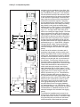
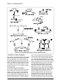
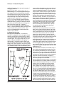
X-Array™ Loudspeaker Systems
angles between enclosures also applies to the
Xrss when determining angles between the top
enclosure and the ATM grid:
Angle = 7.2°- (Holes Showing) x 1.8°for the Xrss
where negative (“-”) angles indicate downward angles and positive (“+”) angles indicate
upward angles.
For example, when the short Xrss straps are used
between the ATM grid and the top enclosure for
0° relative angle between the two (position “0-4”),
there are 4 holes showing as illustrated in
Figure 12b. This means that the formula for the
short Xrss strap must be offset by 4 compared to
the long Xrsl strap; or in this example, 7.2° (4 x 1.8°) = 0°. If the fittings on the Xrss short
straps are inserted into track cutout #1 on the grid
and track cutout #0 on the top enclosure (position
“1-0”), as shown in Figure 12c, one hole is showing and the top enclosure is angled 7.2° (1 x 1.8°) = +5.4° upward relative to the grid.
Multiple Enclosure Angles: The relative vertical
angle between the grid and the top enclosure or
between adjacent enclosures is determined by
the attachment position of the Xrss and Xrsl rigging straps in the rigging track in the grid and enclosures. Note that the straps set the relative
angles between grid and enclosures, and that
those relative angles are cumulative when determining the absolute angle of the enclosures lower
in the array. This is best illustrated by the example shown in Figure 13.
An Xrss rigging strap is attached at position 1-5
between the ATM grid and the top enclosure,
resulting in a relative angle between the grid and
enclosure of -3.6°. (See the sections immediately
above for how to calculate the relative angles
based on the rigging strap attachment locations.)
Since the grid is level at 0°, the absolute angle of
top enclosure is -3.6° (pointing down). Moving
down the array, an Xrsl rigging strap is attached
in position 1-2 between the first and second enclosures, resulting in a relative angle of -5.4° between the two. In other words, the second
enclosure is angled down 5.4° more than the top
enclosure, making the absolute angle of the second enclosure -3.6° -5.4° = -9.0°. Finally, an Xrsl
rigging strap is attached at position 2-2 between
the second and third enclosure, resulting in a
relative angle of -7.2° between the two. In other
words, the third enclosure is angled down 7.2°
more than the second enclosure, making the absolute angle of the third enclosure -3.6° -5.4°-7.2°
= -16.2°. Thus, the absolute vertical angle of any
enclosure in an array, is the sum of all of the relative angles of the enclosures above.
2.3 Adjusting Horizontal Angles
When using the ATM Fly-WareTM MEGS-4000-T
grid, the horizontal shape (the splay angles between array columns) of a loudspeaker array is
POSITION 1 - 5 (-3.6°)
Xrss
-3.6°
POSITION 1 - 2 (-5.4°)
Xrsl
-9.0°
POSITION 2 - 2 (-7.2°)
Xrsl
-16.2°
FIGURE 13 - THE RELATIVE ENCLOSURE ANGLES
ADD IN A COLUMN
page 12