1
t (,ectrticp o,weryed
HXTRAEEtr.'{EHF
ALMOST-RE /DY-TO-FLV
A s s e m b l yM a n u a l
Congratulationson your purchasingof this excellentalmost-ready-to-flyR/C
model! This ARF adopts the latest 3D design featuresand emphasizeshigh
performance,light weight and fun. The plane is designedby professional
engineersand built by skilled craftsmen. Many of the parts are abeadypreinstalledfor you!
Cautions: This R/C modelis not a toy!
1.
The RC aircraft is not a toy! If misused,it can causeseriousbodily harm and damageto property.
Fly it only in openarea,following all instructionsincludingyour RadioandEngine.
2.
As this product is designedfor high performance,incorrectinstallationwould affect the flying
performance. Pleaseask for instructionsfrom an experiencedmodeler if you couldn't assembleit by
yourself.
Becausethe packagecontainssomesmall parts,pleasekeep the children away while assembling
3.
them.
4.
For safetyreasons,pleaseconsidereverypossibleaccidentwhen operatingthis model airplaneand
follow your club/countryrules.
5.
T h i s m o d e li s d e s i g n e df o r 4 5 0 - 7 0 0 w a t ct l a s sP o w e rS y s t e mp, l e a s eu s et h i s r e c o m m e n d eedl e c t r i c
motor.
Always keepthis manual,which will be helpful during assembly.
6.
Features:
o
Light weight construction
o
o
High structuralstrength
Superquality
O
o
PVC canopyassembly
Lateststructure
Two piecesof wings
Easyinstallation
O
Excellentaerobaticsand 3D performance
o
o
o
o
Complete
accessories
High performancehardwareincluding:Carbonfibre wing tube
Carbonfibre controlhorn
EXTRA 260-40E.PSpecifications
W i n g S p a n :5 4 i n ( 13 7 0 r n m )
L e n g t h :5 1 . 8i n ( l 3 1 5 m m )
W i n g A r e a :4 5 . 5 s qd m
W e i g h t : 6 5 - 7 0o z ( 2 0 0 0 9 )
Recommended
O
o
O
O
JRsystems
JR 9X or JR 9XII
JRPCM lOX
Futabasystems
O
O
O
F u t a b a9 C H P S
I2ZAP
14MZA
A d d i t i o n a l R e q u i r e dE q u i p m e n tR a d i o E q u i p m e n t
O
O
4-channelradio system(minimum)
4 mini/standardservos
Recommended
Power System:
Brushless
DUALSKY XM4250CA-7
S p e e dC o n t r .
DUALSKY XC6048BA
B a t t e r y - - - - - - - - - - - - - - - - D U A L S KXYP O W E RX P 330 0 4 c T 2 5 C
P r o p e l l e r - - - - - - - - - - - - - - A PI C
5 x 6 E3 D
O t h e r I t e m s N e e d e d( n o t i n c l u d e di n t h e k i t )
O
O
o
o
O
6 " s e r v oE x t e n s i o nf o r M i n i S e r v o s
2 4 " s e r v oE x t e n s i o n Ix
2" Spinner
L o n g s e r v oA r m ( s i n g l e ) * 3
Long rr"rdder
servoArm(dual)xI
Additional Requiredtoolsand adhesives
Tools
a
a
a
o
o
o
O
o
A d j u s t a b l ew r e n c h( s m a l l )
4-40Tap
C a n o p ys c i s s o r s
D r i l l ( d r i l l p r e s sp r e f e r r e d )
D r i l l b i t : l m m - 6 m ms e t
Drumsander
Cutoff wheel
F l a t b l a d e s c r e w d r i v e rw / s h o r t
handle
o
Hexwrench
o
o
o
o
a
o
o
o
o
o
H o b b yk n i f e
M a s k i n gt a p e
P h i l i p ss c r e w d r i v e( rs m a l l )
R a z o rs a w
Scissors
Square
Syringes
T a ph a n d l c
Toothpicks
V e l c r os t r a p s
o
o
M e d i r - r nCtA G l L r c
T h r c a dl o c k
Adhesives
O
5 - m i n u t ee p o x y
O
30-minutepoxy
O t h e r R e q u i r e dI t e m s
o
o
o
O
O
E p o x yb r u s h e s
o
o
Felt-tipped
p e no r p e n c i l
M e a s u r i n gd e v i c e( e . g .r L r l e rt ,a p em c a s u r e ) a
o
M i x i n g s t i c k sf o r e p o x y
o
P a p e rt o w e l s
O
P e t r o l e u rjne l l y
R u b b i n ga l c o h o l
Sanding
bar
S a n d p a p e( rc o a r s e )
C o v e r i n gi r o n
D e n t a fl l o s so r s t r i n g
BeforestartingAssembly
B e f o r eb e g i n n i n gt h e a s s e r n b l o
y f t h e s em o d e l s ,t h o r o u g h l yi n s p e c t h e f u s e l a g ew
, i n g p a n e l s ,r u d d e r ,
a n ds t a b i l i z e rI.f y o u f i n d a n yp a r td a m a g e do r r n i s s i n gp, l e a s ec o n t a c t h e l o c a ld e a l e r .
I f y o u f i n d a n yw r i n k l e si n t h e c o v e r i n gu, s ea h e a tg u n o r c o v e r i n gi r o n t o s m o o t ht h e m .
L Wing Assembly
t
o
o
,\
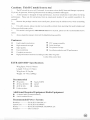
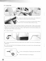
G l u et h eh i n g e si n t o t h e a i l e r o n m
. a k es u r ea l l h i n g e sa r ec e n t e r e d
b e t w e e nt h e w i n g a n da i l e r o n .
Insertthe hingesinto the hinge slotsin the wing. Move the controlsurfaceup and down to ensure
i t s flexibility,and adjustthe gap betweenthe wings andthe ailerons.Securethe hingeswith CA glue.
@
o
Installthe servoarm onto the servo.
o
If usingmini servos,pleaseuseSTD-MINI
ServoAdapters.
O
Use a hobby knife to removethe coveringover the servo
opening.
O
Use the string to pull the servo lead through the wing. Then
installthe servo.
O
Adiust the centersectionof the servo.
: *- - .::::::;:::;t::;
-.;':
-.: -: *..:r- - *:::----:j
II
a
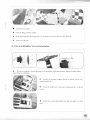
Remove the coveringover the mounting hole for the control
h o r nw i t h h o b b yk n i f e .
o
+
O
Insertthe controlhorn into slot and fix it with slue.
O
Measurethe linkagelengthandcut it to an appropriatelength.
Installthe controlrod and linkagestopper,tightenthe screwsof servo.
R e p e a t t h e a b o v e s t e p sf o r t h e r e m a i n i n g a i l e r o n .
I]: M3ir|119:lSG_:lII"starration
o
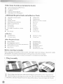
Insertthe wheelaxle throughthe centerhole of the wheel.
O
Installthe wheelcollar and locknut,ensurethat the wheelrolls freely.
@
O Insert the axle through the hole in the landing gear,andattachthe axle for the main landing gear
firmly with the samelocknut.
O
Install the main landing gear on the bottom of the fuselage.
Placea threadlock on the threadsof the landing gear mounting
bolts, using "thread lock" on the screws to keep them from
vibrating during fl ight.
O
Insertthem throughthe landinggearand rotatethem into the
blind nuts firmly,which have been installedin the landing gear
olate.
N o t e : U s et h r e a d l o c k w h e n a t t a c h i n ga l l n u t s t o b o l t s d u r i n g a s s e m b l y .
o
Put the wheelpant onto landinggear,parallelthe wheelpantto fuselage.
o
Measurethe locationof screwsanddrill two holeswhich diametershouldbe 1mm.
o
Usetwo screwsto fix the wheeloant.
a
Rotatethe two nutsand adjustthe wheelto seeif it is centeredin the wheelpantwithout rubbing.
III.Tail surfacesInstallation
o
Horizontal tail
o
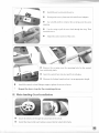
Measureand mark the horizontalstabilizerwhere it passesthroughthe fuselage. Use a Hobby
knife to trim off the coveringfrom the stabilizercentersectionasper your mark.
NOTE: Be ver y car eful not to cut or scor eth e bal s a
under neathas this might causestr uctur al fa i l ur e i n
flight.
O Put the elevator connectorinto the slot before installine
h o r i z o n t asl t a b i l i z e r .
O
Insertthe horizontalstabilizerinto the fuselageslot. Adjust it
to be symmetric and equidistant from the left to right,
perpendicular
to the fuselageandparallelto the wings.
o
A p p l y e p o x yg l u et o s e c u r et h e s t a b i l i z e r .
O
Slide the hinges into the factory pre-cut hinge slots in the
elevatorand thenapply thin CA to securestabilizer.
a Insert the elevatorsconnectorfor the elevatorhalves.Each
hinge must be insertedto their respectivehinge slot in the stabilizer.Secure
the elevatorconnectorprior to gluing the hinges.
O
Adjust the gap betweenthe two elevatorsandthe horizontal
stabilizer.Move the elevatorsuo and down to obtain sufficient
deflection.
o
Once you are satisfied with the deflection, securethe
controlsurfacewith CA slue.
o Vertical Tail
a
"*,1r&
%
\.\
'Sa
,/r)
b
I
I
O
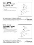
Insert the vertical fin into the mount on the fuselageand
mark wherethe verticalfin mateswith the fuselase.
O
C u t a n d r e l n o v et h e c o v e r i n go n t h e g l u i n gs u r f a c em a k i n g
s u r en o t t o s c o r eo r c u t t h eb a l s au n d e r n e a tthh e c o v e r i n g .
o
I n s e r tt h e v e r t i c a lf i n i n t o t h e f u s e l a g ea n d a d j u s ti t s h e i g h ta n d a n g l e . M a k e s u r et h e t r a i l i n g
e d g eo f t h e v e r t i c a lf i n i s i n l i n e w i t h t h e a f t e n do f t h e f u s c l a g eE
. n s u r ct h e v e r t i c a l f i na n dh o r i z o n t a l
stabrlizea
r r e a t 9 0 d e g r e e sV
. e r i f y t h i s b y u s i n ga s q L l a r e
p l a c e do n t h e h o r i z o n t a ls t a b i l i z e ra n d
a l i g n i n gt h e s q u a r ew i t h t h e v e r t i c a ls t a b i l i z e r .
S e c u r ei t w i t h g l u e .
Erl
o\
O
M e a s u r et h e l o c a t i o no f h o l e t h a ty o u n e e dt o d n l l o n t h e r u d d e r T
. h e l o c a t i o ni s f o r b e n d i n gt a i l
landinggear.
O
Drill a hole that fit for the tail landinggear.And make a slot which both the width and the depth
are2mm on the rudder.
O
Let the wire throughthe tail langinggearmount and wheel
co11ar.
o
Measureandbendthe w i r e t o 9 0 d e g r e e s .
I
O
Installthe tail wheel .
a
Glue the hingeinto the rudder.
O
Insertthe hingeinto the hingeslots.Atthe sametime, Insertthe wire into the hole.
O
Secureit with glue.
o E l e v a t o r & R u d d e rS e r v o sI n s t a l l a t i o n
o
If you usemini serv,install the long servoarm(dual,high performance,madeof carbonfiber)
onto the servoofrudder.
O
Install the linkage stopperfirmly, we adviseyou to use
somethreadlock.
O
Placethe rudderservointo servoplate,andfix it with the
screws.
O
Insert the control horn(dual)into the slot and fix it with
slue.
@
}1
,v:r{51r
t.:,,,.rr..,r
,{e
, . t : r r a t . , , ,, 'i ,' :
,r:..4,,
-trl
'
r
O
Cut the cable into two equal pieces,which need to be
passedthroughthe crimp and control horn, then back through
the crimp twice and completethejob by a crimpingtool.
O
Passthe cable into the fuselagethroughthe slot.Youcan
usea wire to leadthe cable.
O
Passthe cablethroughthe linkagestopper.
o
Tishtenthe bolt to fix it.
o
Install the long servo arm(single,highperformance,made
ofcarbon fiber) onto the servoofrudder.
o
Installthe linkagestopperfirmly with the threadlock.
O
Connectelevatorservowith a 24" servoextension,either
tie the servo leads together,using a commerciallyavailable
connector,or useunwaxeddentalfloss to securethe extensions
to preventthem from cominglooseduringflight.
O
Placethe servointo the servohatch.And Install the servo
firmly with the screws.
O
Install a controlhorn.
O
Measurethe linkagerod lengthand cut it to an appropriate
length.
O
Install the linkage stopper,and fix them firmly.
IV. Motor Installation
t-'',1
)L;I
-r-..
b o x i n t o t h e s l o t sof the firewall,
i n t op l a c e .
O
and
o
o
he left andright side seperately.
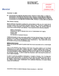
o The firewall can fit two type
o f p o p u l a rl n o to r s t h a t i s e a s y
,
I toget.
'
O U s e r c a n m ount the motor
d i r e c t l yo n t o f i r e w a l l ,i f m o t o r
; i s a b i t s h o r t ,u s e b o l t c o m e
I with the box to adjust the
length.
l"i
I
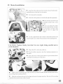
O
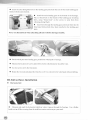
U s et h c s u p p l i e db o l t sa n dw a s h e r st o m o u n tt h e m o t o rt o t h e
m o u n t i r . rpgl a t e .p u t a d r o po f t h r e a dl o c k o n t h e m o u n t i n gb o l t s .
CAUTION: Tighten firmly, but don't be over tight, being careful not to
c r u s ht h e p l a t e .
\,-'b
O
M o u n tt h eE S Cw i t h n y l o n c a b l et i e s .
O P l u g t h c b u l l e tc o n n e c t o r s i n t o t h e i r m a t r n g c o n n e c t o r so n
t h em o t o r .
o
Securetl-rewires with a nylon cabletie to preventthetnI'rom
t o u c h i n gt h er o t a t i n gc a s eo f t h em o t o r .
\
II
^L"L*!
Apply a pieceof maskingtapeon the line whereyou haveto makethe holesfor the screwsto fix
t h e c o w l i n g ,t h e nr r a r k t h ep o s i t i o n .
O
. h e r e a ro f t h e c o w l i n g
S l i d et h e c o w l i n gi n p l a c e o nt h e f u s e l a g ea n d e n s u r ei t s p r o p e rp o s i t i o n T
shouldbe flush with the rearof the firewall.
o
O
Make surethe prop shaft is centeredin the cowling opening.
o
U s e a s m a l l d r i l l b i t t o drill four small holes and use the self-tappingscrewsto securethe
cowling.
O
Readthe manualfor the motor.Choosesuitablepropeller
on the motor according to the suggestionsfrorn the motor
manufacturer.
o
r n d2 i n c hs p i n n e r
I n s t a l lt h ep r o p e l l e a
N o t e : D o n o t u s e t h e d a m a g e do r c r a c k e d p r o p e l l e r
a n d s p i n n e r ,w h i c h c a n b e b r o k e n a t h i g h s p e e da n d
c a n c a u s es e r i o u sd a m a g et o b o d y a n d p r o p e r t y !
V
Wing & Hatch Assembly
N o t e : W h e n o p e n i n gt h e c a n o p yh a t c h , p l e a s em a k e s u r e n o t t o s q u e e z ei t , t h e r e a r e
f o u r s t r o n gm a g n e t s .
O
B i n d t h eb a t t e r yi n p l a c ew i t h V e l c r o .
O
C o n n e c st e r v o sa n dE S Ct o r e c e i v e , b udt o n o t c o n n e ctth e
b a t t e r yt o E S C .
o
Thenbind the receiverwith Velcro.
O Removethe coveringfrom
the bottom of the fuselageas
it is shown in order to allow
cool air to escapefrom the
fuselage.
O
Use the wing tube to attach
the wing halvesto the fuselage.
O
\
\
I n s t a l lt h e n y l o n r e t a i n i n g
screws from the inside of the
fuselage.
N o t e : T i g h t e n t h e s c r e w so n l y b y h a n d a n d n o t t o b e o v e r t i g h t .
O
C h e c kt h e C G , i f t h e C G a t t h e r i g h t l o c a t i o n ,n o w y o u c a n
c o n n e c t h ep o w e ra n dp l a c et h eh a t c h .
I
T
_t-
O
E
T h e m a g n e t st h e r e c a n ' t l o c k t h e h a t c h i n p l a c e c o m p l e t e l y ,
y o u n e e d t o s e c u r ei t b y u s i n g t h e s c r e w s .
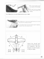
Adjust the arrcraft and
m a k es u r eb o t h o f t h e s i d e s
are symmetric, like the
d i a g r a m. S o t h a t t h e p l a n e
is readyfor flight.
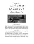
Measurethe CG from the leadingedge
of wing root rib, Adjust the battery
packlocation.For CG properposition
s h o u l d b e a t 2 5 - 3 0 % M A C .T h r s
recommendation
balancepoint is for
your first flights.The CG can be
moved ar ound later to fit y our
personaltaste.
MAC:
C GL o c a t i o n :
25%
96mm
2-3l4inch
27%
l03mm
3i n c h
30%
I l5mm
3- 3 1 8 i n c h
1.
C h e c keve rya n g l ea n da d j u stthemto cor r ectposition.
2.
C h e c kal l p a rtsa n dma kesu rethe installationis fir m andr eliable.
3.
Ad d s o mew e i g h ti n e i th e ro f w ingtip to balancethe left andr ight wings.
P o w e ro n t o t r i m y o u r p l a n e .
1.
R a n g ech e ckth e ra d i o(te stw h etherthe m otoris r unningor not ) .
2.
En s u r eth a t th e se rvo sa n d co ntr ol sur facesmove smoothlyand ar e in the cor r ec t
d ir e c t i o n .
3.
Ad j u s t th e se rvoth ro w . T h e char tbelow is the r ecomm ended
thr owsfor the fi r s t
flight. You canadjustthe servoarmsand controlhorn lengthlater to fit your flying style.
Control Throws :
C o m m o n fl yi n g
3D flying
Surface
Throws
Aileron
Elevator
20 degrees
20degrees
Rudder
30degrees
30%
Aileron
40 degrees
45%
E l e va t o r
40 degrees
45%
Rudder
45 degrees
4s%
E^p
2s%
25%
rail run the motor to checkits stability at high speedand low speedto
ensurethereareno problemswith vibrationon the model.Run the motor
at high speedabout30min,checkthe ESC/Batteries
and motor and makesure
the temperature
is below the prescriptionof manufacturer.Once
everythingis
risht
fun!
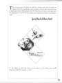
$oodluck&Hsve
"';;-o&fr7|+Z EEE sryEre
..-o*''^^^-""- **
*
SS
**
Do forget to stick the decal on the plane,it will make your model
beautiful and focus people's e y e s!