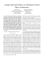
1
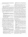
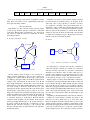
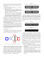
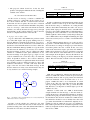
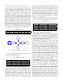
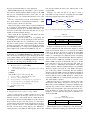
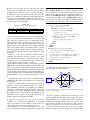
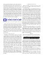
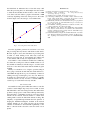
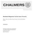
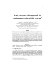
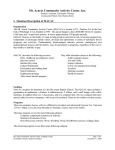
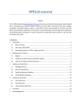
Coping with Link Failures in Centralized Control
Plane Architectures
Maulik Desai
[email protected]
Department of Electrical Engineering
Columbia University
New York, NY 10027
Abstract—Recently proposed SoftRouter and 4D network
architectures recommend having the least amount of intelligence
in the switches. They advocate transferring control plane
functionalities to general-purpose servers that could govern
these switches remotely. A link failure in such architectures
could result into switches losing contact with the controller or
even generating routing loops. These scenarios could generate
a large amount of unnecessary traffic in the network. We
study the implications of a failed link in such architectures.
We develop an algorithm that would inform only the relevant
switches to refrain from sending messages in the direction of the
failed link, and yet have the minimum amount of intelligence
on the switches. We implement our algorithm on a network
formed by OpenFlow switches and evaluate its performance.
Our experiments verify that the performance of our algorithm is
dependent on the total number of flow-table entries in a switch.
We also verify that by implementing our algorithm all the
necessary switches are informed of the failed link significantly
sooner than the controller identifies the failed link and sends
out an update.
Index Terms—Link failures, Centralized control plane
I. I NTRODUCTION
Some of the recent research efforts emphasize on maintaining a centralized control plane in a network, instead of
having routers make their own control decisions. In such
architectures routers could be replaced with the switches that
would have the least amount of intelligence, and all the
control plane functions of these switches could be handled
by a centralized authority such as a general-purpose server.
While a centralized control plane could help establish a firm
grip over the network’s behavior, this new architecture also
introduces a new set of problems. One such problem is link
failures. SoftRouter [6], [8] and 4D [4] are two of the proposed
centralized control plane architectures, in which a switch has
to rely on a remotely connected controller to make all of its
control decisions. In traditional networks, every time a link
fails a router identifies the failure and establishes an alternate
route. However, in SoftRouter/4D architectures even though
a switch could identify the failed link, it has neither the
intelligence nor the global knowledge to establish a new route.
It must depend on the updates from the controller to establish
an alternate route. Until a controller identifies a failed link and
updates flow table entries in all the relevant switches, packets
that are supposed to travel on the failed link will be dropped.
c
978-1-4244-5489-1/10/$26.00 2010
IEEE
Thyagarajan Nandagopal
[email protected]
Bell Laboratories
Alcatel-Lucent
Murray Hill, NJ 07974
Therefore, until a controller sends an update, it is important
to prevent the traffic going towards the failed link to preserve
the processing resources of the network.
In many cases a group of switches could completely get
disconnected from their controller due to a failed link, and
start sending out messages to reach their controller. In such
cases it is important to instruct these switches to stop their
attempts to find a controller, since all their efforts are going
in vain.
In large networks different sets of switches may be controlled by different controllers. If a link fails in such scenarios
and the controllers make conflicting decisions in establishing
new routes, it could lead to forming routing loops in the
network. Routing loops induce a large amount of unnecessary
traffic in the network, hence it is important to take precautions
to prevent any loops in the network that could be formed by
a failed link.
To avoid the problems created by a failed link it is important
to come up with a way to inform all the relevant switches of
this event, and ask them to refrain from sending messages
in that direction. While flooding the news of a failed link
could easily accomplish this objective, it disregards the idea
of keeping the unnecessary network traffic to a minimum.
Therefore, we devise a way such that only the necessary
switches will be informed of the link failure. Furthermore,
we accomplish this without violating the basic premises of
maintaining the minimum amount of intelligence available on
the switches. We implement our scheme in a network formed
by OpenFlow [7] switches and verify that the news of the
failed link reaches network switches a lot sooner than the
controller can identify the failure and send out an update.
OpenFlow switches are open source switches that could be
controlled by a remote controller. Therefore, it is possible
to create a SoftRouter/4D network architecture using these
switches. They provide a great deal of flexibility in defining
network flows, and it is quite easy to observe these flows.
Therefore they are very useful in observing the performance
of our scheme.
The rest of the paper is organized as follows. In section II we
provide an overview of SoftRouter and 4D architectures. We
also give a small overview of OpenFlow switches in the same
section. Section III elaborates on the problems introduced by
link failures. In section IV we give a solution to overcome the
problems introduced by link failures. Section V analyzes our
algorithm and presents the results of our experiments. Finally,
section VI presents the conclusion.
II. R ELATED W ORK
SoftRouter and 4D architectures are two of the proposed
centralized control plane architectures.
SoftRouter architecture was proposed by Bell Labs. While
in existing networks a router’s control functions and packet
forwarding functions are tightly interwined, SoftRouter architecture advocates separating both of them. Since the control
functions run on every router, maintaining a large network
is extremely complex and expensive. Authors of SoftRouters
hope to gain some simplicity in a network by separating the
control and packet forwarding functions of a router.
Elements of a SoftRouter network could be classified as
follows.
•
•
•
Forwarding Element (FE): FEs are basically switches
that perform packet forwarding and switching functions.
They have minimum amount of control functions running
on them.
Control Element (CE): CEs are general purpose servers,
they are connected to multiple FEs and run the control
plane functions on behalf of them.
Network Element (NE): NE is a logical grouping of
some CEs and a few FEs.
It is suggested that by separating control and packet forwarding functions SoftRouter architecture could also increase
reliability in a network. An IP router could have hundreds
of thousands of lines of code. With such a high amount of
software running on every router in the network, probability
of the control plane functions making a mistake is very high. If
control functions could be governed by a centralized authority
(CE), and the packet forwarding functions could be given to
the switches with little software on them (FE) , probability of
a control plane error could be greatly reduced.
Besides simplicity and increased reliability, authors of SoftRouter also make a case for scalability, control plane security,
reduced cost, and ease of adding new functionality.
4D architecture is another proposed scheme whose design
and benefits are similar to SoftRouter. Authors of 4D architecture suggest splitting a network into four logical planes.
•
•
•
Decision Plane: Decision plane makes all the decisions
regarding network control. It is made up of multiple
servers called decision elements.
Dissemination Plane: Dissemination plane is responsible
for efficient communication between the decision elements and network switches. Dissemination plane maintains separate paths for control information and regular
data packets. It is more of a logical entity and may not
be comprised of any physical element.
Discovery Plane: Discovery plane is responsible for
identifying physical components of a network such as
switches. This plane is also a logical plane.
•
Data Plane: Data plane is controlled by decision plane,
and it is primarily responsible for handling individual
packets.
Authors of 4D architecture indicate that this scheme could
offer further robustness, increased security, more heterogeneity
and a separate networking logic from distributed systems.
Both SoftRouter and 4D architecture share one thing in
common, that is they maintain a separate control plane
from the data plane. Moreover, packet forwarding elements
(switches) are controlled remotely by control elements that
could be multiple hops away from the switches.
While we develop a solution that will prevent unnecessary
traffic from floating around in a network during an event
of a link failure, it is important to test this solution too.
However, most of the commercial switches are closed boxes,
and hence they fail to give a good insight into network
management. In recent years many academic researches have
turn their attention to developing open platforms that could
help researcher experiment with various networking protocols.
Geni [1], XORP [5] and OpenFlow [7] are some of such
efforts. To test our solution to overcome link failure problems,
we use a network formed by OpenFlow switches. OpenFlow
switches could be controlled by a remotely located controller,
hence it is suitable for creating networks with a centralized
control plane. OpenFlow switches allow maintaining multiple
data paths in the same network such as production flows and
research oriented flows. Furthermore, these switches easily
allow network administrators to add, remove and monitor
flows in the network.
Each OpenFlow switch maintains a flow table. A flow table
entry has three main parts [2].
•
•
•
Header Fields: Table I shows a sample flow table header.
In OpenFlow switches a flow could be defined according
to the fields in this header. For example, a flow could
be defined according to the ingress port, or it could be
defined according to the destination’s IP address. A flow
could also be defined as the combination of multiple
header fields. The header fields that are defined as “ANY”
or left blank in the flow table are considered to be wildcard entries.
Counters: Counters maintain statistics for the switch.
They keep count on how many packets are received,
transmitted, dropped etc.
Actions: If the header of a received packet matches with
the header fields specified in a flow table entry, action
defined in this field is applied to that packet. An action
could be transmit the packet to a certain interface, drop
or flood the packet etc.
Once an OpenFlow switch receives a packet, this packet is
matched against the flow table entries. If the packet matches
with a flow table entry, action specified in that entry is applied
to the packet. However, if a packet does not match any of
the entries, it is transmitted to the controller through a secure
channel. Secure channel is simply an interface that connects
the OpenFlow switch to its controller.
TABLE I
F LOW TABLE ENTRY HEADER
Ingress
Port
VLAN
ID
Ethernet
Source
Ethernet
Destination
Ethernet
Type
IP
Source
Ease of use and open source nature of OpenFlow switches
make them very useful tools for experimenting with newly
developed networking schemes.
IP
Destination
IP
Type
TCP/UDP
Source Port
TCP/UDP
Destination Port
Link failures are quite common in large networks. Based
on the topology and flow structure of a network, a failed link
could have different kind of implications on a network. In
this section we study the effects of a failed link on various
networking scenarios.
Naturally, it is unwise to have packets floating around in
the network that are eventually going to be dropped. At the
same time, since a large amount of controller’s resources
are occupied in executing control plane functionality, it is
imprudent to impose additional computational burden on the
controller by asking it to manage the undelivered packets.
The best option in this situation is to inform all the relevant
switches in the network about the failed link, and ask them
to refrain from sending messages to B that travel towards A,
until the controller sends them an update.
A. A simple link failure scenario
B. Island
III. L INK FAILURE
I
C
10.0.4.1
10.1.0.0/16
A
H
Controller
10.0.1.1
B
C
G
F
Fig. 1.
B
10.0.3.1
D
10.0.5.1
E
D
A
10.0.2.1
Fig. 2.
Formation of an island due to a failed link
Controller
A simple link failure scenario
All the switches shown in figure 1 are controlled by a
single controller. Furthermore, flows in these switches are
configured in a manner that all the messages going towards
10.1.0.0/16 go through switches A and B. In regular network
settings, if the link between A and B fails, node B will
have enough intelligence to find another route for 10.1.0.0/16
traffic. However, in SoftRouter/4D architectures switches are
not clever enough to divert the traffic and wait for some
instructions from the controller. Since the controller may have
the knowledge of the global topology it could do one of two
things. The controller can recalculate an alternative path going
towards 10.1.0.0/16 and it can either update the flow tables of
all the switches in the network or it can simply instruct B
to send these messages to A through C. However until the
controller sends an update, all the switches in the network
will keep sending their messages to B, and B will have to
drop these packets. If the network is configured in a proper
manner B can send these messages to the controller, and
have the controller figure out what should be done with these
undelivered packets.
It is important for a switch in the network to maintain its
connection with the controller. If a switch loses connection
with the controller, often times it is possible to establish an
alternative route. However, there are times when part of a
network could completely get segregated from the rest of the
network, and an island is formed. The switches that are part
of this island do not have a way to reach their controller.
Figure 2 depicts a scenario when a link failure could lead to
the formation of an island. Switches B,C and D are connected
to the controller through A. When the link between A and B
fails, nodes B, C, D do not have a way to reach the controller.
These three segregated switches form an island. As mentioned
earlier, switches in SoftRouter/4D architectures do not possess
much control plane functionality, hence losing contact with
the controller could adversely affect the functionality of the
network.
Depending on the implementation of the network, whenever
a switch loses contact with its controller, the switch or the
controller (or both of them) may try to reach each other.
However, whenever an island is formed, there is no way for the
switches and the controller to establish a contact. Hence switch
B will end up dropping all the packets from the messages that
come from C and D and try to reach the controller. Thus,
all the attempts by B, C, D to reach the controller result into
unwanted and unnecessary traffic. Similarly switch A will also
drop all the packets that come from the controller and try to
reach B, C, D.
For example, OpenFlow implementation of a switch offers
two kinds of functionalities.
• fail−closed: In fail−closed mode, whenever the connection between the switch and the controller fails, the
switch does not take any actions, it simply waits for the
controller to establish a new connection.
• fail−open: In fail−open mode, the switch becomes
proactive and tries to reach the controller periodically
once it loses the connection with the switch. By default,
the period between two such attempts increases exponentially, with the maximum wait period of 15 seconds.
Switches B, C and D do not necessarily have the global
knowledge of the network topology, hence they may not have
the intelligence to avoid sending message towards the controller whenever an island is formed. However, it is possible
for B to check whether all of its links are up and working. If
B could inform its neighbors of the failed link, it is possible
to avoid this unnecessary traffic.
On the other hand, even though the controller could have the
knowledge of the global topology, it will keep trying to reach
the switches that belong to the island. It does not immediately
know that the link between with A and B is broken. If A could
inform the controller of the broken link, its attempt to reach
the island could be prevented.
C. Routing Loop
In many cases link failure could lead to forming routing
loops. Routing loops also adversely affect a system’s performance by increasing network traffic significantly.
2
B
10.0.3.1
3
1
1
2
Controller:I
10.0.1.1
1
1
A
10.0.2.1
Controller:II
10.0.5.1
3
2
1
2
3
C
10.0.4.1
Fig. 3.
An example of routing loop caused by a failed link
Figure 3 demonstrates a scenario where a link failure could
result into routing loops. In this figure, switch A is controlled
by Cotroller: I, and switches B,C are controlled by Controller:
II. IP addresses of the switches and their interface names are
labeled in the diagram. Let us assume that the flows in this
network are defined according to destination IP addresses.
Flow tables of switches A and B are shown in tables II and
III. According to these flow tables, messages coming from A
and going towards C have to go through switch B.
TABLE II
O RIGINAL F LOW TABLE FOR SWITCH : A (F IGURE 3)
Destination’s IP Address
10.0.4.0/24
Action
Forward to interface# 2
TABLE III
O RIGINAL F LOW TABLE FOR SWITCH : B (F IGURE 3)
Destination’s IP Address
10.0.4.0/24
Action
Forward to interface# 1
However, the link between switches B and C fails and the
controllers decide that the messages destined for C should go
through switch A. While Controller: II successfully updates
switch B’s flow table, switch A is not updated due to the
delay in the network. Therefore, switch B’s flow table gets
updated while A’s flow table remains unchanged as shown in
IV and V.
TABLE IV
U NMODIFIED F LOW TABLE OF SWITCH : A (F IGURE 3)
Destination’s IP Address
10.0.4.0/24
Action
Forward to interface# 2
TABLE V
U PDATED F LOW TABLE OF SWITCH : B (F IGURE 3)
Destination’s IP Address
10.0.4.0/24
Action
Forward to interface# 2
In this case, A will send all the messages going towards C
to B, and B will send them back to A, and thus a routing loop
is induced in the network. This situation could be prevented
if B could inform A that the link between B and C has
failed, and it will no longer be able to forward messages
towards C. This process can be completed a lot sooner than
the controllers could identify a failed link and update their
respective switches, and hence the routing loops could be
avoided.
Considering the scenarios presented in the this section, it
becomes necessary to come up with a scheme that would
reduce the damage caused by a failed link. We outline basic
requirements for such a scheme as follows.
• In case of a link failure, all the switches that could send
flows in the direction of the failed link should be informed
of this event.
• Link failure messages should not propagate in the network indefinitely, and unless required, these messages
should not be flooded in the network.
• The scheme should provide enough information to the
network switches regarding the flows that are affected by
the failed link. At the same time, it should make sure that
the flows that are not affected by this event do not get
modified.
•
The proposed scheme should not violate the basic
premises of keeping the minimum amount of intelligence
available at the switches
IV. S OLUTION TO L INK FAILURES
In this section we develop a solution to minimize the
problems created by a failed link. In the solution we do
not concern ourselves with how a controller learns about the
broken link, and how it updates the flow table of network
switches in order to accommodate the link failure. Our primary
focus is to develop a solution that will inform the network
switches to not send any flows that are supposed to go through
the failed link, yet this solution will have to impose the least
amount of computational burden on the network.
A. A proper way to define a flow
A good solution that could minimize the problems created
by a failed link begins with properly defining flows in a
network. Whenever a link fails in the network, our goal is to
inform this event to all the switches that could send flows in
the direction of the failed link. However, we have to make sure
that these Link Failure Messages (LFM) do not get flooded in
the entire network. Therefore, it is necessary for a switch to
have the knowledge of where a flow is coming from. While
switches in a centralized control plane architectures do not
have the knowledge of the global topology, origin of a flow
could be identified from a flow table entry. As mentioned
earlier, in OpenFlow switches a flow could be defined by
choosing any combination of eight header fields shown in table
I. For example, if a flow is defined according to source’s and
destination’s IP addresses, a switch could easily derive the
origin of the flow and send a link failure message in that
direction. However, in many cases this information may not
be very useful. Let us consider following example.
C
10.0.4.1
2
Controller
10.0.1.1
3
A
10.0.2.1
1
B
10.0.3.1
4
D
10.0.5.1
Fig. 4. An example of why source IP addresses do not necessarily indicate
which direction a flow is coming from
In figure 4 all the switches are connected to the same
controller. Let us assume that the flows in this network are
specified according to the source and destination IP addresses,
and switch A’s flow table is described in table VI.
TABLE VI
F LOW TABLE OF SWITCH A (F IGURE 4)
Source IP Address
10.0.5.0/24
10.0.3.0/24
Destination IP Address
10.0.3.0/24
10.0.4.0/24
Action
Forward to interface# 1
Forward to interface# 2
In such a configuration, if the link between switches A and
B breaks, switch A could look up its flow table and identify
that all the flows that go to interface# 1 are coming from IP
addresses 10.0.5.0/24. Unfortunately flow table of A does not
specify which output port should be used to send link failure
messages to the switches with IP addresses 10.0.5.0/24. Hence,
specifying the source’s IP address is not necessarily useful.
Similar argument could be made to justify that specifying the
source’s MAC address may be helpful in identifying the origin
of the flow, but it may not be too useful to forward link failure
messages.
If a flow definition includes ingress port of a flow as well, it
is possible to send link failure messages to the switches from
where the flows are coming in. An ingress port is the interface
from where packets enter into a switch. In fact, once every
switch in the network uses ingress port in the flow definition,
LFM could be delivered to the every switch that could send
flows in the direction of the failed link. Let us consider the
same example shown in figure 4, however, this time flows are
defined according to the ingress port and the destination’s IP
address. The new flow table of switch A is shown in table VII.
TABLE VII
N EW FLOW TABLE OF SWITCH A (F IGURE 4)
Ingress Port
4
1
Destination IP Address
10.0.3.0/24
10.0.4.0/24
Action
Forward to interface# 1
Forward to interface# 2
With such a configuration, whenever the link between the
switches A and B fails, switch A could look up its flow table,
and identify that flows that are going towards the failed link
come from interface# 4. Now all switch A has to do is to
prepare a LFM, and send it out on interface#4. A switch
located on the other end of that link will receive this LFM
and stop sending messages that could go towards the failed
link. Therefore, it is important to include ingress port in the
definition of a flow.
Whenever a switch sends out a LFM, it should include
enough information in that message, so that the switch receiving this message could understand which flows should be
prevented from going out. In the following section we specify
the information that should be included in a LFM and how
this information should be used to identify flows that could
go towards the failed link. To maintain the simplicity in explaining, we split our scheme into two parts. (1) Computations
that would be performed at the switch that experiences a link
failure (2) Computations that would be performed at the switch
that receives a LFM.
B. Computations for the switch experiencing link failure
Algorithm for the switch experiencing the link failure is
relatively simple. Once a switch learns that one of its link
is down, it identifies the network interface associated with
that link, let us call this interface brokenInterface. Now the
switch will look up its flow table and create a LFM for every
input interface which brings in a flow that could be sent to
brokenInterface. Structure of the LFM is show in table VIII.
If txInterface is one of the interfaces where a LMF is sent out,
this particular LFM will contain the definition of all the flows
that come in from txInterface and go out from brokenInterface.
Finally we modify the “Action” field of the flow table entries
whose flow definitions are attached to LFMs. The new action
will indicate that packets from these flows should be dropped.
If the network is configured properly and the connection with
the controller is not interrupted due to the failed link, packets
from these flows could be diverted to the controller also.
TABLE VIII
L INK FAILURE MESSAGE STRUCTURE
Source
Address.
Message
ID
Flow
Definition
Flow
Count
Flow
Def.#1
···
···
Flow
Def.#n
E
10.0.6.1
2
Controller
10.0.1.1
C
10.0.2.1
3
A
10.0.3.1
1
B
10.0.4.1
D
10.0.5.1
4
F
10.0.7.1
Fig. 5.
A figure demonstrating how to generate LFM
Consider a topology shown in 5. Switch A’s flow table for
this topology is shown in table IX.
TABLE IX
F LOW TABLE OF SWITCH A (F IGURE 5)
Ingress Port
2
3
3
4
4
Destination IP Address
10.0.7.0/24
10.0.4.0/24
10.0.5.0/24
10.0.6.0/24
10.0.4.0/24
Forward
Forward
Forward
Forward
Forward
Action
to interface#
to interface#
to interface#
to interface#
to interface#
4
1
1
2
1
In this example when the link connecting A and B fails,
switch A will look up its flow table and identify that it is
receiving flows from interfaces 3 and 4 that will be sent out
on interface# 1. Therefore A will create two LFMs, one for
interface#3 and one for #4. Even though A is receiving a
flow from interface#2, since this flow is not going out on
interface#1, no LFM will be sent out through 2. Since there
are two flows that come through interface#3 and go out from
interface#1, LFM that goes out through 3, will have two flow
definitions attached to it:10.0.4.0/24 and 10.0.5.0/24. There is
just one flow that comes in from interface#4 and goes out
from interface#1, hence LFM that goes out from 4 will have
only one flow definition attached to it:10.0.4.0/24. It should be
noted that even though we are using ingress port to define a
flow, we do not have to attach that information to LFM, since
ingress ports are switch specific.
Finally we modify the “Action” field of the flow table, and
new flow table of switch A would look like as shown in X.
TABLE X
N EW FLOW TABLE FOR SWITCH A (F IGURE 5)
Ingress Port
2
3
3
4
4
Destination IP Address
10.0.7.0/24
10.0.4.0/24
10.0.5.0/24
10.0.6.0/24
10.0.4.0/24
Action
Forward to interface# 4
Drop / Send to controller
Drop / Send to controller
Forward to interface# 2
Drop / Send to controller
Various fields of LFM are described below.
Source Address is the IP address of the switch that initiates
the LFM. If a network supports MAC level routing instead of
IP routing, IP address could be replaced with the MAC address
of the source. Whichever switch receives LFM, uses this field
to identify where this LFM is coming from.
Message ID field helps make sure that the same LFM
does not get forwarded multiple times by the same switch.
If routes in a network are not configured correctly, the same
LFM could come back at the same switch multiple times. If
a switch receives two LFMs with the same message ID in a
short time period, it disregards the second LFM. The switch
that initiate a LFM, chooses a message ID randomly, and this
value does not change as the message gets forwarded to the
downstream switches. Once a switch receives a LFM, it stores
it in its memory. The next time this switch receives a LFM it
compares it with the stored value, and takes an action only if
the message differs from the stored values. This way a switch
does not propagate the same message multiple times. A stored
LFM could be discarded after receiving an update from the
controller or after a predefined time interval expires.
Flow Definition field lists a subset of header fields shown
in table I that make up the definition of a flow. While it is
possible to attach all the eight fields in the LFM to define
a flow, it could increase the length of the message. Also
since not always all the fields are used to define a flow, it
is unnecessary to add all eight header fields of a flow in LFM.
Therefore flow definition field indicates which information is
attached with this message. Each field in table I is given a
numerical representation, and this value is included in the
Flow Definition field of a LFM. For example, for the scenario
presented in figure 5, whenever switch A creates a LFM, its
Flow Definition field will have the numerical representation of
“Destination IP Address” field. This way the switch receiving
the LFM will know that the information attached with this
message represent IP addresses of the destination.
Flow Count indicates the total number of flow specifications that are attached with the LFM. For figure 5 the LFM
that goes out of interface#3 will have a flow count of 2, and
the LFM that goes out of interface#4 will have a flow count
of 1.
The rest of the fields provide the actual definition of the
flows. Total number of such definitions attached to a LFM
would be equal to the Flow Count value.
Therefore in figure 5 when switch C receives a LFM from
A, by looking at “Flow Definition” field it will know that the
flow definitions are made up of Destination IP Address, and
from Flow Count field it will learn that there are two flow
definitions attached with this message.
Since switch B also experiences a link failure, the same
algorithm will also be run at switch B.
Algorithm 1 gives the pseudo code for preparing and
transmitting LFMs, as well as updating flow table entries. To
update the flow table entry in a switch (line 3), the program
may have to make system a call. Executing shell commands
from the program may take longer. To inform all the switches
about the link failure as soon as possible, updating flow table
entries might be put off until all the LFMs are sent out.
Algorithm 1 Algorithm for LFM initiator upon detecting a
broken link on port brkPrt. FlowDict is a dictionary / hash
table whose keys are the ingress ports that bring in the flows
going towards brkPrt, and the values are the lists containing
the definition of these flows. SendMsg(prt, msg) is a function
that sends out a message (msg) through port (prt).
1: for each entry ∈ F lowT able do
2:
if entry.inP ort = brkP rt then
3:
entry.action ← drop
4:
F lowDict[entry.inP ort].append(entry.f lowDef )
5:
end if
6: end for
7: for each key ∈ F lowDict.keys() do
8:
msg.srcAddr ← Self IP/M AC Addr
9:
msg.id ← RandomN umber
10:
msg.f lowDef ← P redef ined f low def inition
11:
msg.f lowCount ← length(F lowDict[key])
12:
msg.f lowList ← F lowDict[key]
13:
SendM sg(key, msg)
14: end for
C. Computations for the switch receiving a LFM
Once a switch receives a LFM, it makes the note of the
interface from where the message came in. Let us call this
interface rxInterface. The switch will also detach the list of
flow definitions attached with this LFM, let us call it flowList.
Next, it will look up its flow table and try to locate ingress
ports that bring in flows that match with the flows in flowList,
and go out from rxInterface. A new LFM will be generated
and sent out from each of these ingress ports. Whenever a
switch generates a new LFM, the “Message ID” field of this
new message remains the same as the “Message ID” of the
original LFM.
Naturally one could ask why do we have to create a
new LFM every hop instead of forwarding the same LFM.
Following example helps answer this question.
10.1.0.0/16
Controller
1
E
2
10.1.0.0/16
10.1.1.0/24
1
C
B
2
A
3
10.1.2.0/24
D
Fig. 6.
An example showing why a new LFM should be created every hop
TABLE XI
F LOW TABLE OF SWITCH C (F IGURE 6)
Ingress Port
1
1
Destination IP Address
10.1.1.0/24
10.1.2.0/24
Action
Forward to interface# 2
Forward to interface# 3
In figure 6 switch B sends all of its 10.1.0.0/16 traffic to
switch A. Whenever the link between the switches A and B
breaks, B will inform switch C to not send any 10.1.0.0/16
traffic in its direction. If switch C forwards the same LFM
to E, switch E will simply stop sending all its 10.1.0.0/16
traffic to C, even though C is completely capable of accepting
and forwarding part of 10.1.0.0/16 traffic. Therefore whenever
switch C receives a LFM from switch B, it will make a note
that this LFM is received on interface#2 (rxInterface). It will
notice that there is just one flow table entry that sends out
flow on rxInterface. Furthermore, flow definition of this entry
matches with the definition attached with the received LFM.
Therefore, switch C will send out a new LFM to the ingress
port of this entry, which is interface#1. The flow definition
attached to this new LFM would be the definition available in
the flow table table entry (10.1.1.0./24) and not the definition
attached with the received LFM. Whenever, switch E will
receive this LFM from C, it will learn that it should not send
10.1.1.0/24 traffic to switch C.
While the next step is to modified the “Action” field of the
affected flow table entries, this part is a bit tricky as well.
Many times a received LFM may contain flow definitions that
represent only a subset of flows defined in a flow table entry.
In such cases it is important to split a flow table entry into two,
before modifying its “Action” field. For the topology shown
in figure 6, let us assume that flow table of switch E is as
shown in table XII.
TABLE XII
F LOW TABLE OF SWITCH E (F IGURE 6)
Ingress Port
1
Destination IP Address
10.1.0.0/16
Action
Forward to interface# 2
When switch E receives a LFM from C, this message will
indicate to refrain from sending 10.1.1.0/24 traffic towards C.
However, E does not have any flow table entry that exactly
matches with 10.1.1.0/24. If it modifies the action field of
10.1.0.0/16 entry, it will not be able to send any messages to
C. Therefore in this case switch E will split this flow table
entry into two. While the original entry will remain intact, the
new entry’s action field will be changed to “Drop packet” or
“Send packet to the Controller”. The new flow table for switch
E will look like as shown in XIII.
TABLE XIII
N EW FLOW TABLE FOR SWITCH E (F IGURE 6)
Ingress Port
1
1
Destination IP Address
10.1.1.0/24
10.1.0.0/16
Action
Drop / Send to Controller
Forward to interface# 2
Now if switch E receives a packet going towards IP address
10.1.2.5, this packet will match with the second flow table
entry and hence it will be sent out on interface#2. On the
other hand if E receives a packet going towards 10.1.1.5 on
interface#1, this packet will match with both the flow table
entries, however, most of the switches are configured such that
when a flow packet matches with multiple entries, only the
entry with the highest priority will be considered. Therefore,
in this particular case the packets going towards 10.1.1.5 will
be dropped.
While one could come up with cases where instead of
splitting a flow table entry, we have to merge or even delete
some of the entries. However, we refrain from doing so, since a
switch does not possess the global knowledge of the topology.
This task is left for the controller to complete.
This LFM forwarding procedure could continue until the
LFM reaches an end host. Since LFM is forwarded only to the
ingress ports which could potentially bring in packets going
towards the failed link, a LFM will only reach the switches that
could send a flow in the direction of the failed link. Therefore
only the relevant switches are informed about the link failure,
and the LFM does not go to the switches that have no use of
it.
Algorithm 2 gives the pseudo code for a switch that receives
a LFM and verifies that its message ID is not one of the stored
message IDs.
Finally, we should mention that although we utilize port
numbers to receive and forward messages, if a system is
using DynaBind or ForCES [8] algorithms in a SoftRouter
architecture, switches may have the knowledge of their next
hop neighbors. If a system administrator prefers dealing with
IP addresses instead of port numbers, our algorithm is still
applicable in those scenarios by replacing forwarding port
numbers with next hop neighbor IP address.
D. Importance of specifying ingress port in the flow definition
While so far we have been emphasizing on specifying
ingress port with every flow definition, in this section we
explain how much benefit we can achieve by doing so.
If a switch has a lot of interfaces attached to it, it is not
necessary that all these interfaces bring in the flows that could
Algorithm 2 Algorithm for a downstream switch receiving
lfm on brkPrt. FlowDict is a dictionary / hash table whose
keys are the ingress ports that bring in the flows going towards
brkPrt, and the values are the lists containing the definition of
these flows. SendMsg(prt, msg) is a function that sends out a
message (msg) through port (prt). splitEntry(flow) creates a
new flow table entry whose flow definition is flow, and action
is drop packet. The original flow table entry remains intact.
1: for each entry ∈ F lowT able do
2:
if entry.inP ort = brkP rt then
3:
prt ← entry.inP ort
4:
for each f low ∈ lf m.f lowList do
5:
if f low ⊇ entry.f lowDef then
6:
entry.action ← drop
7:
F lowDict[prt].append(entry.f lowDef )
8:
else if f low ⊂ entry.f lowDef then
9:
splitEntry(f low)
10:
F lowDict[prt].append(f low)
11:
end if
12:
end for
13:
end if
14: end for
15: for each key ∈ F lowDict.keys() do
16:
msg.srcAddr ← Self IP/M AC Addr
17:
msg.id ← lf m.id
18:
msg.f lowDef ← P redef ined f low def inition
19:
msg.f lowCount ← length(F lowDict[key])
20:
msg.f lowList ← F lowDict[key]
21:
SendM sg(key, msg)
22: end for
go towards the failed link. Therefore, it is not necessary to
send out LFMs on all these interfaces.
B
Controller
D
A
F
C
G
E
Fig. 7. Specifying ingress port will be the most helpful in the topology that
is similar to a perfect graph
In figure 7 switches A through F are connected to each
other in a manner such that their topology will form a perfect
graph. Furthermore, let’s assume that flow tables of switches A
through E are configured such that switch G is only two hops
away from these switches. In other words if switch A through
E have a flow that goes to G, this flow will directly go to
F, and from F it will be delivered to G. Let us also assume
that these switches do not have an ingress port specified with
their flow table entries. Therefore, these switches will have to
flood LFMs in the network in order to spread the news of a
broken link. If the link between the switches F and G breaks,
F will generate a LFM and send it out on rest of its five
interfaces. Switches A through E will receive these messages,
and forward them to rest of their four interfaces (all interfaces
except for the one connected to the switch F). For example
when switch A receives a LFM from F, it will forward its own
LFM to the switches B,C,D and E. These switches will learn
that the message coming from A has the same “Message ID”
as the message that came from F. Therefore these switches
will disregard the LFM that came from A. Thus, if we do not
specify an ingress port, instead of sending 5 messages from
F, we end up sending 25 messages to spread the news of the
failed link (5 from F, and 4 from A through E).
Controller
A
B
C
D
E
F
G
Fig. 8. Specifying ingress port could be the least helpful in a chain topology
On the other hand specifying the ingress port could be the
least helpful in a chain topology as shown in figure 8. In such a
case if switch A has a flow for the switch G, it will go through
switches B to F, before it reaches G. Therefore, whenever the
link connecting F and G break, an LFM will have to go through
all the switches to reach A, which is similar to flooding.
However, in the most of the cases a network could be much
more complex than a simple chain topology, hence specifying
an ingress port could lead to a huge advantage in the scenarios
like link failure.
E. Flow tables without ingress ports
Sometimes in existing networks it may not be possible
to specify ingress ports for the flow table entries in all the
switches. In such a case we may have to flood LFM to all the
switches in the network. However, flooding a message could
increase the risk of a message floating around in the network
indefinitely. In such a scenario it is advisable to include a “Hop
count” or “Time to live” field in the LFM. These value are
included by the switch that initiates the LFM. The value of
“Hop count” could be an integer value, that would decrease
by one every hop as the message gets forwarded. A switch
could stop forwarding a message once “Hop count” indicates
0. The other option is to include a “Time to live” value, which
contains a time stamp. A switch could stop forwarding a LFM
once the “Time to live” expires.
“Hop count” and “Time to live” values have to be chosen
carefully. If these values are too small and the size of the
network is too large, a LFM may not reach all the switches
that should receive this message. If these values are too big
and the size of the network is too small, a LFM may have to
travel a large portion of the network before a switch identifies
the previously recorded “Message ID” and stops forwarding
this LFM.
V. P ERFORMANCE A NALYSIS
While our algorithm is very simple, it is necessary to check
that it is able to send LFM to all the necessary switches in a
very short time period.
To test the performance of our algorithm and give the proof
of the concept that LFM will indeed be delivered to all the
relevant switches in a small period of time, we set up a small
network of kernel−based OpenFlow switches. These switches
run the solution we developed in section IV. The switches are
installed on virtual machines that run on Debian Lenny linux.
The virtual machines are connected to each other such that
a controller, six OpenFlow switches and an end−host form a
chain topology as shown in figure 8. These virtual machines
are assigned relatively low system resources. All eight virtual
machines share a 2.6 GHz processor, with only 64MB of RAM
assigned to each of them. Flows in this network are defined
according to the destination’s IP address and ingress port. Each
switch’s flow table will have entries that specify how to send
flows to every other switch as well as the end−host. We choose
this topology to test the performance since once we break the
link between the switch F and end−host G, every switch in
the network will have to be informed of this event, since all
of them have a flow table entry that specifies a path to the
end−host G.
Unfortunately these virtual machines are not very well time
synchronized [3], which makes it difficult to calculate total
amount of time taken to reach all the switches. We calculate
the time difference between the event of receiving a LFM and
sending out a newly prepared LFM to a downstream switch for
the chain topology. For switch F, total processing time taken
is the time between identifying a failed link and sending out
LFM to a downstream switch.
TABLE XIV
T IME DIFFERENCE BETWEEN THE EVENTS OF RECEIVING A LFM AND
SENDING OUT A NEW LFM ( FIGURE 8). T IME SHOWN IN MILLISECONDS .
Switch
Processing Time (mSec)
A
43
B
66
C
44
D
43
E
152
F
46
While we do not have the information of the time taken
between transmitting and receiving LFMs, this time is negligible. If we ignore it, total time taken between F identifying
a failed link and A sending out last LFM would be the sum
off all the processing times, which is 394 mSec. Depending
on implementation, the time between controller’s connectivity
probe could vary between tens of seconds to a few hundred
seconds. Compared to that, the total time taken to send LFM
to every switch is quite negligible.
Total time taken to notify all the switches may depend on a
few factors. Naturally if a network has a lot of switches that
send flows towards the failed link, it will take longer to send
LFM to all of them.
Another important factor is the total number of flow table
entries in a switch. Clearly, larger the number of flow table
entries, longer it takes to search for the flows that go towards
the failed link. To understand how a flow table entry could
affect the processing time, we add multiple flow table entries
to switch F, and calculate the time it takes to send out a LFM
to E. Since total time taken to prepare and transmit a LFM
could vary depending on the load on the processor, the results
shown in figure 9 are the averages of one hundred runs.
Processing time Vs Flow table entries
105
y = 0.11*x + 75
Processing time (milliseconds)
100
95
90
85
80
50
100
Fig. 9.
150
Flow table entries
200
250
Processing time Vs Flow table entries
From the algorithms presented in section IV it was clear
that processing time may increase with the flow table entries.
However, figure 9 shows that increment in processing time
is rather too small. Adding a flow table entry could only
increase processing time by approximately 0.1 millisecond,
on the switches with scarcity of computational resources.
Total number of flow definitions included in a LFM may
also affect the overall process time. If a LFM contains a lot of
flow definition, naturally it will take longer to scan flow table
and look for the entries that match with the definitions given
in LFM.
Finally, if a switch has a lot of ingress ports that bring in
flows going towards the broken link, this switch will have to
send LFMs through all those ports. Fortunately overhead of
sending a message out through a port is very low. Moreover,
if switches in a network have a lot of interfaces, in a highly
connected network, we may not have to transmit LFMs for
several hops to reach all the necessary switches.
VI. C ONCLUSION
In centralized control plane architectures where a controller
could be located multiple hops away from a switch, an event
like link failure could create many problems. We studied these
problems, and proposed a solution that will keep unnecessary
network traffic to a minimum in such an event. Our solution
informs all the relevant network switches to refrain from
sending traffic towards the failed link without flooding. The
simplicity of algorithm helps maintain the basic premises of
keeping the minimum intelligence available at the network
switches. Finally, we also make sure that all the relevant
switches are informed of the failed link significantly sooner
than a controller learns about this event and sends out an
update.
R EFERENCES
[1] Global environment for network innovations. In http://geni.net.
[2] Openflow switch specification.
In www.openflowswitch.org/
documents/openflow-spec-v0.8.9.pdf.
[3] Virtualbox end user manual. In http://www.virtualbox.org.
[4] A Greenberg, G Hjalmtysson, D A Maltz, A Myers, J Rexford, G Xie,
H Yan, J Zhan, and H Zhang. A clean slate 4d approach to network
control and management. In In SIGCOMM CCR, 2005.
[5] Mark Handley, Orion Hodson, and Eddie Kohler. Xorp: An open platform
for network research. In ACM SIGCOMM Computer Communication
Review, pages 53–57, 2002.
[6] T V Lakshman, T Nandagopal, R Ramjee, K Sabnani, and T Woo. The
softrouter architecture. In In HotNets-III, 2004.
[7] Nick McKeown, Tom Anderson, Hari Balakrishnan, Guru Parulkar,
Larry Peterson, Jennifer Rexford, Scott Shenker, and Jonathan Turner.
Openflow: enabling innovation in campus networks. SIGCOMM Comput.
Commun. Rev., 38(2):69–74, 2008.
[8] Ramachandran Ramjee, Furquan Ansari, Martin Havemann, T. V. Lakshman, Thyagarajan Nandagopal, Krishan K. Sabnani, and Thomas Y. C.
Woo. Separating control software from routers. In COMSWARE. IEEE,
2006.