1
OPTIONS
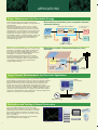
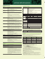
GP-IB Communication (/C1)
Harmonic Measurement (/G5)
GP-IB communication enables you to control the WT500 or transfer
data from a PC.
Ethernet Communication (/C7)
This function enables simultaneous measurement of normal and
harmonic data.
Harmonic components of up to the 50 th order can be measured.
With the WT500 you can simultaneously confirm voltage, current,
and the distortion factor (THD) as well as measure the distortion
factor without switching modes.
Data can be transferred via Ethernet* communication.
It enables file transfers using an FTP server.
*100BASE-TX
Harmonic Dual List
THD measurement
HUB
Delta Computation
Ethernet
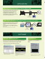
External Current Sensor Input (/EX1, /EX2, /EX3)
Current can be measured by using current clamps without
disconnecting power supply wiring (voltage output type). By setting
an external current sensor conversion ratio, it can support various
types of current clamp-on probes.
This function allows you to calculate individual phase voltages and
phase currents from the line voltages and phase currents measured
in a three-phase, three-wire system. The phase voltage can be
calculated from the line voltage measured with the three-phase,
three-wire (3V3A) method. This is useful when you want to
determine the phase voltage in a DUT with no neutral line by using
the three-phase, three-wire (3V3A) method.
Note: This function cannot be installed on products with only one element.
Added Frequency Measurement (/FQ)
VGA Output (/V1)
By connecting to a monitor, you can create large displays of
numerical values and waveforms. This function is convenient for
simultaneously confirming data on multiple monitors, or to check
data remotely.
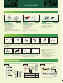
In addition to the standard two channels of frequency
measurement, an option is available for frequency measurement on
all channels. This option provides frequency measurement of
voltage and current on all channels with input elements 1 through 3
installed.
This is necessary when you want to measure voltage and current
frequency from the instrument's I/O as well as voltage and current
frequencies of multiple items under test at the same time.
Note: This function cannot be installed on products with only one input element.
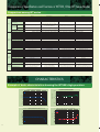
REAR PANEL
Rear Panel
Standard feature
1
5
4
6
8
7
2
3
1 Voltage input terminals
2 Current input terminals
3 USB communication interface
4 External trigger Signal, External clock input Connector
Optional feature
5 External Current Sensor Input Terminals (/EX option)
6 GP-IB communication Interface (/C1 option)
7 Ethernet Port (100BASE-TX)
8 VGA Output (/V1 option)
6