1
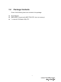
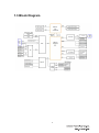
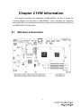
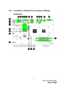
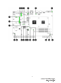
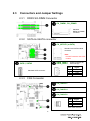
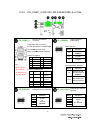
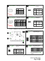
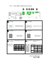
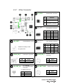
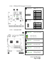
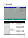
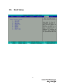
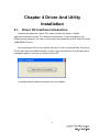
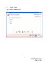
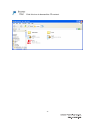
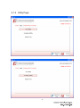
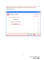
AMB-A55EG1 Board User Manual 1 Copyright All Rights Reserved. Manual’s first edition: For the purpose of improving reliability, design and function, the information in this document is subject to change without prior notice and does not represent a commitment on the part of the manufacturer. In no event will the manufacturer be liable for direct, indirect, special, incidental, or consequential damages arising out of the use or inability to use the product or documentation, even if advised of the possibility of such damages. This document contains proprietary information protected by copyright. All rights are reserved. No part of this Manual may be reproduced by any mechanical, electronic, or other means in any form without prior written permission of the manufacturer. Trademarks AMB-A55EG1 is a registered trademarks of Acrosser; IBM PC is a registered trademark of the International Business Machines Corporation; Ivy Bridge and core TM i is a registered trademark of Intel Technologies Inc; Phoenix is a registered trademark of Phoenix Technologies Ltd,; other product names mentioned herein are used for identification purposes only and may be trademarks and/or registered trademarks of their respective companies. 2 Table of Contents Chapter 1 Introduction ...................................................................................... 5 1.1 Specifications ........................................................................................................... 5 1.2 Package Contents...................................................................................................... 7 1.3 Block Diagram.......................................................................................................... 8 Chapter 2 H/W Information ............................................................................... 9 2.1 Mainboard illustration .............................................................................................. 9 2.2 Locations of IO ports & Jumper settings definition ............................................... 10 2.3 Connectors and Jumper Settings ............................................................................ 12 2.3.1 DDR3 SO-DIMM Connector ..................................................................... 12 2.3.2 SATA & mSATA connector ...................................................................... 12 2.3.3 FAN Connector .......................................................................................... 12 2.3.4 CN_COM1_2 (RS-232 ,RS-232/422/485) & ccTalk ................................. 13 2.3.5 Audio 5.1CH out & 2CH Speaker Out ....................................................... 14 2.3.6 VGA, HDMI, USB & LAN connector ....................................................... 15 2.3.7 Other Connector ......................................................................................... 16 2.3.8 FPGA & PIC firmware Connector ............................................................. 17 2.3.9 Indicated LED ............................................................................................ 17 2.3.10 The Jumper & Switch setting ..................................................................... 18 2.4 Edge Connector Pin Definition .............................................................................. 19 Chapter 3 BIOS Settings ................................................................................. 21 3.1. Main Setup.............................................................................................................. 22 3.2. Advanced Chipset Setup......................................................................................... 24 3.3. AMD Setup ............................................................................................................. 25 3.4. Super IO Setup ....................................................................................................... 28 3.5. Security Setup ......................................................................................................... 31 3.6. Boot Setup .............................................................................................................. 33 3.7. Exit Setup ............................................................................................................... 34 Chapter 4 Driver And Utility Installation ........................................................ 36 4.1. Driver CD Interface Introduction ........................................................................... 36 4.1.1 Driver Page ................................................................................................. 37 4.1.2 Utility Page ................................................................................................. 43 4.1.3 Application Page ........................................................................................ 47 4.1.4 Documents Page ......................................................................................... 48 Chapter 5 Software Installation and Programming Guide ........................... 49 5.1 API List and Descriptions ...................................................................................... 49 3 5.1.1 General Usage ............................................................................................ 49 5.1.2 GPIO ........................................................................................................... 50 5.1.3 PIC .............................................................................................................. 54 5.1.4 SRAM ......................................................................................................... 57 5.1.5 GPO Counter .............................................................................................. 59 5.1.6 GPI Counter ................................................................................................ 60 5.1.7 TIMER ........................................................................................................ 61 5.1.8 Security ....................................................................................................... 62 5.2 Reserved GPI and GPO Info .................................................................................. 66 5.3 GPI and GPO Info and Explanations...................................................................... 68 Chapter 6 FAQ ................................................................................................. 71 Appendix: Technical Support Form ............................................................... 76 4 Chapter 1 Introduction AMB-A55EG1 is an all-in-one gaming system based on AMD most advanced Fusion platform. AMD Fusion APU integrates AMD Radeon HD 6310 graphic controller which provide powerful 2D/3D performance for various gaming S/W. Besides powerful graphic controller, AMB-A55EG1 also integrates gaming control features to satisfy gaming applications, e.g. slot machine and AWP machine. 1.1 Specifications Description AMD Fusion Gaming board Dimension 187 x 268mm CPU AMD Fusion T56N 1.6GHz processor Chipset A55E CPU Thermal FAN with heat sink System Memory Two SO-DIMM, DDR3 up to 8GB. Video 1. 2. Storage 1. Two SATA connectors 2. Two SATA power connector mSATA One mSATA slot Audio 1. 5.1 channel unamplified to box header 2. 6 Watts amplifier for front right, and front left 3. Amplified outputs are connected to 72 pin golden finger LAN 1 x 10/100/1000Mbps LAN with RJ45 connector Serial Ports 1. 2. 3. 4. USB 1 4 x external USB 2.0 ports 2 2 x internal USB 2.0 ports Digital I/O 1 16 x protected digital inputs. (high above 3V, low is 0V) 2 14 x max 500mA MOSFET outputs 3 2 x max 1000mA output for tower lamps VGA1: DB-15 connector for VGA output HDMI connectors for Video output COM 1 is RS-232C COM2 is RS422/485/232C COM3 is 4-pin ccTalk COM4 is 10-pin ccTalk 5 SRAM 1. Battery back up SRAM 2. Dual Bank SRAM (max 1MB, default 256KB) 3. Each SRAM has a clear jumper Keyboard & Mouse Support USB keyboard mouse. Watch dog timer 1 to 255 seconds / minutes programmable Board edge I/O 1. 2. 3. 4. 5. 6. 7. External I/O 36P (72) pin golden finger One RJ45 for LAN 4 x USB 2.0 ports 1x DB15 for VGA1 1x HDMI LED for power and HDD 2 x male DB9 for COM1 & COM2 (RS422/485/232) 4 / 10 pin connector for ccTalk from COM 3 & COM4 Operation System Windows XP (32 bit), Fedora 14 (32 bit), Ubuntu 10.04 (32 bit) Power input 1. DC 12V, 5V +/- 5% for system power from golden fingers 2. AT power mode Operation temperature 0 to 60 Degree Celsius 6 1.2 Package Contents Check if the following items are included in the package. Quick Manual AMB-A55EG1 board (with AMD T56N CPU; but, w/o memory) 1 x manual & Software Utility CD 7 1.3 Block Diagram 8 Chapter 2 H/W Information This chapter describes the installation of AMB-A55EG1. At first, it shows the Function diagram and the layout of AMB-A55EG1. It then describes the unpacking information which you should read carefully, as well as the jumper/switch settings for the AMB-A55EG1 configuration. 2.1 Mainboard illustration 9 2.2 Locations of IO ports & Jumper settings definition 10 11 2.3 Connectors and Jumper Settings 2.3.1 DDR3 SO-DIMM Connector CN_DIMM1, CN_DIMM2 Standard DDR3 SO-DIMM connector 2.3.2 SATA & mSATA connector CN_MPCIE1 (mSATA) Standard mini-SATA module connector Note: Do NOT insert the mini-PCIE module SATA_PWR1 SATA_PWR2 SATA1, SATA2 Standard SATA connector 2.3.3 Power connector for SATA storage PIN Signal 1 2 3 4 +12V GND +3.3V +5V FAN Connector CN_FANSYS1 CN_FANCPU1 CN_FANSYS2 PIN 1 2 3 Signal GND +12V NA 3 Pin, Pitch:2.54mm 12 2.3.4 CN_COM1_2 (RS-232 ,RS-232/422/485) & ccTalk RS-232, RS-422/485 connector CN_COM1_2 D-Sub 9pin Male connector for Standard RS232, RS422/RS485 Up is COM1 (RS232 only) Below is COM2 (RS232/422/485) D-Sub9 for RS232: PIN Signal PIN Signal DCR 1 2 3 4 5 DCD 6 7 8 9 Note: RTS CTS RI Mode setting by JP_COM2S1, PIN JP_422_485S1 6 Signal 1 7 8 9 JP_RS232S1 PIN 2 422 RX422 RX+ Mode selection: Short Function 1-2 RS-232 (Default) 3-4 RS-485 5-6 RS-422 RX TX DTR GND D-Sub9 for RS422/485: JP_RS232S1 & COM2 connector mode setting JP_COM2S1 Signal Terminal resistor selection: Short Function 7-8 RS485 TX with 120ohm terminal (Default) 9-10 RS422 RX with 120ohm terminal 485 RX+/TX+ 422 TX+ 485 RX-/TX422 TX- 3 4 5 COM2 be RS-232 selection COM2 be RS-422/485 JP_422_485S1 selection Short Function Short Function 1-2 3-4 5-6 7-8 9-10 COM2 be RS-232 (Default) 1-2 3-4 5-6 7-8 9-10 COM2 be RS-422/485 13 CN_CCTALK1 Note: Vs setting by JP_VCCTALK1 ccTalk Type-5 connector PIN Signal Short Function 1 2 3 4 +Vs 0V /DATA 1-2 +12V (Default) 2-3 +24V Please reference to ccTalk-Generic-Specification-v4.6 CN_CCTALK2 ccTalk Type-7 connector PIN Signal CN_CCTALK2 JP_VCCTALK2 Vs setting PIN Signal 1 /DATA 2 GND 3 NC 4 NC 5 NC 6 NC 7 +Vs 8 0V 9 NC 10 NC Please reference to ccTalk-Generic-Specification-v4.6 Note: Vs setting by JP_VCCTALK2 2.3.5 CN_CCTALK1 JP_VCCTALK1 Vs setting Short Function 1-2 +12V (Default) 2-3 +24V Audio 5.1CH out & 2CH Speaker Out CN_AUDI 5.1CH Audio out connector (Without Amplifier) O1 PIN Signal PIN 1 Front Out L 2 3 GND 4 5 Surround L 6 7 GND 8 9 Center 10 Signal Front Out R GND Surround R GND Subwoofer 2x5Pin, Pitch:2.54mm Speaker with 6W Amplifier selection JP_AMP1 Short Function 1-3 2-4 3-5 4-6 With Amplifier (Default) 2CH Speaker output JAMMA1 on edge connector PIN Signal PIN Signal A2 Speaker L B2 GND A3 Speaker R B3 GND Note: Through amplifier or w/o Amplifier depend on JP_AMP1 setting. Without Amplifier 14 2.3.6 VGA, HDMI, USB & LAN connector CN_VGA1 CN_HDMI1 Standard VGA connector (D-Sub 15pin connector) CN_USB2 CN_USB1 CN_USB3 Standard HDMI connector (Optional) Standard USB 2.0 Standard USB 2.0 Type-A connector Type-A connector Onboard USB 2.0 connector CN_USBLA RJ45 LAN & USB 2.0 connector N1 LAN LED table: PIN Signal PIN Signal 1 3 5 7 9 +5V 2 4 6 8 10 +5V DATA1 DATA 1+ GND NC LED DATA2 DATA2 + LED1 GND NC Header 2X5pin, Pitch: 2.54mm 15 LED2 ON/OFF Status OFF 10Mbps Green 100Mbps Orange 1000Mbps Yellow Link/Active OFF LAN OFF 2.3.7 Other Connector JP_FPIO1 Reset Button connector PIN Function 1-2 (Reserved) 3,4 (Reserved) 5,6 Reset button connector SPI_CN1 SPI Interface connector (Optional) PIN 1 3 5 7 9 CN_BAT1 CR2032 Battery socket for system RTC Case open Log switch PIN 2 4 6 8 10 Signal +3.3V HOLD# CLK MOSI NC LPC Interface connector (Optional) PIN Signal 1 CLK 3 RST# 5 FRAME# 7 AD3 9 AD2 CR2032 3V battery socket DOOR_SW_1 CN_LPC1 Signal CS# MISO WP# GND NC DOOR_SW_2 PIN 2 4 6 8 10 Signal AD1 AD0 +3.3V GND GND External Log input connector SW Event 1-2 Signal Push Release Non-case open Case opening Open Short No event Event input 3.7V 500mAh Re-chargeable battery connector CN_BAT_A1 CN_IBUTTONB1 iButton signal connector for SRAM & Security. PIN Signal 1 2 3.7~4.2V GND 16 PIN Signal 1 2 I/O Data GND 2.3.8 FPGA & PIC firmware Connector CN_FPGA1 (Reserved) CN_PIC1 (Reserved) 2.3.9 FPGA firmware recoded Header PIN Signal 1 2 3 4 5 6 7 8 3.3V VCC TDO TDI (NC) (NC) TMS GND TCK PIC firmware recoded Header PIN Signal 1 2 3 4 5 3V VCC ISPDATA ISPCLK ISPVPP GND Indicated LED LED_GY1 System status indicated Green: Power ON Yellow: HDD active 17 LED_5V1 5V Power IN LED LED_24V1 24V Power IN LED LED_12V1 12V Power IN LED LED_CHG1 Battery charging LED ON: Battery charging 2.3.10 The Jumper & Switch setting JP_CCMOS1 Short Function 1-2 Normal (Default) 2-3 Clear CMOS JP_SRAM1 SRAM1 data clear Short Function 1-2 Not clear (Default) 2-3 SRAM Clear JP_SRAM2 SRAM1 data clear (Reserved) SW-FPGA1 No 1 OFF/O OFF ON 2 OFF ON 3 OFF ON 4 Mode N OFF ON 1-2 2-3 Function 1-2 Not clear (Default) 2-3 SRAM Clear No KEYIN_METER MOSFET OFF 1 (Default) METER OUT setting 2 & HOPPER SSR setting OFF KEYIN_METER MOSFET ON KEYOUT_METER OFF MOSFET 2 OFF (Default) 3 (Default) 4 (Default) Pull down (Default) HOPPER_SSR Pull up 18 HOPPER_SSR MOSFET OFF (Default) (Default) ON (Reserved) OFF (Default) ON (Reserved) JP_CLAMP1 HOPPER_SSR PAYOUT_METER MOSFET ON OFF BILLIN_METER MOSFET ON Function (Default) HOPPER_SSR MOSFET ON COININ_METER MOSFET ON BILLIN_METER MOSFET OFF PAYOUT_METER MOSFET OFF ON KEYOUT_METER MOSFET ON COININ_METER MOSFET OFF Mode OFF/ON ON JP_METER1 (Reserved) Short Short SW-FPGA2 METER OUT setting 1 Clear CMOS Edge connector GPO pins Clamping voltage setting Short Function 1-2 +12V (Default) 2-3 +24V 2.4 Edge Connector Pin Definition IPH: Input (with Internal Pull High & without isolated) (only support GND & Open signal) OD: Open Drain Output (Maximum external voltage: 24V DC) AO: Analog Output I/O: Spare Input/Output (5V tolerance) P: Power Empty: Reserved Component Side (A) Solder Side (B) Function I/O Type Pin Pin I/O Type Function GND P A1 B1 P GND GND P A2 B2 P GND Power +5V P A3 B3 P Power +5V Power +5V P A4 B4 P Power +5V Power +12V P A5 B5 P Power +12V Power +12V P A6 B6 P Power +12V Power +24V P A7 B7 P Power +24V A8 B8 GND P A9 B9 P GND GND P A10 B10 P GND 19 Component Side (A) Function Pin Pin I/O Type Function A1 B1 AO A2 B2 AO Audio Ground Right Speaker AO Button 1 IPH A3 B3 AO Audio Ground A4 B4 Button 2 IPH A5 B5 Button 3 IPH A6 B6 Button 4 IPH A7 B7 Button 5 IPH A8 B8 Button 6 IPH A9 B9 Button 7 IPH A10 B10 Button 8 IPH A11 B11 Button 9 IPH A12 B12 A13 B13 A14 B14 A15 B15 A16 B16 A17 B17 A18 B18 Left Speaker Coin-IN Signal A I/O Type Solder Side (B) IPH Coin-IN Signal B IPH A19 B19 Button 10 IPH A20 B20 IPH Button 13 Button 11 IPH A21 B21 IPH Button 14 GND P A22 B22 IPH Hopper Sensor Key-IN Meter (500mA max) OD A23 B23 Bill-IN Meter (500mA max) OD A24 B24 Coin-IN Meter (500mA max) OD A25 B25 Pay-OUT Meter (500mA max) OD A26 B26 Key-OUT Meter (500mA max) OD A27 B27 A28 B28 Lamp1 (500mA max) OD A29 B29 OD Lamp7 (1A max) Lamp2 (500mA max) OD A30 B30 OD Lamp8 (500mA max) Lamp3 (500mA max) OD A31 B31 OD Lamp9 (500mA max) Lamp4 (500mA max) OD A32 B32 OD Lamp10 (500mA max) Lamp5 (500mA max) OD A33 B33 OD Hopper SSR (500mA max) Tower Lamp6 (1A max) OD A34 B34 Button 12 IPH A35 B35 GND P A36 B36 P GND 20 Chapter 3 BIOS Settings This chapter describes the BIOS menu displays and explains how to perform common tasks needed to get the system up and running. It also gives detailed explanation of the elements found in each of the BIOS menus. The following topics are covered: Main Setup Advanced Chipset Setup AMD Setup Super IO Setup Security Setup Boot Setup Exit Setup 21 3.1. Main Setup Once you enter the Phoenix BOS™ CMOS Setup Utility, the Main Menu will appear on the screen. Use the arrow keys to highlight the item and then use the < + > < - > keys to select the value you want in each item. Note: Listed at the bottom of the menu are the control keys. If you need any help with the item fields, you can press the <F1> key, and it will display the relevant information. Option Choice Description System Date N/A System TIme N/A Set the system time. Processor Type N/A This item displays the CPU type. Processor Speed N/A This item displays the CPU speed Set the system date. Noted that the “Day” automatically changes when you set the date. 22 System Memory N/A This item displays the memory speed. L2 Cache RAM N/A This item displays the L2 cache memory size. Total memory N/A This item displays the memory size that used. N/A This item displays the memory size that used on slot 0. N/A This item displays the memory size that used on slot 1. BIOS version N/A This item displays the system BIOS version. Build Date N/A This item displays the BIOS build date. Speed Memory Channel Slot0 Memory Channel Slot1 23 3.2. Advanced Chipset Setup Option Quick Boot Choice Description Enabled Allows the system to skip certain tests while booting. This Disabled will decrease the time needed to boot the system. Full Screen Logo Enabled Show Disabled Displays the full screen logo upon BIOS booting. 24 3.3. AMD Setup 25 26 Option Choice Description Enabled --- Enables onboard controller if audio device is Azalia Option Enabled detected Disabled Disabled --- Turn off onboard controller to allow external controller OnChip SATA Enabled Enabled --- Enable onboard SATA controller Channel Disabled Disabled --- Turn off onboard SATA controller AHCI OnChip SATA Type Legacy IDE N/A AHCI ID4394 Integrated Graphics Auto Force Auto --- Onboard VGA Frame Buffer Size by the Main memory size Force --- set fixed Onboard VGA Frame Buffer Size Auto 32M 64M UMA Fram Buffer Size 128M 256M Select Onboard VGA Frame Buffer Size 384M 512M 1G 2G 27 3.4. Super IO Setup 28 29 Option Choice Description Disabled 3F8/IRQ4 Serial Port 1/2/3/4 2F8/IRQ3 338/IRQ5 Sets the base I/O port address and IRQ for the onboard device 238/IRQ11 These read-only fields show the functions of the hardware CPU Temperature N/A thermal sensor by CPU thermal diode that monitors the chip blocks to ensure a stable system. System Temperature N/A Show you the current system temperature. CPU Fan Speed N/A Show you the CPU Fan Speed. SYS Fan 1/2 Speed N/A Show you the System Fan1/2 Speed. CPU VCore N/A Show you the voltage of Vcore 40 CPU Target Temp 50 N/A 60 CPU Fan Mode Full Speed Full: Fan Speed full on 30 3.5. Security Setup Option Choice Description The BIOS attempts to load the operating Supervisor Password is N/A system from the devices in the sequence selected in these items. When a password has been enabled, you will be prompted to enter your password every time you try to enter Setup. This prevents unauthorized persons from Set Supervisor Password Pressing <Enter> on this item for confirmation: ENTER PASSWORD: changing any part of your system configuration. Type the password, up to eight characters in length, and press <Enter>. The password typed now will clear any previous password from the CMOS memory. You will be asked to confirm the password. Type the password again and 31 press <Enter>. You may also press <Esc> to abort the selection and not enter a password. To disable a password, just press <Enter> when you are prompted to enter the password. A message will confirm that the password will be disabled. Once the password is disabled, the system will boot and you can enter Setup freely. 32 3.6. Boot Setup 33 3.7. Exit Setup option Exit Saving Changes Exit Discarding Changes Load Setup Defaults Discard Changes Choice Description Pressing <Enter> on this item Exit BIOS Setup and Save Changes BIOS for confirmation: Setting. Pressing <Enter> on this item Exit BIOS Setup and Without Save Changes for confirmation: BIOS Setting. Pressing <Enter> on this item for confirmation: Restore/Load Default values for all the setup options. Pressing <Enter> on this item for confirmation: 34 System will not save any BIOS changes. Save Changes Pressing <Enter> on this item Save Changes BIOS Setting but without exit for confirmation: BIOS Setup. 35 Chapter 4 Driver And Utility Installation 4.1. Driver CD Interface Introduction Acrosser provides the a driver CD, which includes the drivers, utilities, applications and documents. For Windows environment, it can be guided by the following setup program; for Linux environment, the related files can be found at folder “AMB-A55EG1\Linux”. Once putting the CD into the optical disk drive, it will run automatically. The driver CD will also detect the MB information to see if they are matched. The following error messages appear if you get an incorrect driver CD. It indicates that the board information is not available. 36 4.1.1 Driver Page This is the Driver Installation Page. 37 Click the icon, all the drivers will be selected. 38 Click the icon, all selected items will be cleared. 39 Click the icon to install the selected drivers. The progress bar shows up. When installation finished, the main window will temporarily disappear. 40 Please click ‘Yes’ to restart the system 41 Click this icon to browse this CD content. 42 4.1.2 Utility Page 43 Before launching this utility, users have to install the ‘Acrosser Driver’ in advance. The system may ask for installing other libraries. You can find the libraries on the ‘Application’ page also. 44 Before you launch “test utility”, please execute “createkey utility”. Else, some tests could have incorrect results. This is Test Utility. This is CerateKey Test Uility. 45 Users can double click the ‘Sample Code’ to open the sample code folder. The source code of the test utility is in this folder. 46 4.1.3 Application Page 47 4.1.4 Documents Page Double click on one of the items to open the user manual or technical support form. The form is written by Microsoft Word format. If you have any questions, you can fill the form and send back Acrosser for help. 48 Chapter 5 Software Installation and Programming Guide AMB-A55EG1 is an All-in-One gaming control box based on AMD Fusion (G series) T56N platform. In order to ease the customer’s operation on A55EG1, Acrosser provides device driver, application interface (API), and source code of demo application. The provided software is available on both Windows and Linux. The detailed S/W SPEC are described in Chapter 1. All the provided software is located on the bundled disc. 5.1 API List and Descriptions The following info describes the details of the provided API function. 5.1.1 General Usage 5.1.1.1 ♦ lib_init Description This function is used to register the FPGA related resource. FPGA has to be registered by this function before other functions are called. ♦ Syntax int lib_init (void) ♦ Argument ♦ Return 5.1.1.2 ♦ None 0: Successful, -1: Fail, 1:Can’t find key. lib_close Description This function is used to release the resource of FPGA. ♦ Syntax void lib_close(void) ♦ Argument None 49 ♦ Return 5.1.1.3 ♦ None get_fpga_Fd Description Get file descriptor number. ♦ Syntax int get_fpga_Fd (void) ♦ Argument ♦ None Return File descriptor number. 5.1.2 GPIO 5.1.2.1 ♦ get_gpo_lines Description Get how many gpo pins in this product. ♦ Syntax int get_gpo_lines(void) ♦ Argument ♦ Return 5.1.2.2 ♦ None Total gpo pins number. get_gpi_lines Description Get how many gpi pins in this product. ♦ Syntax int get_gpi_lines(void) ♦ Argument ♦ None Return Total gpi pins number. 50 5.1.2.3 ♦ get_gpo_status Description Get current gpo pin status. ♦ Syntax int get_gpo_status(int pin) ♦ Argument ♦ Return 1: ON 0: OFF 5.1.2.4 ♦ pin: int type, the range is 0-31. get_gpi_status Description Get current gpi pin status. ♦ Syntax int get_gpi_status(int pin) ♦ Argument ♦ Return 1: ON 0: OFF 5.1.2.5 ♦ pin: int type, the range is 0-31. set_gpo Description Set gpo pin status. ♦ Syntax void set_gpo(int pin, int value) ♦ ♦ Argument pin: int type, the range is 0-31. value: 1: ON , 0: OFF Return None 51 5.1.2.6 ♦ set_gpi_debounce Description Set gpi pin debounce (default 16ms). ♦ Syntax int set_gpi_debounce(int pin, int debounce) ♦ ♦ Argument pin: int type, the range is 0-31. debounce: int type, the range is 1-255(ms). Return 0: Success. -1:Fail. 5.1.2.7 ♦ get_gpi_debounce Description Get gpi pin debounce. ♦ Syntax int get_gpi_debounce(int pin) ♦ Argument ♦ Return 5.1.2.8 ♦ pin: int type, the range is 0-31. debounce time value. set_gpi_interrupt Description Set gpi pin interrupt Enable or Disable. ♦ Syntax void set_gpi_interrupt(int pin, int value) ♦ ♦ Argument pin: int type, the range is 0-31. value: 0: Disable, 1:Enable Return None 52 5.1.2.9 ♦ set_allgpi_interrupten Description Set gpi (0-31) pin interrupt Enable. ♦ Syntax void set_allgpi_interrupten(void) ♦ Argument ♦ Return 5.1.2.10 ♦ None (Delay 16 sec) to return None set_allgpi_interuptdn Description Set gpi (0-31) pin interrupt Disable. ♦ Syntax void set_allgpi_interruptdn(void) ♦ Argument ♦ Return 5.1.2.11 ♦ None (Delay 16 sec) to return None get_gpi_interrupt_status Description Get gpi pin interrupt status. ♦ Syntax int get_gpi_interrupt_status(int pin) ♦ Argument ♦ pin: int type, the range is 0-31. Return 0: Disable 1: Enable 53 5.1.2.12 ♦ getSIGNAL_IN_status Description Get SIGNAL_IN status. ♦ Syntax int getSIGNAL_IN_status(int pin) ♦ Argument ♦ Return 0: Low 1: High 5.1.2.13 ♦ pin: int type, the range is 0-7. getDIP_SW_status Description Get DIP Switch status. ♦ Syntax int getDIP_SW_status(int pin) ♦ Argument ♦ pin: int type, the range is 0-7. Return 0: Low 1: High 5.1.3 PIC 5.1.3.1 get_rtc ♦ Description Get rtc time data structure. ♦ Syntax int get_rtc(struct tm *pTm) ♦ Argument ♦ pTm: Time structure tm pointer to save rtc data. Return 0:Successful 54 5.1.3.2 ♦ -1: Fail set_rtc Description Set rtc time. ♦ Syntax int set_rtc(unsigned char *pwd, struct tm *ptm) ♦ ♦ Argument pwd: unsigned char pointer to transfer password. (00000000) ptm: Time structure tm pointer to set rtc data. Return 0:Successful -1: Fail 5.1.3.3 ♦ get_DoorSWLog Description Get Door High -> Low and Low->High Switch Log. Please Note: event 3 and 4 not real hardware. ♦ Syntax int get_DoorSWLog(int event, struct tm *ptm, struct tm *ptm1) ♦ ♦ 5.1.3.4 ♦ Argument event: int type, which log the range is 1-8. ptm: Time structure tm pointer to save High ->Low time data. ptm1: Time structure tm pointer to save Low ->High time data. Return 0:Successful -1: Fail clr_DoorSWLog Description Clean one Switch Log. ♦ Syntax int clr_DoorSWLog(unsigned char *pwd, int event) Please Note: event 3 and 4 not real hardware. ♦ Argument 55 ♦ pwd: unsigned char pointer to transfer password. (00000000). event: int type, which log to clean the range is 1-8. Return 0:Successful -1: Fail 5.1.3.5 ♦ get_batlog Description Get battery Low Log. ♦ Syntax int get_batlog (struct tm *pTm) ♦ Argument ♦ Return 0:Successful -1: Fail 5.1.3.6 ♦ pTm: Time structure tm pointer to save berry low time data. clr_batlog Description Clean battery Low Log. ♦ Syntax int clr_batlog(unsigned char *pwd) ♦ Argument ♦ Return 0:Successful -1: Fail 5.1.3.7 ♦ pwd: unsigned char pointer to transfer password. (00000000). getDOOR_SW_status Description Get DOOR_SW status. ♦ Syntax int getDOOR_SW_status(int pin) ♦ Argument pin: int type, the range is 1-8. 56 ♦ Return 0:Low 1: High 5.1.4 SRAM 5.1.4.1 ♦ getSramSize Description Get Sram Size. ♦ Syntax unsigned int getSramSize(void) ♦ Argument ♦ Return 5.1.4.2 ♦ None. Unsigned int type, Sram Size / 1024 (Kbytes) getSramByte Description Read Particular an address current byte data. ♦ Syntax unsigned char getSramByte(unsigned long addr) ♦ Argument ♦ Return 5.1.4.3 ♦ addr: unsigned long type, Particular an address. Unsigned char type for particular address current data. setSramByte Description Write Particular byte data on Particular an address. ♦ Syntax void setSramByte(unsigned long addr, unsigned char data) ♦ ♦ Argument addr: unsigned long type, Particular an address. data: unsigned char type, Particular an data. Return 57 5.1.4.4 ♦ None. getSramWord Description Read Particular an address current Word data. ♦ Syntax unsigned short getSramWord(unsigned long addr) ♦ Argument ♦ Return 5.1.4.5 ♦ addr: unsigned long type, Particular an address. Unsigned short type for particular address current data. setSramWord Description Write Particular Word data on Particular an address. ♦ Syntax void setSramWord(unsigned long addr, unsigned short data) ♦ ♦ Argument addr: unsigned long type, Particular an address. data: unsigned short type, Particular an data. Return 5.1.4.6 ♦ None. getSramDword Description Read Particular an address current Double Word data. ♦ Syntax unsigned int getSramDword(unsigned long addr) ♦ Argument ♦ Return 5.1.4.7 ♦ addr: unsigned long type, Particular an address. Unsigned int type for particular address current data. setSramDword Description Write Particular Double Word data on Particular an address. ♦ Syntax 58 void setSramDword(unsigned long addr, unsigned int data) ♦ ♦ Argument addr: unsigned long type, Particular an address. data: unsigned int type, Particular an data. Return None. 5.1.5 GPO Counter 5.1.5.1 ♦ startgpocounter Description Start an GPO Counter. ♦ Syntax int startgpocounter(int counter, unsigned short counter_value, int clk) ♦ ♦ Argument counter: int type, Particular an counter (0-7). counter_value: unsigned short type, Particular counter_value (1-65535). clk: 0: 1K HZ, 1: 10 HZ. Return 0:Successful. -1: Fail. 5.1.5.2 ♦ reloadgpocounter Description Reset an pause GPO Counter to new Counter value and start Counter. ♦ Syntax int reloadgpocounter(int counter, unsigned short counter_value) ♦ ♦ Argument counter: int type, Particular an counter (0-7). counter_value: unsigned short type, Particular counter_value (1-65535). Return None 59 5.1.5.3 ♦ getgpocountervalue Description Get an GPO Counter Current Counter value. ♦ Syntax unsigned short getgpocountervalue(int counter) ♦ Argument ♦ Return 5.1.5.4 ♦ counter: int type, Particular an counter (0-7). unsigned short type, Current Counter value. stopgpocounter Description Stop an GPO Counter. ♦ Syntax void stopgpocounter(int counter) ♦ Argument ♦ counter: int type, Particular an counter (0-7). Return None. 5.1.6 GPI Counter 5.1.6.1 ♦ startgpicounter Description Start an GPI Counter. ♦ Syntax int startgpicounter(int counter, unsigned short comp_value, int mode, int timeout, int timeclk) ♦ Argument counter: int type, Particular an counter (1-4). comp_value: unsigned short type, Particular an compare value (0-65535), 0:Doesn’t compare. mode: int type, set counter mode, 0: rise edge, 1: fall edge, 2:both. timeout: int type, set time out value (1-31). timeclk: int type, 0: 0.01Hz(100s), 1: 0.1Hz(10s), 2: 1Hz(1s), 60 3: 10Hz(0.1s), 4: 100Hz(0.01s), 5: 1KHz(1ms), 6: 10KHz(0.1ms), 7: 100KHz(0.01ms) ♦ Return 0:Successful. -1: Fail. 5.1.6.2 ♦ getgpicountervalue Description Get an GPI Counter Current Counter value. ♦ Syntax unsigned short getgpicountervalue(int counter, int mode) ♦ Argument counter: int type, Particular an counter (1-4). mode: unsigned short type, 0: Read Counter Value and Don't Clean 1: Read Counter Value and Clean. ♦ Return 5.1.6.3 ♦ unsigned short type, Particular an counter value. stopgpicounter Description Stop an GPI Counter. ♦ Syntax void stopgpicounter(int counter) ♦ Argument ♦ counter: int type, Particular an counter (1-4). Return None. 5.1.7 TIMER 5.1.7.1 startimer ♦ Description Start an Particular Timer. ♦ Syntax int startimer(int timer, unsigned short time_value, int mode, int clk) 61 ♦ ♦ Argument timer: int type, Particular an timer (0-3). time_value: unsigned short type, Particular an time value (1-65535). mode: int type, 0: Simple Timer, 1: Cycle Timer. clk: int type, 0: 1us. 1: 1ms, 2: 1s. Return 0:Successful. -1: Fail. 5.1.7.2 ♦ getimervalue Description Read an Particular Timer Current timer value. ♦ Syntax unsigned short getimervalue(int timer) ♦ Argument ♦ Return 5.1.7.3 ♦ timer: int type, Particular an timer (0-3). unsigned short type, an Particular Timer Current timer value. stoptimer Description Stop an Particular Timer. ♦ Syntax void stoptimer(int timer) ♦ Argument ♦ timer: int type, Particular an timer (0-3). Return None. 5.1.8 Security AMB-A55EG1 has the following security API which can be implemented into customer’s S/W. If customers want to setup their own security certifications, please reconfirm with our engineers whether the system support it or not. 62 5.1.8.1 get_trusted_key ♦ Description Read Current Security Trust Key. ♦ Syntax int get_trusted_key(unsigned char *data) ♦ Argument ♦ Return 0:Successful. -1: Fail. 5.1.8.2 ♦ data: unsigned char pointer to save Security Trust key data. read_iButton_key Description Read Current Security iButton Key. ♦ Syntax int read_iButton_key(int btn, unsigned char *data) ♦ Argument btn: 1:first ibutton. ♦ Return 0:Successful. -1: Fail. 5.1.8.3 ♦ data: unsigned char pointer to save Security ibutton key data. get_trusted_mode Description Read Current Security Lock mode. ♦ Syntax int get_trusted_mode(unsigned char *mode) ♦ Argument mode: unsigned char pointer to save mode data. (0 : Trust Lock Test, 0xFF: Disable Trust Lock Test, 0xA5: Trust Lock True) ♦ Return 0:Successful. -1: Fail. 63 5.1.8.4 ♦ set_trusted_mode_disable Description Set Security Lock Test mode to disable. ♦ Syntax int set_trusted_mode_disable(void) ♦ Argument None. ♦ Return 0:Successful. -1: Fail. 5.1.8.5 ♦ set_trusted_mode_locktest Description Set Security Lock Test mode, This mode just let you try lock mode. Under This mode, You will can’t get any key information. ♦ Syntax int set_trusted_mode_locktest(void) ♦ Argument None. ♦ Return 0:Successful. -1: Fail. 5.1.8.6 ♦ set_trusted_mode_lock Description Set Security Lock mode, This mode it’s true lock. Under This mode, You will can’t get any key information. ♦ Syntax int set_trusted_mode_lock(void) ♦ Argument None. ♦ Return 0:Successful. -1: Fail. 64 5.1.8.7 ♦ check_trusted_key Description Check Security Trust key, It’s True or Fail. Fail: System will Turn Off. ♦ Syntax void check_trusted_key(unsigned char *data) ♦ Argument ♦ Return 5.1.8.8 ♦ data: unsigned char pointer to transfer Security Trust key to Compare. None. set_trusted_key Description User define trusted key to Set, unsigned char arrary 8 bytes. ♦ Syntax int set_trusted_key(unsigned char *data) ♦ Argument ♦ data: unsigned char pointer to transfer Security Trust key to Set. Return 0:Successful. -1: Fail. 65 5.2 Reserved GPI and GPO Info Channel Gaming I/O Remark GPI 0 BUTTON 1 GPI 1 BUTTON 2 GPI 2 BUTTON 3 GPI 3 BUTTON 4 GPI 4 BUTTON 5 GPI 5 BUTTON 6 GPI 6 BUTTON 7 GPI 7 BUTTON 8 GPI 8 BUTTON 9 GPI 9 BUTTON 10 GPI 10 BUTTON 11 GPI 11 BUTTON 12 GPI 12 BUTTON 13 GPI 13 BUTTON 14 GPI 14 Reserve GPI 15 Reserve GPI 16 Coin_IN_Signal_A GPI 17 Coin_IN_Signal_B GPI 18 Reserve GPI 19 Hopper_Sensor GPI 20 Reserve Signal_IN_5 GPI 21 Reserve Signal_IN_6 GPI 22 Reserve Signal_IN_7 GPI 23 Reserve Signal_IN_8 GPI 24 Reserve Door_SW_A GPI 25 Reserve Door_SW_B GPI 26 Reserve Door_SW_C GPI 27 Reserve Door_SW_D GPI 28 Reserve GPI 29 Reserve GPI 30 Reserve Door_SW_3 GPI 31 Reserve Door_SW_4 iButton2 Reserve I_Button_2 Signal_IN_3 & GPI_18 COUNTER 66 Channel Gaming I/O Remark GPO 0 Lamp 1 GPO 1 Lamp 2 GPO 2 Lamp 3 GPO 3 Lamp 4 GPO 4 Lamp 5 GPO 5 Lamp 6 GPO 6 Lamp 7 GPO 7 Lamp 8 GPO 8 Lamp 9 GPO 9 Lamp 10 GPO 10 reserve GPO 11 reserve GPO 12 reserve GPO 13 reserve GPO 14 reserve GPO 15 reserve GPO 16 Key_IN_meter General purpose GPO GPO 17 Key_OUT_meter General purpose GPO GPO 18 Coin_IN_meter General purpose GPO GPO 19 Bill_IN_meter General purpose GPO GPO 20 Pay_OUT_meter General purpose GPO GPO 21 Hopper_SSR General purpose GPO GPO 22 Reserve GPO_22 COUNTER & DIP_SW_6 GPO 23 reserve GPO_23 COUNTER & DIP_SW_7 GPO 24 reserve GPO 25 reserve GPO 26 reserve GPO 27 reserve GPO 28 reserve GPO 29 reserve GPO 30 reserve GPO 31 reserve 67 5.3 GPI and GPO Info and Explanations Output (GPO) clamp protection reference circuit (clamp voltage jumper can select 12V or 24V) Example: 68 69 Input (GPI) reference circuit: Example: 70 Chapter 6 FAQ Do AMB-A55EG1 support mini-PCIe module? Sorry, AMB-A55EG1 does not support mini-PCIe. The expansion slot is designed for m-SATA use only. Does my system support Windows 7 or 8? The system is designed and verified with Windows XP, Fedora 14 and Ubuntu 10. But, we did not verify this system with Windows 7 or 8. Please check with Acrosser local sales rep. or authorized channels who will help you to confirm whether we have provided new Windows 7 or 8 driver. When AMB-A55EG1 has 2~3 HDDs, why Windows XP install to the wrong HDD? AMB-A55EG1 can equip with 2~3 HDDs to install your Windows XP and applications. If your system has Windows XP installation questions, please refer to Microsoft technical support web site “ http://support.microsoft.com/kb/313348/en-us”. Or, please contact Acrosser FAE for help. Why do we get error message when we execute AMB-A55EG1 utility program? 1. Make sure all the drivers have been installed correctly. (refer to Chapter 4.1.2) 2. Make sure the “createkey utility” has been installed correctly. 3. If the problem did not solve, please contact Acrosser FAE or authorized channels. What can I do if my system does not power on? If your system can not power on via adapter, below are a few steps you can follow to attempt to correct the issue. • Ensure that the power cord and AC adapter are plugged solid and not loose fitting. • Ensure the adapter output is DC 12V (min. 60W) • Ensure the DC 12V output correctly connect to the system. • Attempt to use a different electrical outlet or a different adapter. If your system can not power on via ATX PSU, below are some steps you can fellow to attempt to correct this problem. • ATX PSU has some protections. Ensure that PSU PS_ON# signal connect to GND and the PSU output DC 12V to the system. • Because the system only use DC 12V, it will not consume 3.3V and 5V output. Some PUSs could mis-judge the situations and stop any voltage output. • Ensure the DC 12V output correctly connect to the system. • Attempt to use a different electrical outlet or a different PSU. 71 No display when power on? 1. Make sure all cables are connected well and the power is on: 2. Short clear CMOS jumper to reset CMOS, then reboot the system 3. If the problem did not solve, please Keep the necessary components (e.g. CPU, memory, keyboard and HDD) to test: 4.1 If the system could power on well with the above configuration, please plug the other components back one by one to find out which one may cause this problem. 4.2 4.2.1 4.3 If the system still could not power on, please check your memory. Memory issue: A. Clean the Golden Finger of memory B. Clean the memory slots C. Leave only one memory stick to test D. If convenient, please change different memory modules to test again If the problem did not solve, please contact Acrosser FAE or authorized channels. Where is the serial number located on my system? The serial number (S/N) is an alpha-numeric character located on the bottom or side chassis. (reference only) How do I connect the second monitors to my system? 1. Basically, there are “duplicate” and “extend” mode for the second monitor. A. duplicate mode –- you will see the same contents on both monitors. B. extend mode – your monitors display different contents, and you can drag your contents between the first and second monitor. 2. Ensure the display device setting is correct and monitor cables are connected well. A. For device setting, it could be different because of different operating systems and S/W version B. 3. You can search from “Google” as reference setting. If the problem did not solve, please contact Acrosser FAE or authorized channel. My system has audio problem? If your system has audio problem, below are a few steps you can follow to attempt to correct the issue. 72 • Ensure that the BIOS enable on-board audio function (reference diagram) . • Ensure the audio driver and device has been installed successfully. • Ensure speaker connect to the right connector. • Sometimes, audio has been set “MUTE”. Please adjust the audio volume louder. • If the problem persists, please contact Acrosser FAE or local authorized channel. My system can not connect to internet? If your system can not connect to internet, below are a few steps you can follow to attempt to correct the issue. • Ensure that network adapter can be recognized in Device Manager 73 • If there is question mark or exclamation mark in the network adapter, please re-install your OS and network driver. If the problem did not solve, please contact your local FAE or sales rep for tests. • Ensure the Network Connections/Local Area Connection is enabled (right click and choose “Enable”). If the problem persists, please turn off firewall and anti-virus S/W. If the problem still exists, please contact local FAE or service center for tests. 74 • If the Network Connections/Local Area Connection is showed “limited connection” (yellow exclamation mark), please disable and enable your connection to fix this problem. Or, you can unplug and plug the LAN cable to fix the problem. If the problem still persists, please contact your MIS whether there are any DHCP or IP configuration or ISP/WAN setting limitation. 75 Appendix: Technical Support Form We deeply appreciate you purchase Acrosser products. Please find “tech_form.doc” file in our utility CD. If you have any questions or problems about Acrosser products, please fill in the following information: We will answer your questions a.s.a.p. 1) Describe your info and system info A. Your company name: _____________ B. Your contact info: _________________ & phone number: _________________ C. Your e-mail address: ______________________ D. Your company address: ___________________________________________ __________________________________________ E. Acrosser model name: _____________________ F. Acrosser Serial Number: _____________________ 2) Describe system configuration A. CPU ________________ B. Memory size ___________________ C. Storage (e.g. HDD or CF or SSD) ___________________ D. Extra peripherals (e.g. graphic card) __________________________ E. Operating system & version (e.g. Windows 7 embedded) __________________ F. Special API or driver _________________ (If yes, please provide it for debug,) G. Running applications _____________________ H. Other _________________________ 3) Describe your problems or questions: 4) Send the above info to one of the following Acrosser contact windows: A. Acrosser local Sales Rep B. Acrosser authorized channels C. Acrosser e-mail window --- http://www.acrosser.com/inquiry.html or [email protected] D. Acrosser FAX number --- 886-2-29992887 76 Acrosser Headquarters 新北市三重區重新路五段609巷12號10樓 10F., No.12, Lane 609, Sec. 5, Chongsin Rd., Sanchong District, New Taipei City 241, Taiwan, R.O.C. TEL: +886-(0)2-2 9999 000 FAX: +886-(0)2-2999-2887 [email protected] Acrosser Taichung Office 台中市南屯區河南路四段162號12樓之6 12-6, No.162, Sec. 4, Henan Rd., Nantun Dist., Taichung City 408, Taiwan R.O.C. TEL: +886-(0)4-2251-0659 FAX: +886-(0)4-2254-6079 Acrosser China Subsidiary 欣扬通电子有限公司 深圳分公司 深圳市福田区车公庙泰然九路21号 皇冠科技园3栋2楼东面A区 (邮编:518040) A East 2F 3th Building, Crown Estate No.21, 9 Tai-Ran Road, Che Gong Miao, Futian Dist, Shenzhen, China (Postal:518040) TEL :+86-0755-83542210/2230/2240/2250/2260 FAX :+86-0755-83700087 Acrosser Shanghai Office 欣扬通电子有限公司 上海分公司 上海市徐汇区零陵路631号爱乐大厦12E (邮编:200085) 12E, Aile Building, No.631, Ling-ling Road, Xu-hui Dist, Shanghai, China (Postal:200085) TEL :+86-021-64288853 FAX :+86-021-64288854 Acrosser Beijing Office 欣扬通电子有限公司 北京分公司 北京市海淀区安宁庄西三条9号宜品上层2-703(邮编:100085) Room 2-703,Yipinshangceng,No.9,Xisantiao,Anning Zhuang,Haidian Dist,Beijing (Postal:100085) TEL :+86-010-82359009 FAX :+86-010-82359003 Acrosser USA Subsidiary 11235 Knott Ave. Suite A, Cypress, CA 90630, USA Toll Free: +1-866-401-9463 TEL: +1-714-903-1760 FAX: +1-714-903-5629 [email protected] 77