1
ACE-S7400
User Manual
1
Copyright
All Rights Reserved.
Manual’s first edition:
For the purpose of improving reliability, design and function, the information in this
document is subject to change without prior notice and does not represent a commitment
on the part of the manufacturer.
In no event will the manufacturer be liable for direct, indirect, special, incidental, or
consequential damages arising out of the use or inability to use the product or
documentation, even if advised of the possibility of such damages.
This document contains proprietary information protected by copyright. All rights are
reserved. No part of this Manual may be reproduced by any mechanical, electronic, or other
means in any form without prior written permission of the manufacturer.
Trademarks
ACE-B7400, ACE-S7400 are registered trademarks of Acrosser; IBM PC is a registered
trademark of the International Business Machines Corporation; Pentium is a registered
trademark of Intel Technologies Inc; Award is a registered trademark of Award Software
International Inc; other product names mentioned herein are used for identification purposes
only and may be trademarks and/or registered trademarks of their respective companies.
2
Table of Contents
Chapter 1 Introduction ......................................................................................................................... 5
1.1 Specifications ............................................................................................................................. 5
1.2 Packing List ................................................................................................................................ 6
1.3 Features ..................................................................................................................................... 6
1.4 System Dissection ...................................................................................................................... 7
Chapter 2 Procedures of Assembly/Disassembly .............................................................................. 10
2.1 SO-DIMM Installation ............................................................................................................... 10
2.2 CF Card Installation.................................................................................................................. 14
2.3 SATA HDD Installation .............................................................................................................. 15
Board Guide....................................................................................................................................... 16
Chapter 1 Introduction ....................................................................................................................... 17
1.1 Specifications ........................................................................................................................... 17
1.2 Package Contents .................................................................................................................... 18
1.3 Block Diagram .......................................................................................................................... 19
Chapter 2 H/W Information ................................................................................................................ 20
2.1 Mainboard illustration (Top Side) .............................................................................................. 20
2.2 Locations of IO ports & Jumper Setting Definition (Top Side)................................................... 22
Chapter 3 BIOS Settings.................................................................................................................... 30
3.1 Main Setup ............................................................................................................................... 31
3.2 Advanced Chipset Setup .......................................................................................................... 33
3.3 AMD Setup ............................................................................................................................... 34
3.4 Superio Setup........................................................................................................................... 37
3.5 Security Setup .......................................................................................................................... 41
3.6 Boot setup ................................................................................................................................ 44
3.7 Exit Setup ................................................................................................................................. 45
Chapter 4 Function Description.......................................................................................................... 47
4.1 DC Power input connection ...................................................................................................... 47
4.2 Digital Inputs............................................................................................................................. 47
4.3 Digital Outputs .......................................................................................................................... 48
4.4 Watchdog Timer ....................................................................................................................... 49
4.5 RS-232 Ports............................................................................................................................ 49
4.6 Serial ATA (SATA) ..................................................................................................................... 51
4.7 USB .......................................................................................................................................... 51
Chapter 5 Driver And Utility Installation.............................................................................................. 52
5.1. Driver CD Interface Introduction .............................................................................................. 52
5.2 Windows XP 32bit Driver Installation........................................................................................ 64
3
5.3 Windows 7 32/64bit Driver Installation...................................................................................... 66
Chapter 6 Software Installation and Programming Guide .................................................................. 71
6.1 Introduction............................................................................................................................... 71
6.2 Application Interface ................................................................................................................. 71
6.3 AGA2 ........................................................................................................................................ 87
6.4 Flash......................................................................................................................................... 96
6.5 Return Value ............................................................................................................................. 98
Appendix Test Tool Guide ................................................................................................................ 101
Chapter 1 Introduction .................................................................................................................. 101
Chapter 2 SRAM .......................................................................................................................... 102
Chapter 3 GPIO............................................................................................................................ 105
Chapter 4 Timer.............................................................................................................................114
Chapter 5 Flash .............................................................................................................................115
Chapter 6 AGA ..............................................................................................................................116
Chapter 7 Security ........................................................................................................................ 120
4
Chapter 1
Introduction
ACE-S7400 is an All-in-One gaming control box based on AMD most advanced Fusion
platform which integrates AMD Radeon HD 6310 graphic controller. It is designed for slot
machine and AWP machine which requires powerful 3D video performance. Besides powerful
integrated graphic controller, ACE-S7400 integrates all gaming control features.
1.1 Specifications
Items
Description
CPU Thermal Module Fan with heat sink
CPU Board
ACE-B7400
CPU
AMD FT1 processors
Single Core:T52R 1.5GHz (18W)
Dual Core:T48N 1.4GHz (18W)
Video
1.
2.
3.
Integrated AMD Radeon HD 6310 graphic controller
Display 1: Single Link DVI with DVI-D connector
Display 2: Single Link DVI + VGA with DVI-I connector
System Memory
1.
2.
3.
2 x DDR3 So-DIMM slots
Maximum up to 8 Giga Bytes
1 x 1GB DDR3 SDRAM pre-installed
Storage
1.
2.
CF socket x 2
Optional 2.5” HDD bay
Extension
Not available
Front Panel
A. DVI-D
B. DVI-I connector
C. 2x (RJ45 Giga LAN + 2 USB)
D. 1 x 2 USB connector
E. COM1 to COM 4 (Male DB9)
F. Power & HDD LED
Rear Panel
A. 2x 16 pin micro fit connector for digital input
B. 2x 20 pin micro fit connector for digital output
C. 1x 14 pin micro fit connector for COM
5
D. 1x 6 pin for audio
E. 1x 8 pin micro fit connector for power input
Internal I/O
1.
2.
3.
System fan
2x temperature controllable system fan
Operation
temperature
0 to 60 Degrees Celsius
Expansion Module
Power requirement
2 x USB 2.0
On board intrusion switch
1x intrusion input from on board 2-pin JST connector
Not Available
Power supply from external
1. +12V & +24V from 8-pin Micro fit connector
1.2 Packing List
Check if the following items are included in the package.
ACE-S7400 system
Cable accessory
Software utility CD
Mounting brackets
1.3 Features
AMD Fusion Single core (T52R) or Dual cores (T48N) processor
* Up to 8GB DDR3 memory
international gaming interface with micro-fit connectors
* 42 * digital inputs and 32 * high current digital outputs
* Intrusion logger
* 6 * serial ports includes 2 * ccTalk ports
8 * USB ports to connect different peripherals
* Dual 1MB battery back-up SRAM with battery low monitoring, max Dual 2MB SRAM
* 4 x 16-bit timers
5.1 CH audio output with amplifier power to meet gaming applications
* iButton, ProtectU® & EEPROM for software security
6
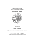
1.4 System Dissection
1.4.1 Dimensions
7
1.4.2 Front Panel
8
1.4.3 System Configuration
Item
Description
Quantity
1
TOP COVER
1
2
BASE
1
3
HDD
4
M3*0.5pitch*8L SPRING SCREW
4
5
HEXAGON SCREW
4
6
ACE-B7400
1
7
MOUNTING BRACKET
2
8
KEY LOCK
1
9
FAN
2
BRACKET
1
10 WIRE MOUNT
3
9
Chapter 2 Procedures of Assembly/Disassembly
2.1 SO-DIMM Installation
The following instructions will guide you to install SO-DIMM step-by-step.
2.1.1 Unlock key of chassis top cover.
10
2.1.2 Open top cover.
11
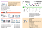
2.1.3 Install the SO-DIMM memory module into the SO-DIMM socket.
Align the memory module's cutout with the SO-DIMM slot notch.
Slide the memory module into the SO-DIMM slot.
12
2.1.4 Assemble top cover with key.
13
2.2 CF Card Installation
2.2.1 Open the top cover (the same as above steps).
2.2.2 Push the CF card into CF socket.
The direction for
installing the CF card
2.2.3 Finish the CF installation.
14
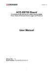
2.3 SATA HDD installation
2.3.1 Assemble SATA HDD at HDD braket with four screws.
2.3.2 Assemble to motherboard with four screws. Then install SATA cable and power
cable.
15
Board Guide
16
Chapter 1 Introduction
ACE-B7400 is an All-in-One gaming control box based on AMD most advanced Fusion platform
which integrates AMD Radeon HD 6310 graphic controller. It is designed for slot machine and
AWP machine which requires powerful 3D video performance. Besides powerful integrated
graphic controller, ACE-B7400 integrates all gaming control features.
1.1 Specifications
Items
Description
CPU Thermal Module Fan with heat sink
CPU Board
ACE-B7400
CPU
AMD FT1 processors
Single Core:T52R 1.5GHz (18W)
Dual Core:T48N 1.4GHz (18W)
System Memory
4.
5.
6.
2 x DDR3 So-DIMM slots
Maximum up to 8 Giga Bytes
1 x 1GB DDR3 SDRAM pre-installed
Storage
3.
4.
CF socket x 2
Optional 2.5” HDD bay
Extension
Not available
Front Panel
G.
H.
I.
J.
K.
L.
DVI-D
DVI-I connector
2x (RJ45 Giga LAN + 2 USB)
1 x 2 USB connector
COM1 to COM 4 (Male DB9)
Power & HDD LED
Rear Panel
F.
G.
H.
I.
J.
2x 16 pin micro fit connector for digital input
2x 20 pin micro fit connector for digital output
1x 14 pin micro fit connector for COM
1x 6 pin for audio
1x 8 pin micro fit connector for power input
Internal I/O
4. 2 x USB 2.0
5. On board intrusion switch
6. 1x intrusion input from on board 2-pin JST connector
System fan
2x temperature controllable system fan
Operation
temperature
0 to 60 Degrees Celsius
17
Expansion Module
Power requirement
Not Available
Power supply from external
1. +12V & +24V from 8-pin Micro fit connector
1.2 Package Contents
Check if the following items are included in the package.
Quick Manual
AR-B7400 board
1 x Software Utility CD
18
1.3 Block Diagram
19
Chapter 2 H/W Information
This chapter describes the installation of ACE-B7400. At first, it shows the Function
diagram and the layout of ACE-B7400. It then describes the unpacking information which
you should read carefully, as well as the jumper/switch settings for the ACE-B7400
configuration.
2.1 Mainboard illustration (Top Side)
20
LED1
Green LED: Powered On.
Orange LED: HDD Active.
PWR_BTN1
System Power Button. (note1)
DVI-D1
DVI-D Connector.
DVI-I1
DVI-I Connector.
USB1
Dual-Port USB 2.0 Connector
(USB 5, 6).
CN25
One RJ45 with Dual USB 2.0
Connector (LAN 2 & USB 3, 4).
CN26
One RJ45 with Dual USB 2.0
Connector (LAN 1 & USB 1, 2).
COM1_2
UART RS-232 Port 1, 2
(Supports 9-bits Protocol).
COM3_4
UART RS-232 Port 3, 4.
CN7
Gaming Input Isolation Connector.
(note2)
CN6
Gaming Input Isolation Connector.
(note2)
CN4
Gaming
Open-Drain
Output
Connector. (note2)
CN4
Gaming Open-Drain Output
Connector. (note2)
CN3
Selectable TTL, RS232, RS485,
cctalk Connector (UART Port 5, 6).
CN2
2.1 Channel Audio Amplifier Output
Connector.
CN1
System Power Input Connector.
U43
AMD FT1 APU. (T48N/T52R)
CF1
CF Card Slot 1.
CF2
CF Card Slot 2.
U40
Acrosser Gaming Core.
SATA1/SATA2
SATA 3.0 Connectors.
MINI-PCIE1
Mini-PCIe Slot.
CN_DIMM1/CN_DIMM2
DDR3 SODIMM Socket.
(note3)
CASESW1
Micro-switch for Chassis
Open/Close Detection.
BAT_BH1
System RTC Battery Holder.
U44
AMD Hudson-E1 Fusion Controller
Hub.
Note1: PWR_BTN can be used as a Power-Button to power-on system when FPIO1/3-4 is not
shroted. If FPIO1/3-4 is shroted by a jumper-head, system will automatically boot-up when
power applied.
Note2: Please Refer to Page8 for Rears-Panel IO Configurations.
Note3: AMD eOntario Platform supports maximum totle 8GB DDRIII Memory.
21
2.2 Locations of IO ports & Jumper Setting Definition (Top
Side)
FPIO1
System Power Button
Pin-header & Reset Jumper.
SATA_PWR1/SATA_PWR2
Two JST 2.5mm SATA Power
Connectors.
BAT_A1, BAT_B1
Lithium Battery Connector for
SRAM, AGA and secured RTC.
CN19
Clear System CMOS Jumper.
JP18
RS-485 Terminal Resistor
Selection Jumper for UART 6.
CN_USB2
JST 2.0mm USB Connector
(USB8).
JP6 ~ JP13
CN3 Output Signal Selection
Jumper.
JP17
RS-485 Terminal Resistor
Selection Jumper for UART 5.
SYSFAN2
System FAN Connector 2.
SYSFAN1
System FAN Connector 1.
AUDIO1
Internal 5.1 Channel Audio
Pin-Header.
APUFAN1
APU FAN Connector.
IButtom2
JST 2.0mm External i-Button
Connector.
JP1
cctalk Supply Power Selection
Jumper.
SPAREIO1
JST 2.0mm Gaming Spare-IO
Connector. (16-bits GPIO)
JP2/JP3
SRAM A, B Clear Jumper.
CASESW2
JST 2.0mm Chassis Open/Close
Detection Connector.
SW1
8-bit DIP-Switch Input for AGC.
JP4/JP5
Bill-enable, Coin-enable
Preset Jumper.
CN_USB1
JST 2.0mm USB Connector
(USB7).
22
Connectors and Jumpers Setting
2.1.1 FPIO1
System Power button & Reset Jumper.
JUMPER
2.1.2 CN_USB1
JST 2.0mm USB Connector (USB7).
FUNCTION
External Power Button
PIN
SIGNAL
Connection
1
VCC (+5V)
Short to Enable Auto
2
Data+
Power-on Function.
3
Data-
System Reset Button
4
GND
Connector
5
N.C
1-2
3-4
5-6
2.1.3 CN_USB1
JST 2.0mm USB Connector (USB7).
2.1.4 SYSFAN2
System FAN Connector 2.
PIN
SIGNAL
1
VCC (+5V)
PIN
SIGNAL
2
Data+
1
GND
3
Data-
2
+12V
4
GND
3
Feedback
5
N.C
2.1.5 APUFAN1
APU FAN Connector.
2.1.6 SPAREIO!
JST 2.0mm Gaming Spare-IO Connector.
PIN
SIGNAL
1
GND
2
+12V
3
Feedback
23
PIN
SIGNAL
PIN
SIGNAL
1
Bit0
2
Bit8
3
Bit1
4
Bit9
5
Bit2
6
Bit10
7
Bit3
8
Bit11
9
Bit4
10
Bit12
11
Bit5
12
Bit13
13
Bit6
14
Bit14
15
Bit7
16
Bit15
17
GND
18
+3.3V
19
GND
20
+3.3V
2.1.7 SW1
8-bits DIP-Switch Input for AGC.
2.1.8 SATA_PWR1/ SATA_PWR2
Two JST 2.5mm SATA Power Connectors.
PIN
SIGNAL
PIN
SIGNAL
1
+12V
ON
+3.3V
2
GND
OFF
GND
3
+3.3V
4
+5V
2.1.9 CN19
Clear System CMOS Jumper.
JUMPER
FUNCTION
1-2 (default)
Normal
2-3
Clear CMOS
2.1.10 JP6 ~ JP13
CN3 Output Signal TTL/RS232/RS485/cctalk
Selection Jumper.
Please See Appendix A.
2.1.12 IBUTTON2
JST 2.0mm External i-Button Connector.
PIN
SIGNAL
1
I-Button Signal
2
GND
2.1.13 JP2/JP3
SRAM A, B Clear Jumper.
24
JUMPER
FUNCTION
1-2 (default)
Normal
2-3
Clear SRAM
2.1.14 JP4/JP5
Bill-enable, Coin-enable Preset Jumper.
JUMPER
FUNCTION
1-2 (default)
Preset is “High”.
2-3
Preset is “Low”.
2.1.15 BAT_A1/BAT_B1
Lithium Battery Connector for SRAM, AGA
and secured RTC.
PIN
SIGNAL
“High” means Bill-enable, Coin-enable
1
POWER
open-drain output is short to ground.
2
GND
“Low” means Bill-enable, Coin-enable
open-drain output is open
2.1.16 JP18
2.1.17 JP17
RS-485 Terminal Resistor Selection Jumper RS-485 Terminal Resistor Selection Jumper
for UART6.
for UART5.
JUMPER
FUNCTION
JUMPER
FUNCTION
1-2 (default)
Termination
1-2 (default)
Termination
2-3
Non
2-3
Non
RS-485 terminal resistor is 120ohm.
2.1.18 AUDIO1
Internal 5.1Channel Audio Pin-Header.
PIN
SIGNAL
PIN
SIGNAL
1
Front-L
2
Front-R
3
GND
4
GND
5
Surround-L
6
Surround-R
7
IO4 GND
8
GND
9
Center
10
LFE
RS-485 terminal resistor is 120ohm.
2.1.19 JP1
ccTalk Supply Power Selection Jumper.
JUMPER
FUNCTION
1-2 (default)
+12V
2-3
+24V
+24Vpower is from CN1 external power supply.
2.1.20 CASESW2
JST 2.0mm Chassis Open/Close Detection
Connector.
PIN
SIGNAL
1
Signal
2
GND
25
Rears-Panel IO Configurations
CN1 System Power Input Connector (Micro-FIT 3.0mm 2*4 PINs)
PIN
SIGNAL
PIN
SIGNAL
1
+12V Input
5
+12V Input
2
GND
6
GND
3
GND
7
GND
4
+12V Input
8
+24V Input
Note:
1. +12V Power Input voltage tolerance is ±10%.
2. +24V Power Input is only use for cctalk Vs power supply.
CN2 2.1 Channel Audio Amplifier Output Connector (Micro-FIT 3.0mm 2*3 PINs)
PIN
SIGNAL
PIN
SIGNAL
1
Amplified Front Left +
4
Amplified Front Left -
2
Amplified Front Right +
5
Amplified Front Right -
3
Amplified LFE +
6
Amplified LFE -
Note:
1. ACE-B7400 with Audio Amplifier is D-type amp.
2. Amplified Right and Left channel support 10Watt (max) Output, Amplified LFE channel supports 20Watt (max)
Output.
CN3 Selectable TTL, RS232, RS485, cctalk Connector (Micro-FIT 3.0mm 2*7 PINs)
Pin
Signal
Signal
Pin
1
COM5 TTL/ 232 Tx/ 485 +
COM5 TTL/ 232 Rx/ 485 -
8
2
COM6 TTL/ 232 Tx/ 485 +
COM6 TTL/ 232 Rx/ 485 -
9
3
COM5 ccTalk Data
COM6 ccTalk Data
10
4
COM5 ccTalk Vcc
COM6 ccTalk Vcc
11
5
GND
GND
12
6
GND
GND
13
7
GND
GND
14
26
CN4/CN5 Gaming IO Output Connector (Micro-FIT 3.0mm 2*10 PINs)
CN4:
Pin
Signal
Pin
Signal
1
LAMP 1
11
LAMP 9
2
LAMP 2
12
LAMP 10
3
LAMP 3
13
LAMP 11
4
LAMP 4
14
LAMP 12
5
LAMP 5
15
LAMP 12
6
LAMP 6
16
Tower LAMP 1
7
LAMP 7
17
Tower LAMP 2
8
LAMP 8
18
Tower LAMP 3
9
GND
19
GND
10
GND
20
GND
Pin
Signal
Pin
Signal
1
Key-in Meter
11
Coin-Enable
2
Bill-in Meter
12
Bill-Enable
3
Coin-in Meter
13
Hopper-SSR
4
Pay-out Meter
14
GP0
5
Key-out Meter
15
GP1
6
Hand-pay Meter 1
16
GP2
7
Hand-pay Meter 2
17
GP3
8
Spare Meter
18
GP4
9
GND
19
GND
10
GND
20
GND
CN5:
Note:
1. Each LAMP output supports open-drain 500mA (max) current; each Tower LAMP output supports open-drain 1A
(max)
current.
2. Eight Meters support pulse-Generator function.
3. All output pin is open-drain circuit and operation maximum voltage cannot over +30V.
27
CN6/CN7 Gaming IO Input Connector (Micro-FIT 3.0mm 2*8 PINs)
CN6
Pin
Signal
Pin
Signal
1
Button 12
9
Touch-Cal Key-Lock
2
Button 13
10
Spare Key-Lock
3
Button 14
11
Coin-In Signal A
4
Button 15
12
Coin-In Signal B
5
Button 16
13
Bill-In
6
Dissolve Key-Lock
14
Hopper Sensor
7
OM Key-Lock
15
GP0
8
Setup Key-Lock
16
GP1
Pin
Signal
Pin
Signal
1
Door Switch 1
9
Button 4
2
Door Switch 2
10
Button 5
3
Door Switch 3
11
Button 6
4
Door Switch 4
12
Button 7
5
Door Switch 5
13
Button 8
6
Button 1
14
Button 9
7
Button 2
15
Button 10
8
Button 3
16
Button 11
CN7
Note:
1. All input pin logical high-level is +5V ~ +24V, logical low-level is 0V ~ +1.5V.
2. Coin-In Signal A, Coin-In Signal B, Bill-In, and Hopper Sensor support input counter fuction.
28
Option
IDE HDD
Auto-Detection
Choice
Enter
Description
To auto-detect the HDD's size, head…. On this channel
Auto Allows BIOS to automatically detect IDE/SATA
IDE Channel 0
Master
None
Auto
Manual
devices during POST
None Select this if no IDE/SATA devices are used and the
system will skip the automatic detection step and allow for
faster system start up.
Manual User can manually input the correct settings.
CHS
Access Mode
LBA
Large
Auto
Use this to set the access mode for the hard drive. The four
options are:
CHS/LBA/Large/Auto
Capacity
N/A
Capacity of currectly installed hard drive.
Cylinder
N/A
Number of cylinders
Head
N/A.
Number of heads
Precomp
N/A.
Write precomp
Landing Zone
N/A
Landing zone
Sector
N/A
Number of sectors
29
Chapter 3 BIOS Settings
This chapter describes the BIOS menu displays and explains how to perform common
tasks needed to get the system up and running. It also gives detailed explanation of the
elements found in each of the BIOS menus. The following topics are covered:
Main Setup
Advanced Chipset Setup
AMD Setup
SuperIO Setup
Security Setup
Boot Setup
Exit Setup
30
3.1 Main Setup
Once you enter the Phoenix BIOS™ CMOS Setup Utility, the Main Menu will appear on the
screen. Use the arrow keys to highlight the item and then use the <Pg Up> <Pg Dn> keys to
select the value you want in each item.
Note: Listed at the bottom of the menu are the control keys. If you need any help with the item
fields, you can press the <F1> key, and it will display the relevant information.
Option
Choice
System Date
N/A
System Time
N/A
Set the system time.
Processor Type
N/A
This item displays the CPU Type
Processor Speed
N/A
This item displays the CPU Speed
N/A
This item displays the memory speed
System Memory
Speed
Description
Set the system date. Note that the ‘Day’ automatically
changes when you set the date
31
L2 Cache Ram
N/A
This item displays the L2 ache memory size
Total Memory
N/A
This item displays the memory size that used.
N/A
This item displays the memory size that used On slot 0.
N/A
This item displays the memory size that used On slot 1.
Memory Channel slot
0
Memory Channel slot
1
32
3.2 Advanced Chipset Setup
Option
Quick Boot
Choice
Description
Enabled
Allows the system to skip certain tests while booting. This
Disabled
will decrease the time needed to boot the system.
Full Screen Logo
Enabled
Show
Disabled
Displays the full screen logo upon BIOS booting.
33
3.3 AMD Setup
34
Option
Choice
Description
Enabled Enables onboard controller if
Azalia Option
Enabled
audio device is detected
Disabled
Disabled
Turn off onboard controller to
allow external controller
OnChip SATA Channel
Enabled
Enabled Enables onboard SATA
35
Disabled
controller
Disabled
Turn off onboard SATA
controller
AHCI
OnChip SATA Type
N/A
Legacy IDE
AHCI ID3494
Integrated Graphics
Auto: Onboard VGA Fram Buffer
Size by the Main memory size
Force: set fixed Onboard VGA Fram
Buffer Size
Auto
Force
Auto
32M
64M
128M
UMA Fram Buffer Size
Select Onboard VGA Fram Buffer
Size
256M
384M
512M
1G
2G
36
3.4 Superio Setup
37
38
Option
Choice
Description
Disabled
3F8/IRQ4
2F8/IRQ3
Sets the base I/O port address and IRQ
3E8/IRQ6
for the onboard device
2E8/IRQ7
338/IRQ5
Serial Port 1/2/3/4/5/6
238/IRQ11
These read-only fields show the functions
CPU Temperature
of the hardware thermal sensor by CPU
N/A
thermal diode that monitors the chip
blocks to ensure a stable system.
Show
you
the
current
system
System Temperature
N/A
CPU Fan Speed
N/A
Show you the CPU Fan Speed.
SYS Fan1/2 Speed
N/A
Show you the System Fan1/2 Speed.
temperature.
39
CPU VCore
SYS Fan1/2 Mode
N/A
Show you the voltage of Vcore.
Faull: Fan Speed full on
Full Speed
By Temperature
By Temperature: Fan Speed by system
temperature
40
System Target Temp
50
N/A
60
40
3.5 Security Setup
41
Option
Choice
Supervisor Password
N/A
is
Description
The BIOS attempts to load the operating system from the
devices in the sequence selected in these items.
When a password has been enabled, you will be prompted
to enter your password every time you try to enter Setup.
This prevents unauthorized persons from changing any
part of your system configuration.
Pressing <Enter> on
this item for
Set Supervisor
confirmation:
Password
ENTER
PASSWORD:
Type the password, up to eight characters in length, and
press <Enter>. The password typed now will clear any
previous password from the CMOS memory. You will be
asked to confirm the password. Type the password again
and press <Enter>. You may also press <Esc> to abort the
selection and not enter a password.
To disable a password, just press <Enter> when you are
prompted to enter the password. A message will confirm
that the password will be disabled. Once the password is
disabled, the system will boot and you can enter Setup
freely.
TEMP Support
Current TPM State
Enabled
Disalbed
N/A
For Onboard TPM Module Function.
Show Current TPM States
No Change
Enable
Disable
Activate
Deactive
Clear
Enable and Activate
TPM Action
Disable and
Deactivate
N/A
Set Owner Install,
with state=True
Set Owner Install,
with state=False
Enable, Activate,
and Set Owner
Install with
42
state=True
Disable, Deactivate,
and Set Owner
Install, with
state=False
Clear, Enable, and
Activate
Require PP for
Provisioning
Do not require PP
for provisioning
Require PP for clear
Do not require PP
for clear
Enable, Activate,
and Clear
Enable, Activate,
Clear, Enable, and
Activate
43
3.6 Boot setup
44
3.7 Exit Setup
option
Exit Saving
Changes
Exit
Discarding
Changes
Choice
Pressing <Enter> on this
item for confirmation:
Pressing <Enter> on this
item for confirmation:
Description
Exit BIOS Setup and Save Changes BIOS Setting.
Exit BIOS Setup and Without Save Changes BIOS Setting.
45
When you press <Enter>
Load
Optimized
Defaults
Discard
Changes
Save
Changes
on this item you get a
confirmation dialog box with Press ‘Y’ to load the default values that are factory-set for
a message like this:
optimal-performance system operations.
Pressing <Enter> on this
item for confirmation:
N/A
Pressing <Enter> on this
item for confirmation:
Save Changes BIOS Setting but without exit BIOS Setup.
46
Chapter 4 Function Description
4.1 DC Power input connection
AR-B7400 needs +12V/+24V to power the board.
4.2 Digital Inputs
There are 4 clamped diode protection digital inputs on GPIO_COM1 connector. You can read
the status of any input through the software API. These digital inputs are general purpose input.
You can define their purpose for any digital input function. The detailed information please
refers to Software Programming Guide for how to use the API.
Following diagrams state how to connect the digital inputs to devices on the embedded system.
47
4.3 Digital Outputs
There are 4 clamped diode protection digital outputs on GPIO_COM1 connector. You can
control the output status of these digital outputs through the software API. The four digital
outputs are capable sink maximum 500 mA current for each channel and maximum output
voltage is 12V. The output reference voltage of device, please connect to GPIO
#VCC12V(Pin15). These digital outputs are general purpose outputs. The detailed information
please refers to Software Programming Guide for how to use the API.
Following diagrams state how to connect the digital outputs to devices on the embedded
system.
48
GPIO Pin Define:
PIN
SIGNAL
PIN
SIGNAL
1
GPO0
2
GPO1
3
GPO2
4
GPO3
5
GND
6
GND
7
GND
8
GND
9
GND
10
GND
11
GPI4
12
GPI5
13
GPI6
14
GPI7
15
VCC12A
4.4 Watchdog Timer
If you set a watchdog timer, you can use it to reset the system when system hangs up due to
hardware issue. After you set the watchdog timer, the software shall re-set the timer to re-start a
new cycle before it time-out. Please refer to Chapter 5 Software Installation and Programming
Guide for how to set the watchdog timer.
4.5 RS-232 Ports
There are three RS-232 ports on the AR-B6003. The COM1/COM3/COM4 are connected
through a male D-Sub 9-pin connector for serial
communication. The COM2 is connected through a cable.
Users need to plug into RS-232 or RS-422/485 connector.
For RS-422/485, please refer to SW2, SW4 and SW5
setting. The following diagram is their pin definition and
signal.
49
Pin number RS-232 male
1
DCD
2
TXD
3
RXD
4
DSR
5
GND
6
DTR
7
CTS
8
RTS
9
RI
CN_RS232_1: For RS-232 Function
Pin
SIGNAL
1
DSR
2
DCD
3
RTS
4
SIN
5
CTS
6
SOUT
7
RI
8
DTR
9
NC
10
GND
Pin
SIGNAL
1
NC
2
485_422_TX+
3
NC
4
485_422_TX-
5
422_RX2-
6
NC
7
422_RX2+
8
NC
9
NC
10
GND
CN_RS422_485_1: For RS-422, RS-485
50
4.6 Serial ATA (SATA)
There are 2 SATA 2.5 ports on the AR-B7400. There are also two SATA power connectors for
the SATA hard disks. The SATA power cable is an optional accessory. If you need a SATA power
connector, please contact your Acrosser sales representative for the quotation.
4.7 USB
There are 6 USB 2.0 interfaces on the AR-B7400. Four USB connectors are located on the
edge of the board. The other two USB ports are supported by two 5 pin internal connector. You
need a special cable for using these two USB ports and they are optional accessories.
51
Chapter 5 Driver And Utility Installation
5.1. Driver CD Interface Introduction
Acrosser provides the driver CD including the drivers, utilities, applications and
documents. For Windows environment, it can be guided by the setup program; for Linux
environment, the related files can be found at folder “ACEB7400\Linux”. The TPM drivers for
Linux are not included in this disc.
Once putting into optical driver, it will run automatically. The driver CD will also detect the MB
information to see if they are matched. The following error messages appear if you get an
incorrect driver CD.
It indicates that board information is not available.
It indicates that the program gets wrong board information.
52
5.1.1 Driver Page
Click the item, all the drivers will be selected.
53
Click the item, all selected items will be cancelled.
54
Click the “Install” icon to install the selected drivers.
ps: It is normal to get temporary blank screen while installing Chipset driver since VGA device
is switching resolution mode and data. It will turn back within 5~10 seconds.
55
Click the item to browse the CD contents.
56
Click the icon to close the program.
5.1.2 Utility Page
There are three utilities for ACE-B7400. AGC test utility is used to test on board gaming
function. Flash tool is used to update on board flash data. Sample code contains the
windows sample code to use Acrosser’s APIs. The detailed information about how to use
APIs please refers to Software Programming Guide.
57
Double click the “AGC test utility” to run the utility.
You have to install AGC driver in application tab first in order to run AGC test utility successfully.
Please run flash_tool.exe in command line. The tool will read the content of the assigned
file and write it to on board flash.
58
Double click on “sample code” will bring out the file explorer point to the sample code
folder.
59
5.1.3 Application Page
There is one application for Acrobat reader installing.
Double click the “Acrobat Reader 9.2” to install the application.
60
Double click the “AGC” to install the AGC driver. It will install siliently.
61
5.1.4 Document Page
This page will provide Acrosser board and system user manual. Please remember to
install the Acrobat Reader before you read the manual.
Double click the manual item to read the user manual.
Please install the Acrobat Reader when you see the message.
62
63
5.2 Windows XP 32bit Driver Installation
5.2.1 Please put the driver disk to optical driver. The program will appear
on the screen. Please click the “Select All” icon.
64
5.2.2 Click the “Install” icon to install the drivers.
65
5.2.3 Finish the driver installation. Please click “Yes” to restart the
system.
5.3 Windows 7 32/64bit Driver Installation
Please be noted. Since windows 7 64 bit edition needs certified digital signing to load hardware drivers,
in order to run our product correctly, the installation program will automatically enable test signing
feature if it runs under windows 7 64 bit environment.
66
5.3.1 Please put the driver disk to optical driver. Then click the “Run
setup.exe” to run the install program.
67
5.3.2 The program will appear on the screen. Please click the “Select All”
icon.
68
5.3.3 Click the “Install” icon to install the drivers.
69
5.3.4 Finish the driver installation. Please click “Yes” to restart the
system.
70
Chapter 6 Software Installation and
Programming Guide
6.1 Introduction
ACE-B7400 is an All-in-One gaming control box based on AMD 780E platform. It is
designed for slot machine and AWP machine which requires powerful 3D video performance.
Besides powerful integrated graphic controller, ACE-B7400 integrates all gaming control
features.
In order to ease the customer’s operation on ACE-B7400, Acrosser provides device driver,
application interface (API), and source code of demo application. The provided software is
available on both Windows and Linux. The API can be classified into two subclasses: Acrosser
Gaming Core V2 (AGC2) and Acrosser Gaming Agent V2 (AGA2). The details are described in
Chapter 2. All the provided software can be found in the bundled disc.
6.2 Application Interface
This chapter describes the details of the provided API function. The return value of the API
function is listed on Chapter 3.
6.2.1 AGC2
6.2.2 General Usage
6.2.2.1 Register AGC2 Resource
Description
This function is used to register the AGC2 related resource. AGC2 has to be registered by this
function before other functions are called.
Syntax
u32 registerAgc (void)
Argument
None.
6.2.2.2
Release AGC2 Resource
Description
This function is used to release the resource of AGC2.
Syntax
71
releaseAgc (void)
Argument
None.
6.2.2.3
Get Event Buffer
Description
Get an event from device event queue.
Syntax
getEventBuf (Event* event)
Argument
event: The memory address to put the Event structure from queue.
Event structure
u8 type: the types of event
If type is equal to 1, the event is a general purposed input event.
If type is equal to 2, the event is a timer timeout event.
If type is equal to 3, the event is a pulse generator finished event.
If type is equal to 4, the event is a counter overflow event.
If type is equal to 5, the event is a counter timeout event.
u8 channel: the channel index or timer index which occurred the event.
For a general purposed input event, channel stores the channel index.
For a timer timeout event, channel stores the timer index.
For a pulse generator finished event, channel stores the pulse generator index.
For a counter overflow event, channel stores the counter index.
For a counter timeout event, channel stores the counter index.
u32 value: the related value of event.
For a general purposed input event, value stores the channel high/low value.
For a timer timeout event, it is zero.
For a pulse generator finished event, it is zero.
For a counter overflow event, value stores the current counter value.
For a counter timeout event, value stores the current counter value.
6.2.2.4
Get Event Count
Description
72
Get how many events staying in device event queue.
Syntax
getEventCnt (u16* count)
Argument
count: The memory address to put the number of events in queue.
6.2.2.5
Clear Event Count
Description
Remove all queued events in device event queue and also reset counter to zero.
Syntax
clrEventBuf (void)
Argument
None.
6.2.2.6
Set Callback Function
Description
Set the callback function pointer.
Syntax
setCallBack (AgcCallback agcCallback)
Argument
agcCallback: The callback function pointer.
Example
void IOIST(Event event)
{
switch(event.type) {
case EVENT_CNTOF:
printf("Get counter reach target event: CNT%d value %d.\n", event.channel + 1, event.value);
break;
case EVENT_CNTTO:
printf("Get counter timeout event: CNT%d value %d.\n", event.channel + 1, event.value);
break;
case EVENT_GPI:
printf("Get input event: channel %d is %s.\n", event.channel, event.value ? "on" : "off");
break;
73
case EVENT_PG:
printf("Get pulse generator finish event: PG%d.\n", event.channel + 1);
break;
case EVENT_TIMER:
printf("Get timer finish event: Timer%d.\n", event.channel + 1);
break;
}
}
---------------------------------------------------------------------------------------------------Errbox = registerAgc( );
if(Errbox != 0)
printf(" Register Card Error\n");
setCallBack( IOIST );
6.2.3 SRAM
6.2.3.1 Set SRAM Mode
Description
This function is used to set SRAM operation mode.
Syntax
setSramMode(u8 mode)
Argument
mode: SRAM mode. 0 indicates independent mode; 1 indicates replicated mode.
6.2.3.2
Get SRAM Mode
Description
This function is used to get SRAM operation mode.
Syntax
getSramMode(u8* mode)
Argument
mode: The memory address to put the SRAM operation mode.
6.2.3.3
Read Byte from Memory
Description
This function is used to read SRAM data in byte alignment.
Syntax
74
getSramByte (u32 offset, u8* value)
Argument
offset: SRAM offset to read.
value: The memory address to put SRAM data.
6.2.3.4
Read Word from Memory
Description
This function is used to read SRAM data in word alignment.
Syntax
getSramWord (u32 offset, u16* value)
Argument
offset: SRAM offset to read (must in word alignment).
value: The memory address to put SRAM data.
6.2.3.5
Read Double Word from Memory
Description
This function is used to read SRAM data in double word alignment.
Syntax
getSramDword (u32 offset, u32* value)
Argument
offset: SRAM offset to read (must in double word alignment).
value: The memory address to put SRAM data.
6.2.3.6
Write Byte to Memory
Description
This function is used to write SRAM data in byte alignment.
Syntax
setSramByte (u32 offset, u8 value)
Argument
offset: SRAM offset to write
value: Value to write to SRAM.
6.2.3.7
Write Word to Memory
Description
This function is used to write SRAM data in word alignment.
Syntax
setSramWord (u32 offset, u16 value)
75
Argument
offset: SRAM offset to write (must in word alignment)
value: Value to write to SRAM.
6.2.3.8
Write Double Word to Memory
Description
This function is used to write SRAM data in double word alignment.
Syntax
setSramDword (u32 offset, u32 value)
Argument
offset: SRAM offset to write (must in double word alignment)
value: Value to write to SRAM.
6.2.3.9
Read Memory Block
Description
This function is used to read memory with a specified length.
Syntax
getSramBlock (u32 offset, u8* buffer, u32 size)
Argument
offset: SRAM offset to read
buffer: The start address of memory buffer to put SRAM data.
size: The memory block size (in byte) to read.
6.2.3.10 Write Memory Block
Description
This function is used to write data to memory with a specified length.
Syntax
setSramBlock (u32 offset, u8* buffer, u32 size)
Argument
offset: SRAM offset to write
buffer: The start address of data buffer to write to SRAM.
size: The memory block size (in byte) to write.
6.2.4 General Purpose Input/Output
6.2.4.1 Get Channel Status
Description
This function is used to get the status of the selected I/O channel.
76
Syntax
getChStatus (i32 ch, u32* status)
Argument
ch: Channel number.
status: The memory address to put channel status. For input channel, 0 indicates open
circuit; 1 indicates closed circuit. For output channel, 0 indicates switch off; 1 indicates
switch on.
6.2.4.2
Set Input Channel Debounce Time
Description
Set the debounce time for the selected channel (in ms).
Syntax
setDiDebounce (i32 ch, u8 time)
Argument
ch: Input channel number.
time: The de-bounce time. 0 indicates the debounce feature is disabled; others indicate
the debounce time in ms, e.g., 1 means debounce time is 1 ms.
6.2.4.3
Get Input Channel Debounce Time
Description
Get the debounce time for the selected channel (in ms).
Syntax
getDiDebounce (i32 ch, u8* time)
Argument
ch: Input channel number.
time: The memory address to put the debounce time value. 0 indicates the debounce
function is disabled; others indicate the debounce time in ms.
6.2.4.4
Set Input Channel Interrupt Enable Status
Description
Set the interrupt trigger type of the selected input channel.
Syntax
setDiIntEnable (i32 ch, IntType* type)
Argument
ch: Input channel number.
type:
77
If type is equal to NONE (0), no interrupts will happen while input status changed.
If type is equal to RISING (1), interrupts happen only when a rising edge is detected
at input channel.
If type is equal to FALLING (2), interrupts happen only when a falling edge is
detected at input channel.
If type is equal to BOTH (3), interrupts happen both on rising and falling edge.
6.2.4.5
Get Input Channel Interrupt Enable Status
Description
Get the interrupt trigger type of the selected input channel.
Syntax
getDiIntEnable (i32 ch, IntType* type)
Argument
ch: Input channel number.
type: The memory address to put the interrupt trigger type of the selected input channel.
6.2.4.6
Set Output Channel Status
Description
Set the status of the selected output channel.
Syntax
setDoStatus (i32 ch, u32 status)
Argument
ch: Output channel number.
status: The channel status. 0 indicates switch off; 1 indicates switch on.
6.2.4.7
Set Spare IO Direction
Description
Set the direction of all spare I/O channel.
Syntax
setGpioDir (u32 dir)
Argument
dir: 32 bit direction indicator. Every bit is related to one spare I/O channel, e.g., bit 0
indicated spare I/O channel 0, and so on. Set the related bit to 1 if programs output; set to
0 if programs input.
6.2.4.8
Get Spare IO Direction
Description
78
Get the direction of all spare I/O channel.
Syntax
getGpioDir (u32* dir)
Argument
dir: The memory address to put the direction indicator.
6.2.4.9
Set Spare IO Status
Description
Set the output status of the selected spare IO channel. Only the channel which direction bit is
set to 1 takes effect.
Syntax
setGpioStatus (i32 ch, u32 status)
Argument
ch: Spare I/O channel index. From GPIO0 to GPIO15.
status: 0 indicates output low; 1 indicated output high.
6.2.4.10 Get Spare IO Status
Description
Get the status of the spare IO channel.
Syntax
getGpioStatus (u32* status)
Argument
status: The memory address to put the spare IO channel status. Every bit is related to
one spare I/O channel, e.g., bit 0 indicated spare I/O channel 0, and so on. For input
channel, 0 indicates input low; 1 indicates input high. For output channel, 0 indicates
output low; 1 indicates output high.
6.2.4.11 Get Door Switch Status
Description
Get the status of the selected door switch.
Syntax
getDoorSw (i32 sw, u32* status)
Argument
sw: Door switch number. ALL indicates getting all door switches. To specify a dedicated
door switch, set value range from DOOR1 to DOOR7.
status: The memory address to put the channel status. 0 indicates output low; 1 indicates
output high. If sw equals to ALL, bit0 (the lowest significant bit) of value means the status
79
6.2.4.12 Get Button Status
Description
Get the status of the selected button.
Syntax
getBut (i32 but, u32* status)
Argument
but: Button number. ALL indicates getting all buttons. To specify a dedicated button, set
value range from BUT1 to BUT16.
status: The memory address to put the channel status. 0 indicates output low; 1 indicates
output high. If but equals to ALL, bit0 (the lowest significant bit) of value means the status
of BUT1, bit1 means the status of BUT2, and so on.
6.2.4.13 Get Key Status
Description
Get the status of the selected key.
Syntax
getKey (i32 key, u32* status)
Argument
key: Key number. ALL indicates getting all keys. To specify a dedicated key, set value
range from KEY1 to KEY5.
status: The memory address to put the channel status. 0 indicates output low; 1 indicates
output high. If key equals to ALL, bit0 (the lowest significant bit) of value means the status
of KEY1, bit1 means the status of KEY2, and so on.
6.2.4.14 Get DIP Switch Status
Description
Get the status of the selected DIP switch.
Syntax
getDipSw (i32 dip, u32* status)
Argument
dip: DIP switch number. ALL indicates getting all DIP switch. To specify a dedicated dip,
set value range from DIP1 to DIP8.
status: The memory address to put the channel status. 0 indicates output low; 1 indicates
output high. If dip equals to ALL, bit0 (the lowest significant bit) of value means the status
of DIP1, bit1 means the status of DIP2, and so on.
80
6.2.4.15 Get Lamp Status
Description
Get the status of the selected lamp.
Syntax
getLamp (i32 lamp, u32* status)
Argument
lamp: Lamp number. ALL indicates getting all lamps. To specify a dedicated lamp, set
value range from LAMP1 to LAMP16.
status: The memory address to put the channel status. 0 indicates output low; 1 indicates
output high. If lamp equals to ALL, bit0 (the lowest significant bit) of value means the
status of LAMP1, bit1 means the status of LAMP2, and so on.
6.2.4.16 Set Lamp Status
Description
Set the status of the selected lamp.
Syntax
setLamp (i32 lamp, u32 status)
Argument
lamp: Lamp number. ALL indicates getting all lamps. To specify a dedicated lamp, set
value range from LAMP1 to LAMP16.
status: The channel status. 0 indicates output low; 1 indicates output high. If lamp equals
to ALL, bit0 (the lowest significant bit) of value means the status of LAMP1, bit1 means
the status of LAMP2, and so on.
6.2.4.17 Get Coin In A Input Status
Description
Get the status of CoinIn A
Syntax
getCoinInA (u32* status)
Argument
status: The memory address to put the channel status. 0 indicates open circuit; 1
indicates closed circuit.
6.2.4.18 Get Coin In B Input Status
Description
Get the status of CoinIn B
Syntax
81
getCoinInB (u32* status)
Argument
status: The memory address to put the channel status. 0 indicates open circuit; 1
indicates closed circuit.
6.2.4.19 Get Bill In Input Status
Description
Get the status of BillIn
Syntax
getBillIn (u32* status)
Argument
status: The memory address to put the channel status. 0 indicates open circuit; 1
indicates closed circuit.
6.2.4.20 Get Hopper Sensor Input Status
Description
Get the status of Hopper Sensor.
Syntax
getHopperSensor (u32* status)
Argument
status: The memory address to put the channel status. 0 indicates open circuit; 1
indicates closed circuit.
6.2.4.21 Get Coin Enable Status
Description
Get the status of Coin Enable channel.
Syntax
getCoinEnable (u32* status)
Argument
status: The memory address to put the channel status. 0 indicates switch off; 1 indicates
switch on.
6.2.4.22 Set Coin Enable Status
Description
Set the status of Coin Enable channel.
Syntax
setCoinEnable (u32 status)
Argument
82
status: 0 indicates switch off; 1 indicates switch on.
6.2.4.23 Get Bill Enable Status
Description
Get the status of Bill Enable channel.
Syntax
getBillEnable (u32* status)
Argument
status: The memory address to put the channel status. 0 indicates switch off; 1 indicates
switch on.
6.2.4.24 Set Bill Enable Status
Description
Set the status of Bill Enable channel.
Syntax
setBillEnable (u32 status)
Argument
status: 0 indicates switch off; 1 indicates switch on.
6.2.4.25 Get Hopper SSR Status
Description
Get the status of Hopper SSR channel.
Syntax
getHopperSsr (u32* status)
Argument
status: The memory address to put the channel status. 0 indicates switch off; 1 indicates
switch on.
6.2.4.26 Set Hopper SSR Status
Description
Set the status of Hopper SSR channel.
Syntax
setHopperSsr (u32 status)
Argument
status: 0 indicates switch off; 1 indicates switch on.
6.2.4.27 Set Pulse Generator Enable Status
Description
Set the enable status of the selected pulse generator.
83
Syntax
enablePg (i32 pg, u32 enable)
Argument
pg: Pulse generator number. Range from PG1 to PG8.
enable: The enable status of the selected pulse generator. 0 indicates the output channel
works as a general-purpose output; 1 indicates the output channel works as a pulse
generator.
6.2.4.28 Set Pulse Generator Parameters
Description
Set all parameters of the selected pulse generator and immediately start it.
Syntax
setPg (i32 pg, u8 base, u8 duration, u16 cycle)
Argument
pg: Pulse generator number. Range from PG1 to PG8.
base: The pulse generator timebase of the selected output channel. 0 indicates the base
is 1 ms; 1 indicates the base is 100 ms.
duration: The time of the related pulse generator remains high in one cycle. The pulse
generator works as 50% duty cycle.
cycle: The number of the related pulse generator running cycle.
6.2.4.29 Get Pulse Generator Current Remaining Cycle
Description
Get the remaining cycle of the selected pulse generator.
Syntax
getPg (i32 pg, u16* cycle)
Argument
pg: Pulse generator number. Range from PG1 to PG8.
cycle: The memory address to put the remaining cycle of the selected pulse generator.
6.2.4.30 Stop Pulse Generator
Description
Immediately stop the selected pulse generator.
Syntax
stopPg (i32 pg, u16* cycle)
Argument
84
pg: Pulse generator number. Range from PG1 to PG8.
cycle: The memory address to put the remaining cycle of the selected pulse generator.
6.2.4.31 Set Counter Enable Status
Description
Set the enable status of the selected counter.
Syntax
enableCnt (i32 cnt, u32 enable)
Argument
cnt: Counter index. Range from CNT1 to CNT4.
enable: The enable status of the selected counter. 0 indicates the input channel works as
a general-purpose input; 1 indicates the input channel works as a counter.
6.2.4.32 Clear Counter Value
Description
Clear the selected pulse generator value to zero and feedback the current value.
Syntax
clearCnt (i32 cnt, u16* value)
Argument
cnt: Counter index. Range from CNT1 to CNT4.
value: The memory address to put the current counter value of the selected counter.
6.2.4.33 Set Counter Parameters
Description
Set all parameters of the selected counter and immediately start it.
Syntax
setCnt (i32 cnt, u8 type, u8 timeout, u16 target)
Argument
cnt: Counter index. Range from CNT1 to CNT4.
type: 0 indicates counter increases while rising edge is detected; 1 indicates counter
increases while falling edge is detected.
timeout: The time interval that counter has to wait to trigger interrupt if the input states
remains unchanged. The unit is 1ms. This interrupt is related to counter timeout event.
target: The counter will trigger an interrupt if it counts to target value. This interrupt is
related to counter overflow event. Counter value will automatically return to 0 if it counts
to target value.
85
6.2.4.34 Get Counter Current Value
Description
Get the current count value of the selected counter. The counter value remains unchanged
after this action.
Syntax
getCnt (i32 cnt, u16* value)
Argument
cnt: Counter index. Range from CNT1 to CNT4.
value: The memory address to put the current count value of the selected counter.
6.2.4.35 Setup Coin Hopper Action
Description
Specify the Counter4 parameters and set Hopper SSR to closed circuit. If the specify counter
target is reached, Hopper SSR will immediately change to open circuit. The Hopper Sensor
channel (Counter4) will set to counter mode automatically. A counter overflow event will also
log in the event queue if all actions are finished.
Syntax
setCoinHopper(u8 type, u8 timeout, u16 target)
Argument
type: 0 indicates counter increases while rising edge is detected; 1 indicates counter
increases while falling edge is detected.
timeout: The time interval that counter has to wait to trigger interrupt if the input states
remains unchanged. The unit is 1ms. This interrupt is related to counter timeout event. To
be noted, even timeout event happened, Hopper SSR will not change status.
target: The counter will trigger an interrupt if it counts to target value. This interrupt is
related to counter overflow event. Counter value will automatically return to 0 if it counts
to target value.
6.2.5 Timer
6.2.5.1 Set Timer Parameters
Description
Set all parameters of the selected timer and immediately start it.
Syntax
setTimer (i32 timer, u8 mode, u8 base, u16 value)
Argument
timer: The timer number. Range from TIMER1~TIMER4.
86
mode: The running mode of the selected timer. 0 indicates simple timer. 1 indicates cycle
timer. Cycle timer mode will immediately restart from setting value once it counts to zero.
base: The time base of the selected timer. 0 indicates the base is 1μs; 1 indicates the
base is 1ms; 2 indicates the base is 1s.
value: The countdown value of the selected timer.
6.2.5.2
Get Timer Current Remaining Count
Description
Get the remaining count of the selected timer.
Syntax
getTimer (i32 timer, u16* value)
Argument
timer: Timer number. Range from TIMER1~TIMER4.
value: The memory address to put the remaining count of the selected timer.
6.2.5.3
Stop Timer
Description
Stop the selected timer.
Syntax
stopTimer (i32 timer)
Argument
timer: Timer number. Range from TIMER1~TIMER4.
6.3 AGA2
6.3.1 General Usage
6.3.1.1 Get AGA2 Version Information
Description
This function is used to get the version information of AGA2.
Syntax
getInfo (AgaInfo* agaInfo)
Argument
agaInfo: The memory address to put AgaInfo structure.
AgaInfo structure
u8 model[8]: 8 bytes model information.
u8 majorVersion[2]: 2 byte major version of AGA2.
87
u8 minorVersion: 1 byte minor version of AGA2.
6.3.1.2
Set AGA2 Password
Description
This function is used to set the password of AGA2. The default password is “00000000” in
ASCII code.
Syntax
setPwd (u8* oldpwd, u8* newpwd)
Argument
oldpwd: The memory address to put the old 8 bytes password.
newpwd: The memory address to put the new 8 bytes password.
6.3.2 Real Time Clock
6.3.2.1 Get Real Time Clock
Description
Get the real time clock.
Syntax
getRtc (struct tm* rtc)
Argument
rtc: The memory address to put the tm structure.
6.3.2.2
Set Real Time Clock
Description
Set real time clock.
Syntax
setRtc (struct tm rtc, u8* pwd)
Argument
rtc: The tm structure to put the assigned time.
pwd: The memory address to put the 8 bytes password.
6.3.3 Event Log
6.3.3.1 Get Intrusion Event Log
Description
Get all intrusion event logs and clear them at the same time.
Syntax
getIntrlog (Intrlog* intrlog, u8* pwd)
Argument
intrlog: The memory address to put the Intrlog structure. There are eight intrusion events
88
i. The HIGH to LOW log of door switch 1.
ii. The LOW to HIGH log of door switch 1.
iii. The HIGH to LOW log of door switch 2.
iv. The LOW to HIGH log of door switch 2.
v. The HIGH to LOW log of door switch 3.
vi. The LOW to HIGH log of door switch 3.
vii. The HIGH to LOW log of door switch 4.
viii. The LOW to HIGH log of door switch 4.
ix. The HIGH to LOW log of door switch 5.
x. The LOW to HIGH log of door switch 5.
xi. The HIGH to LOW log of door switch 6.
xii. The LOW to HIGH log of door switch 6.
xiii. The HIGH to LOW log of door switch 7.
xiv. The LOW to HIGH log of door switch 7.
xv. The HIGH to LOW log of system reboot.
xvi. The LOW to HIGH log of system reboot.
pwd: The memory address to put the 8 bytes password.
Intrlog structure
struct tm timestamp: The tm structure of the intrusion event log.
u8 type: The intrusion event type. HI2LO indicates the status changed from high to low.
LO2HI indicates the status changed from low to high.
6.3.3.2
Clear Intrusion Event Log
Description
Clear all intrusion event logs.
Syntax
clrIntrlog (u8* pwd)
Argument
89
pwd: The memory address to put the 8 bytes password.
6.3.3.3
Get Intrusion Event Enable Status
Description
Get all intrusion event enable status.
Syntax
getIntrlogEnable (u8* enable)
Argument
enable: The memory address to put the intrusion event enable value. 0 indicates intrusion
event log feature is disabled; 1 indicates intrusion event log feature is enabled. Bit0 (the
lowest significant bit) of enable value indicates to door switch 1, bit1 indicates door switch
2, and so on.
6.3.3.4
Set Intrusion Event Enable Status
Description
Set all intrusion event enable status.
Syntax
setIntrlogEnable (u8 enable, u8* pwd)
Argument
enable: The intrusion event enable value. 0 indicates to disable event log feature; 1
indicates to enable intrusion event log feature. Bit0 (the lowest significant bit) of enable
value indicates to door switch 1, bit1 indicates door switch 2, and so on.
pwd: The memory address to put the 8 bytes password.
6.3.3.5
Get Battery Low Event Log
Description
Get the battery low event log.
Syntax
getBatlog (i32 id, strut tm* batlog)
Argument
id: Battery index.
batlog: The memory address to put the tm structure of the battery low event.
6.3.3.6
Clear Battery Low Event Log
Description
Clear the battery low event log.
Syntax
clrBatlog (i32 id, u8* pwd)
90
Argument
id: Battery index.
pwd: The memory address to put the 8 bytes password.
6.3.4 iButton
6.3.4.1 Reset iButton
Description
Reset the iButton.
Syntax
resetiBtn (i32 id)
Argument
id: Battery index.
6.3.4.2
Get iButton Data
Description
Get one byte data from iButton.
Syntax
getiBtn (i32 id, u8* data)
Argument
id: Battery index.
data: The memory address to put the iButton data.
6.3.4.3
Set iButton Data
Description
Set one byte data to iButton.
Syntax
setiBtn (i32 id, u8 data)
Argument
id: Battery index.
data: The 1 byte data to set.
6.3.5 EEPROM
6.3.5.1 Get Data From EEPROM
Description
Get data from EEPROM.
Syntax
getEeprom (u16 offset, u8* data, u16 size)
91
Argument
offset: The offset of EEPROM.
data: The memory address to put the data from EEPROM.
size: The retrieved data size from EEPROM.
6.3.5.2
Set Data to EEPROM
Description
Set data to EEPROM.
Syntax
setEeprom (u16 offset, u8* data, u16 size)
Argument
offset: The offset of EEPROM.
data: The memory address to put the data writing to EEPROM.
size: The writing data size to EEPROM.
6.3.6 ProtectU 2.0
6.3.6.1 Set AES Key
Description
Set AES key which encrypt / decrypt secured information while communicating with AGA.
Syntax
setAesKey(u8* key)
Argument
key: The memory address to put 16 bytes AES key.
6.3.6.2
Set ProtectU 2.0 Hash Value
Description
Set ProtectU 2.0 verified hash value.
Syntax
setHash(u8* hash)
Argument
hash: The memory address to put 64 bytes hash value.
6.3.6.3
Set ProtectU 2.0 Hash Value By Assigned File
Description
Set ProtectU 2.0 verified hash value by assigned file content. The hash value is calculated by
the assigned file on the fly. Due to the different file handle mechanism, under different
operation system will require different argument. Please see the example bellowed.
92
Syntax
Windows: setHashByFile(HANDLE fd)
Linux: setHashByFile(FILE* fp)
Argument
fd: The file handle of the assigned file.
fp: The file structure pointer of the assigned file.
Example
Windows:
u8 buffer[256];
HANDLE fd;
printf("Please input file name to calculate 512 bits hash value: ");
scanf("%s", buffer);
fd = CreateFile((char*)buffer, GENERIC_READ, 0, NULL, OPEN_EXISTING, NULL, NULL);
if(INVALID_HANDLE_VALUE == fd) {
printf("Failed to open file!\n");
return;
}
setHashByFile(fd);
Linux:
u8 buffer[256];
FILE* fp;
printf("Please input file name to calculate 512 bits hash value: ");
scanf("%s", buffer);
fp = fopen((char*)buffer, "r");
if(!fp) {
printf("Failed to open file!\n");
return;
}
setHashByFile(fp);
6.3.6.4
Get ProtectU 2.0 Operating Mode
93
Description
Get ProtectU 2.0 operating mode.
Syntax
getTrustMode(u8* mode)
Argument
mode: The memory address to put operating mode value. 0 indicates Disable, 1 indicates
Unlock Enable, 2 indicates Lock Enable.
6.3.6.5
Set ProtectU 2.0 Operating Mode
Description
Set ProtectU 2.0 operating mode.
Syntax
setTrustMode(u8 mode)
Argument
mode: The operating mode value to set. 0 indicates Disable, 1 indicates Unlock Enable, 2
indicates Lock Enable.
6.3.6.6
Get ProtectU 2.0 Verification Time
Description
Get ProtectU 2.0 verification time. ProtectU2.0 will require a successful check within
verification time. Otherwise, the system will hang within one minute.
Syntax
getTrustTime(u16* time)
Argument
time: The memory address to put verification time value. The value is unit of seconds and
at most 6000.
6.3.6.7
Set ProtectU 2.0 Verification Time
Description
Set ProtectU 2.0 verification time. ProtectU2.0 will require a successful check within
verification time. Otherwise, the system will hang within one minute.
Syntax
setTrustTime(u16 time)
Argument
time: The verification time to set. The value is unit of seconds and at most 6000.
6.3.6.8
Check ProtectU 2.0 Hash Value
Description
94
Send hash value to check.
Syntax
checkTrust(u8* hash)
Argument
hash: The memory address to put 64 bytes hash value.
6.3.6.9
Check ProtectU 2.0 Hash Value By Assigned File
Description
Send hash value to check. The hash value is calculated by an assigned file on the fly. Due to
the different file handle mechanism, under different operation system will require different
argument. Please see the example bellowed.
Syntax
Windows : checkTrustByFile(HANDLE fd)
Linux : checkTrustByFile(FILE* fp)
Argument
fd: The file handle of the assigned file.
fp: The file structure pointer of the assigned file.
Example
Windows:
u8 buffer[256];
HANDLE fd;
printf("Please input file name to calculate 512 bits hash value: ");
scanf("%s", buffer);
fd = CreateFile((char*)buffer, GENERIC_READ, 0, NULL, OPEN_EXISTING, NULL, NULL);
if(INVALID_HANDLE_VALUE == fd) {
printf("Failed to open file!\n");
return;
}
checkTrustByFile (fd);
Linux:
u8 buffer[256];
FILE* fp;
95
printf("Please input file name to calculate 512 bits hash value: ");
scanf("%s", buffer);
fp = fopen((char*)buffer, "r");
if(!fp) {
printf("Failed to open file!\n");
return;
}
checkTrustByFile (fp);
6.4 Flash
6.4.1 Erase Flash
Description
Erase the entire flash. All byte value will change to 0xFF after this action.
Syntax
eraseFlash (void)
Argument
None.
6.4.2 Write Flash
Description
Write data to flash. You can only write at most 256 bytes at one time using this function. You
have to erase flash before you can successfully write any data to flash.
Syntax
setFlash (u32 offset, u8* data, u32 size)
Argument
offset: The offset of flash.
data: The memory address to put the data writing to flash.
size: The writing data size to flash. Return failed if more than 256.
6.4.3 Read Flash
Description
Read data from flash.
Syntax
getFlash(u32 offset, u8* data, u32 size)
96
Argument
offset: The offset of flash.
data: The memory address to put the data from flash.
size: The retrieved data size from flash.
97
6.5 Return Value
This chapter describes the return value of the API functions. The return
value is formatted as the following table. If the function executes successfully,
the return value is 0.
31
24 23
API Code
16 15
AGA Error Code
6.5.1 API Code
0x01 : registerAgc
0x02 : releaseAgc
0x03 : setCallBack
0x04 : getEventBuf
0x05 : getEventCnt
0x06 : clrEventBuff
0x10 : getDiIntEnable
0x11 : setDiIntEnable
0x12 : getDiDebounce
0x13 : setDiDebounce
0x14 : getChStatus
0x15 : setDoStatus
0x16 : getDoorSw
0x17 : getBut
0x18 : getKey
0x19 : getDipSw
0x1A : getLamp
0x1B : setLamp
0x20 : getGpioDir
0x21 : setGpioDir
0x22 : getGpioStatus
0x23 : setGpioStatus
0x24 : getCoinInA
0x25 : getCoinInB
0x26 : getBillIn
0x27 : getHopperSensor
0x28 : getCoinEnable
98
General Error Code
8 7
0
Reserved
0x29 : setCoinEnable
0x2A : getBillEnable
0x2B : setBillEnable
0x2C : getHopperSsr
0x2D : getHopperSsr
0x30 : enablePg
0x31 : setPg
0x32 : getPg
0x33 : stopPg
0x50 : setTimer
0x51 : getTimer
0x52 : stopTimer
0x70 : getSramByte
0x71 : getSramWord
0x72 : getSramDword
0x73 : getSramBlock
0x74 : setSramByte
0x75 : setSramWord
0x76 : setSramDword
0x77 : setSramBlock
0x78 : setSramMode
0x79 : getSramMode
0x90 : enableCnt
0x91 : clearCnt
0x92 : setCnt
0x93 : getCnt
0x94 : setCoinHopper
0xA4 : getRtc
0xA5 : setRtc
0xA6 : getIntrlog
0xA7 : clrIntrlog
0xA8 : getIntrlogEnable
0xA9 : setIntrlogEnable
0xAA : getBatlog
0xAB : clrBatlog
0xAD : resetiBtn
0xAE : getiBtn
0xAF : setiBtn
99
0xB0 : getInfo
0xB1 : setPwd
0xB2 : getEeprom
0xB3 : setEeprom
0xC1 : setHash
0xC3 : setHashByFile
0xC4 : getTrustMode
0xC5 : setTrustMode
0xC6 : getTrustTime
0xC7 : setTrustTime
0xC8 : checkTrust
0xC9 : checkTrustByFile
0xD0 : getFlash
0xD1 : setFlash
0xD2 : eraseFlash
6.5.2 AGA Error Code
0xE0 : Handshake error
0xE2 : Hash value does not match
0xE7 : Check i2c slave address acknowledge fail
0xE8 : Check i2c word address acknowledge fail
0xE9 : Check i2c data byte acknowledge fail
0xEA : iButton device not presence
0xEB : Check password fail
0xEC : Confirm password fail
0xEE : Loops timeout fail
6.5.3 General Error Code
0x01 : Serial port device fail (open/read/write)
0x02 : AGA2 handshake fail
0x04 : Incorrect input value
0x05 : Open AGC2 device fail
0x06 : Read/write AGC2 device fail
0x07 : Create thread fail
0x08 : Access I2C bus fail
0xFF : Others unknown errors
100
Appendix
Test Tool Guide
Chapter 1
Introduction
ACE-B7400 is an All-in-One gaming control box based on AMD 780E
platform. It is designed for slot machine and AWP machine which requires
powerful 3D video performance. Besides powerful integrated graphic controller,
ACE-B7400 integrates all gaming control features.
In order to ease the customer’s operation on ACE-B7400, Acrosser
provides device driver, application interface (API), and source code of demo
application. The provided software is available on both Windows and Linux.
The API can be classified into two subclasses: Acrosser Gaming Core V2
(AGC2) and Acrosser Gaming Agent V2 (AGA2). The purpose of this
document is try to guide users to use the demo application.
101
Chapter 2
SRAM
This chapter describes about SRAM test tool.
2.1 Get SRAM mode
2.1.1 Test Purpose
To get SRAM operating mode.
2.1.2 Test Example
SRAM supports two operating mode.
To test independent mode, use 2.2 Set SRAM mode and set mode to 0.
Then use 2.6 to set offset 0x20000 under 4MB setting or 0x10000 under
2MB setting, and set data as 0x55. After then, use 2.6 to set offset 0x0 and
data as 0x0. Use 2.3 to get offset 0x0 and verify if its value is 0x0 and get
offset 0x20000 under 4MB setting or 0x10000 under 2MB setting and verify
if its value is 0x55. If so, SRAM is running in independent mode.
To test replication mode, use 2.2 Set SRAM mode and set mode to 1. Then
use 2.6 to set offset 0x20000 under 4MB setting or 0x10000 under 2MB
setting, and set data as 0x55. After then, use 2.6 to set offset 0x0 and data
as 0x0. Use 2.3 to get offset 0x0 and verify if its value is 0x0 and get offset
0x20000 under 4MB setting or 0x10000 under 2MB setting and verify if its
value is 0x0. If so, SRAM is running in replication mode.
2.1.3 Test Criteria
As stated at 2.1.2.
2.2 Set SRAM mode
2.2.1 Test Purpose
To set SRAM operation mode.
2.2.2 Test Example
Set mode = 0 as independent mode. Set mode = 1 as replication mode.
2.2.3 Test Criteria
Use 2.1 to get SRAM operation mode to verify if the same as setting mode.
2.3 Get SRAM data in byte style
2.3.1 Test Purpose
To read SRAM data with byte alignment
2.3.2 Test Example
Use 2.6 to set offset 0x0, data 0x0. And then use this function to get offset
0x0 data.
2.3.3
Test Criteria
102
If getting value is equal to 0, then test passed.
2.4 Get SRAM data in word style
2.4.1 Test Purpose
To read SRAM data with word alignment
2.4.2 Test Example
Use 2.7 to set offset 0x0, data 0x0. And then use this function to get offset
0x0 data.
2.4.3 Test Criteria
If getting value is equal to 0, then test passed.
2.5 Get SRAM data in double word style
2.5.1 Test Purpose
To read SRAM data with double word alignment
2.5.2 Test Example
Use 2.8 to set offset 0x0, data 0x0. And then use this function to get offset
0x0 data.
2.5.3 Test Criteria
If getting value is equal to 0, then test passed.
2.6 Set SRAM data in byte style
2.6.1 Test Purpose
To write SRAM data with byte alignment
2.6.2 Test Example
Refer to 2.3
2.6.3 Test Criteria
Refer to 2.3
2.7 Set SRAM data in word style
2.7.1 Test Purpose
To write SRAM data with word alignment
2.7.2 Test Example
Refer to 2.4
2.7.3 Test Criteria
Refer to 2.4
2.8 Set SRAM data in double word style
2.8.1 Test Purpose
To write SRAM data with double word alignment
2.8.2 Test Example
Refer to 2.5
2.8.3 Test Criteria
Refer to 2.5
103
2.9 Verify SRAM using block access method
2.9.1 Test Purpose
To verify SRAM access using block access API
2.9.2 Test Example
It will automatically write and read and then verify SRAM data from offset 0
to maximum size. It will run 1000 loops.
2.9.3 Test Criteria
A message such as “The 0 th loop passed!” indicates the first time test loop
success. If any error occurs while testing, a error message such as “Error
when verify SRAM data at offset” will appear and indicate failure in which
offset.
104
Chapter 3
GPIO
3.1 Get channel status
3.1.1 Test Purpose
To get digital I/O channel status.
3.1.2 Test Example
Get channel 5 status using this function.
3.1.3 Test Criteria
If on board chassis switch is pushed, you should get “Channel 5 is on”,
otherwise you should get “Channel 5 is off”. If so, the test is passed,
otherwise, it is failed.
3.2 Get door switch status
3.2.1 Test Purpose
To get door switches status.
3.2.2 Test Example
Get door switch 6 status using this function.
3.2.3 Test Criteria
If on board chassis switch is pushed, you should get “Door 6 is on”,
otherwise you should get “Door 6 is off”. If so, the test is passed, otherwise,
it is failed.
3.3 Get all door switches status
3.3.1 Test Purpose
To get all door switches status
3.3.2 Test Example
Refer to 3.2
3.3.3 Test Criteria
Refer to 3.2
3.4 Get button status
3.4.1 Test Purpose
To get button status
3.4.2 Test Example
Connect DI7 with DO5. Use 3.24 to set channel 47 as on.
3.4.3 Test Criteria
Verify if button 0 is on. If so, the test is passed, otherwise it is failed.
3.5 Get all buttons status
3.5.1 Test Purpose
To get all buttons status
3.5.2
Test Example
105
Refer to 3.4
3.5.3 Test Criteria
Refer to 3.4
3.6 Get key status
3.6.1 Test Purpose
To get key status
3.6.2 Test Example
Connect DI 23 with DO25. Use 3.24 to set channel 67 as on.
3.6.3 Test Criteria
Verify if key 0 is on. If so, the test is passed, otherwise it is failed.
3.7 Get all keys status
3.7.1 Test Purpose
To get all keys status
3.7.2 Test Example
Refer to 3.6.2
3.7.3 Test Criteria
Refer to 3.6.3
3.8 Get DIP switch status
3.8.1 Test Purpose
To get DIP switch status
3.8.2 Test Example
Move on board DIP switch 1 to on.
3.8.3 Test Criteria
Verify if DIP switch 1 is on.
3.9 Get all DIP switches status
3.9.1 Test Purpose
To get all DIP switches status
3.9.2 Test Example
Refer to 3.8.2
3.9.3 Test Criteria
Refer to 3.8.3
3.10 Get input channel debounce time
3.10.1 Test Purpose
To get input channel debounce time
3.10.2 Test Example
Use 3.11 to set channel 0 debounce time as 10. And then use this function
to verify if channel 0 debounce time is 10.
3.10.3 Test Criteria
106
If channel 0 debounce time is equal to 10, it is passed; otherwise, it is
failed.
3.11 Set input channel debounce time
3.11.1 Test Purpose
To set input channel debounce time
3.11.2 Test Example
Refer to 3.10.2
3.11.3 Test Criteria
Refer to 3.10.3
3.12 Get input channel interrupt enable value
3.12.1 Test Purpose
To get input channel interrupt enable value
3.12.2 Test Example
Use 3.13 to set channel 0 and enable value as 0. And then use this
function to verify if channel 0 enable value is disabled.
3.12.3 Test Criteria
If “The interrupt of input channel 0 is disabled.” is shown, the test is passed;
otherwise, it is failed.
3.13 Set input channel interrupt enable value
3.13.1 Test Purpose
To set input channel interrupt enable value
3.13.2 Test Example
Refer to 3.12.2
3.13.3 Test Criteria
Refer to 3.12.3
3.14 Get Coin-In signal A status
3.14.1 Test Purpose
To get Coin-In signal A status
3.14.2 Test Example
Connect DI28 with DO20. Use 3.24 to set channel 62 as on.
3.14.3 Test Criteria
If “Coin-In signal A is on” is shown, the test is passed; otherwise, it is failed.
3.15 Get Coin-In signal B status
3.15.1 Test Purpose
To get Coin-In signal B status
3.15.2 Test Example
Connect DI29 with DO21. Use 3.24 to set channel 63 as on.
3.15.3 Test Criteria
107
If “Coin-In signal B is on” is shown, the test is passed; otherwise, it is failed.
3.16 Get Bill-In status
3.16.1 Test Purpose
To get Bill-In status
3.16.2 Test Example
Connect DI30 with DO22. Use 3.24 to set channel 64 as on.
3.16.3 Test Criteria
If “Bill-In is on” is shown, the test is passed; otherwise, it is failed.
3.17 Get Hopper Sensor status
3.17.1 Test Purpose
To get Hopper Sensor status
3.17.2 Test Example
Connect DI31 with DO23. Use 3.24 to set channel 65 as on.
3.17.3 Test Criteria
If “Hopper Sensor is on” is shown, the test is passed; otherwise, it is failed.
3.18 Get Coin Enable status
3.18.1 Test Purpose
To get coin enable status
3.18.2 Test Example
Connect DI22 with DO24. Use 3.19 to set coin enable as on. Use 3.1 to get
channel 22 status.
3.18.3 Test Criteria
Use this function to get coin enable status. If “Coin Enable is on” is shown,
the test is passed; otherwise, it is failed.
3.19 Set Coin Enable status
3.19.1 Test Purpose
To set coin enable status
3.19.2 Test Example
Refer to 3.18
3.19.3 Test Criteria
If channel 22 is on, the test is passed; otherwise, it is failed.
3.20 Get Bill Enable status
3.20.1 Test Purpose
To get bill enable status
3.20.2 Test Example
Connect DI23 with DO25. Use 3.21 to set bill enable as on. Use 3.1 to get
channel 23 status.
3.20.3 Test Criteria
108
Use this function to get bill enable status. If “Bill Enable is on” is shown, the
test is passed; otherwise, it is failed.
3.21 Set Bill Enable status
3.21.1 Test Purpose
To set bill enable status
3.21.2 Test Example
Refer to 3.20
3.21.3 Test Criteria
If channel 23 is on, the test is passed; otherwise, it is failed.
3.22 Get Hopper SSR status
3.22.1 Test Purpose
To get hopper ssr status
3.22.2 Test Example
Connect DI24 with DO26. Use 3.23 to set hopper ssr as on. Use 3.1 to get
channel 24 status.
3.22.3 Test Criteria
Use this function to get hopper ssr status. If “Hopper SSR is on” is shown,
the test is passed; otherwise, it is failed.
3.23 Set Hopper SSR status
3.23.1 Test Purpose
To set hopper ssr status
3.23.2 Test Example
Refer to 3.22
3.23.3 Test Criteria
If channel 24 is on, the test is passed; otherwise, it is failed.
3.24 Set output channel status
3.24.1 Test Purpose
To set output channel status
3.24.2 Test Example
Connect DI0 with DO0. Use this function to set channel 42 as on. Use 3.1
to get channel 0 status.
3.24.3 Test Criteria
If channel 0 is on, the test is passed; otherwise, it is failed.
3.25 Get lamp status
3.25.1 Test Purpose
To get lamp status
3.25.2 Test Example
Connect DI0 with DI0. Use 3.26 to set lamp 1 as on. Use 3.1 to get channel
109
0 status.
3.25.3 Test Criteria
If “Lamp 1 is on” is shown, the test is passed; otherwise, it is failed.
3.26 Get all lamps status
3.26.1 Test Purpose
To get all lamps status
3.26.2 Test Example
Refer to 3.25.2
3.26.3 Test Criteria
Refer to 3.25.3
3.27 Set lamp status
3.27.1 Test Purpose
To get lamp status
3.27.2 Test Example
Refer to 3.25.2
3.27.3 Test Criteria
If channel 0 is on, the test is passed; otherwise, it is failed.
3.28 Set all lamps status
3.28.1 Test Purpose
To get all lamps status
3.28.2 Test Example
Refer to 3.25.2
3.28.3 Test Criteria
Refer to 3.27.3
3.29 Get GPIO port direction
3.29.1 Test Purpose
To get GPIO port direction
3.29.2 Test Example
Use 3.30 to set GPIO direction as 0xFF00. Use this function to get GPIO
port direction.
3.29.3 Test Criteria
If “GPIO port direction is 0xFF00” is shown, the test is passed; otherwise, it
is failed.
3.30 Set GPIO port direction
3.30.1 Test Purpose
To set GPIO port direction
3.30.2 Test Example
Refer to 3.29.2
110
3.30.3 Test Criteria
Refer to 3.29.3
3.31 Get GPIO port status
3.31.1 Test Purpose
To get GPIO port status
3.31.2 Test Example
Use 3.30 to set GPIO direction as 0xFFFF. Use 3.32 to set all GPIO status
as 0. Use this function to get GPIO port status.
3.31.3 Test Criteria
If “GPIO port status is 0x0000” is shown, the test is passed; otherwise, it is
failed.
3.32 Set GPIO port status
3.32.1 Test Purpose
To set GPIO port status
3.32.2 Test Example
Refer to 3.31.2
3.32.3 Test Criteria
Refer to 3.31.3
3.33 Enable counter
3.33.1 Test Purpose
To set GPI channel to function as a counter
3.33.2 Test Example
None
3.33.3 Test Criteria
None
3.34 Clear counter
3.34.1 Test Purpose
To clear counter value
3.34.2 Test Example
Connect DI28 with DO16. Set counter 1 parameters as trigger type to 0,
timeout value to 0, counter target to 100. Use 3.39 to generate 99 pulses
with 1ms high duty duration. Use this function to clear counter 1 value.
3.34.3 Test Criteria
If “Counter1 value is 99 and cleared to 0.” is shown, the test is passed;
otherwise, it is failed.
3.35 Set counter parameters
3.35.1 Test Purpose
To set counter parameters
111
3.35.2 Test Example
Connect DI28 with DO16. Set counter 1 parameters as trigger type to 0,
timeout value to 0, counter target to 100. Use 3.39 to generate 100 pulses
with 1ms high duty duration.
3.35.3 Test Criteria
If “Get counter reach target event: CNT1 value 0.” is shown, the test is
passed; otherwise, it is failed.
3.36 Get counter value
3.36.1 Test Purpose
To get counter value
3.36.2 Test Example
Connect DI28 with DO16. Set counter 1 parameters as trigger type to 0,
timeout value to 0, counter target to 100. Use 3.39 to generate 99 pulses
with 1ms high duty duration from PG1. Use this function to get counter
value.
3.36.3 Test Criteria
If counter value is equal to 99, the test is passed; otherwise, it is failed.
3.37 Set Coin Hopper Output
3.37.1 Test Purpose
To set coin hopper output. Specify the counter4 parameters and set hopper
ssr to closed circuit. If the specify counter target is reached, hopper ssr will
immediately change to open circuit. The hopper sensor channel (counter4)
will set to counter mode automatically. A counter overflow event will also
log in the event queue if all actions are finished.
3.37.2 Test Example
Connect DI31 with DO19. Set counter4 parameter as trigger type to 0,
timeout value to 0, counter target to 100. Use 3.22 to get hopper ssr status.
It should be on now. And then Use 3.39 to generate 100 pulses with 1ms
high duty duration from PG1. After PG1 is finished, use 3.22 to get hopper
ssr status. It should be off now. If so, the test is passed; otherwise, it is
failed.
3.37.3 Test Criteria
Refer to 3.37.2
3.38 Enable pulse generator
3.38.1 Test Purpose
To enable pulse generator
3.38.2 Test Example
None
112
3.38.3 Test Criteria
None
3.39 Set and start pulse generator
3.39.1 Test Purpose
To set and start a pulse generator
3.39.2 Test Example
Refer to 3.35.2
3.39.3 Test Criteria
Refer to 3.35.3
3.40 Stop pulse generator
3.40.1 Test Purpose
To stop pulse generator
3.40.2 Test Example
Use 3.39 to generate 100 pulses with 100ms high duty duration from PG1.
Before PG1 is finished, use this function to stop PG1.
3.40.3 Test Criteria
If “Pulse generator 1 remains xx cycles.” (xx can be any integer smaller
than 100) is shown, the test is passed; otherwise, it is failed.
3.41 Get pulse generator value
3.41.1 Test Purpose
To get pulse generator value
3.41.2 Test Example
Use 3.39 to generate 100 pulses with 100ms high duty duration from PG1.
Before PG1 is finished, use this function to get PG1 value.
3.41.3 Test Criteria
If “Pulse generator 1 remains xx cycles.” (xx can be any integer smaller
than 100) is shown, the test is passed; otherwise, it is failed.
113
Chapter 4
Timer
4.1 Set and start timer
4.1.1 Test Purpose
To set and start a timer
4.1.2 Test Example
Use this function to set timer 1 parameters as mode to 0, timebase to 2,
and range to 0x05.
4.1.3 Test Criteria
After 5 seconds, if “Get timer finish event: Timer1.” is shown, the test is
passed; otherwise, it is failed.
4.2 Stop timer
4.2.1 Test Purpose
To stop a timer
4.2.2 Test Example
Use 4.1 to set timer 1 parameters as mode to 0, timebase to 2, and range
to 0x10. Use this function to stop timer 1 before it timeouts.
4.2.3 Test Criteria
If nothing happened after 16 seconds, the test is passed; otherwise, it is
failed.
4.3 Get timer value
4.3.1 Test Purpose
To get a timer value
4.3.2 Test Example
Use 4.1 to set timer 1 parameters as mode to 0, timebase to 2, and range
to 0x10. Use this function to get timer 1 value.
4.3.3 Test Criteria
If “Timer 1 remains xx cycles.” is shown, the test is passed; otherwise, it is
failed.
114
Chapter 5
Flash
5.1 Get flash value
5.1.1 Test Purpose
To get flash value by byte
5.1.2 Test Example
Use flash_tool utility to write file to flash ram. Use this function to get offset
0 data.
5.1.3 Test Criteria
If getting data is equal to the first byte of written file, the test is passed;
otherwise, it is failed.
5.2 Flash r/w test
5.2.1 Test Purpose
To test flash r/w automatically
5.2.2 Test Example
This function will automatically generate data to write to flash and then
verify it one by one.
5.2.3 Test Criteria
If “R/W test passed!” is shown, the test is passed; otherwise, it is failed.
115
Chapter 6
AGA
To be noted, you have to set the correct AES key to successfully
communicate with AGA.
6.1 Get RTC
6.1.1 Test Purpose
To get secondary RTC value
6.1.2 Test Example
Use 6.2 to set system time. The default password is “00000000”.
6.1.3 Test Criteria
Use this function to get secondary RTC value, if it is equal to system time,
the test is passed; otherwise, it is failed.
6.2 Set RTC by system time
6.2.1 Test Purpose
To set secondary RTC value by system time
6.2.2 Test Example
Refer to 6.1.2
6.2.3 Test Criteria
Refer to 6.1.3
6.3 Set RTC by user setting
6.3.1 Test Purpose
To set secondary RTC value by user setting
6.3.2 Test Example
Set secondary RTC value to 2011/1/1 0:0:0, and week day is 1. And then
use 6.1 to verify it.
6.3.3 Test Criteria
If getting value is near with the setting value, the test is passed; otherwise,
it is failed.
6.4 Get AGA version information
6.4.1 Test Purpose
To get AGA version information
6.4.2 Test Example
None
6.4.3 Test Criteria
If “AGA version = v0.5” and “AGA model = 7400” are shown, the test is
passed; otherwise, it is failed.
6.5 Get Intrusion logs
6.5.1 Test Purpose
116
To get intrusion event logs
6.5.2 Test Example
The default password is “00000000”
6.5.3 Test Criteria
If a list of event logs is shown, the test is passed; otherwise, it is failed.
6.6 Clear Intrusion logs
6.6.1 Test Purpose
To clear intrusion logs
6.6.2 Test Example
The default password is “00000000”
6.6.3 Test Criteria
If “Return 00000000” is shown, the test is passed; otherwise, it is failed.
6.7 Set Intrusion log mask
6.7.1 Test Purpose
To set intrusion log mask
6.7.2 Test Example
The default password is “00000000”. Use this function to set intrusion log
mask to 0xFF. Use 6.8 to get intrusion log mask setting.
6.7.3 Test Criteria
If getting value is equal to 0xFF, the test is passed; otherwise, it is failed.
6.8 Get Intrusion log mask
6.8.1 Test Purpose
To get intrusion log mask
6.8.2 Test Example
Refer to 6.7.2
6.8.3 Test Criteria
Refer to 6.7.3
6.9 Get battery low log
6.9.1 Test Purpose
To get battery low log
6.9.2 Test Example
The default password is “00000000”
6.9.3 Test Criteria
If a battery log is shown, the test is passed; otherwise, it is failed.
6.10 Clear battery low log
6.10.1 Test Purpose
To clear battery low log
6.10.2 Test Example
117
The default password is “00000000”
6.10.3 Test Criteria
If “Return 00000000” is shown, the test is passed; otherwise, it is failed.
6.11 Get iButton ROM information
6.11.1 Test Purpose
To get iButton ROM information
6.11.2 Test Example
Use this function to get iButton1 (on board) information.
6.11.3 Test Criteria
If a list of iButton information is shown, the test is passed; otherwise, it is
failed.
6.12 Set AGA password
6.12.1 Test Purpose
To set AGA password
6.12.2 Test Example
Input old password as default password “00000000” and set new password
as “12345678”. Use new password to run 6.3.
6.12.3 Test Criteria
If RTC is changed, the test is passed; otherwise, the test is failed.
6.13 Read EEPROM
6.13.1 Test Purpose
To read a byte from EEPROM
6.13.2 Test Example
Use 6.14 to write EEPROM offset 0, value 0. And then use this function to
get EEPROM offset 0 value.
6.13.3 Test Criteria
If getting value is equal to 0, the test is passed; otherwise, it is failed.
6.14 Write EEPROM
6.14.1 Test Purpose
To write a byte to EEPROM
6.14.2 Test Example
Refer to 6.13.2
6.14.3 Test Criteria
Refer to 6.13.3
6.15 Auto test EEPROM
6.15.1 Test Purpose
To test EEPROM r/w automatically.
6.15.2 Test Example
118
None.
6.15.3 Test Criteria
If “Verify data…… passed!!” is shown, the test is passed; otherwise, it is
failed.
119
Chapter 7
Security
7.1 Set AES key
7.1.1 Test Purpose
To set AES key
7.1.2 Test Example
Set AES key as FFEEDDCCBBAA99887766554433221100
7.1.3 Test Criteria
If “Setup AES key to FFEEDDCCBBAA99887766554433221100” is shown, the test is passed;
otherwise, it is failed.
7.2 Set hash value by file
7.2.1 Test Purpose
To set hash value by assigned file
7.2.2 Test Example
Assign an existing file name.
7.2.3 Test Criteria
If “Set Hash value by file success!” is shown, the test is passed; otherwise, it is failed.
7.3 Set hash value
7.3.1 Test Purpose
To set hash value
7.3.2 Test Example
Set hash value as FFEEDDCCBBAA99887766554433221100
FFEEDDCCBBAA99887766554433221100 FFEEDDCCBBAA99887766554433221100
FFEEDDCCBBAA99887766554433221100
7.3.3 Test Criteria
If “Set hash value to FFEEDDCCBBAA99887766554433221100
FFEEDDCCBBAA99887766554433221100 FFEEDDCCBBAA99887766554433221100
FFEEDDCCBBAA99887766554433221100” is shown, the test is passed; otherwise it is failed.
7.4 Get trust mode
7.4.1 Test Purpose
To get trust mode
7.4.2 Test Example
Use 7.5 to set trust mode as 0. And then use this function to get trust mode.
7.4.3 Test Criteria
If “Trust mode is disabled!” is shown, the test is passed; otherwise, it is failed.
7.5 Set trust mode
7.5.1 Test Purpose
To set trust mode
7.5.2 Test Example
Refer to 7.4.2
7.5.3
Test Criteria
120
Refer to 7.4.3
7.6 Get trust time
7.6.1 Test Purpose
To get trust time
7.6.2 Test Example
Use 7.5 to set mode to 0. Use 7.7 to set trust time to 1000. And use this function to get trust time.
7.6.3 Test Criteria
If getting value is equal to 1000, the test is passed; otherwise, it is failed.
7.7 Set trust time
7.7.1 Test Purpose
To set trust time
7.7.2 Test Example
Refer to 7.6.2
7.7.3 Test Criteria
Refer to 7.6.3
7.8 Check trust by file
7.8.1 Test Purpose
To generate a 64 byte hash value by an assigned file on the fly and then check it with AGA.
7.8.2 Test Example
Use 7.2 to set hash value by an existing file. Use this function to check value by the same file.
7.8.3 Test Criteria
If “Return 00000000” is shown, the test is passed; otherwise, it is failed.
7.9 Check trust by hash value
7.9.1 Test Purpose
To check hash value with AGA
7.9.2 Test Example
Use 7.3 to set hash value to FFEEDDCCBBAA99887766554433221100
FFEEDDCCBBAA99887766554433221100 FFEEDDCCBBAA99887766554433221100
FFEEDDCCBBAA99887766554433221100. And the use this function to check value by the same
hash value.
7.9.3 Test Criteria
If “Return 00000000” is shown, the test is passed; otherwise, it is failed.
121