1
DIC310
User Manual
English version
Ver. 09.03
Inconsistencies
Incorrect placement of IRQ10, IRQ11, IRQ14, IRQ15 lines names next to SW2 microswitch (back side) on
PCBs with DNB: 31011220. For correct setting of these lines, please refer to Components Layout diagram in
this Manual.
17.09.03
Chapter 1
Short description
Application
DIC310 is a PC/104 successor of UNIOxx-5 series input-output modules. It is fully software and
functionally compatible with UNIOxx-5 series modules and is supplied in two configurations:
DIC31001 – 96 input-output channels
DIC31002 – 48 input-output channels
Module is designed for TTL, CMOS levels signals processing or system resources extension (for
example, additional system timers and arithmetic operations accelerators). FPGA (fieldprogrammed gate array) and ISP (In System Programmable) technology makes this module
perfect for using in wide range of applications; it can be quickly adapted for any particular task.
DIC310 contains four (DIC31001) or two (DIC31002) FPGA chips, each of them handles 24 I/O
channels. The circuits are loaded to FPGA from EEPROM after the power is switched on or after
hardware Reset. The circuit variant to be loaded, and therefore the way signals are processed is
changed by reprogramming the EEPROM in-system.
FPGA chips have high load capacity allowing connection of LEDs and Grayhill, Opto-22 optomodules to DIC310. The module has 10 shared interrupt lines (one line can be used by several
DIC310 modules), shared DMA channel, IOCHRDY signal former, and LED activity indicator.
Main applications:
Grayhill,Opto-22 opto-modules control
Discrete signals input and output
Frequency (duration) and phase measurement
Counter and timer operations
Frequency and PWM signals output
Timing charts generation without use of system resources
Codes transformation
Acceleration of logic or arithmetic operations
Page 1 of 10
Connections to the Module
Connected signals should have standard CMOS, TTL levels, except opto-modules connection.
Connection is done through J1-J4 (IDC-26) connectors with FC-26 ribbon cables.
To connect wires to terminal screws or to spring clips the following terminal boards can be used:
STB-26, LCD/DP-IFB, TBD-100 (Octagon Syst.)
TB-26 (Fastwel)
…or terminal boards with galvanic isolation:
MPB-xx (Octagon Syst.)
TBI-24LC (Fastwel)
TBI-24/0C (Fastwel)
TBI-0/24C (Fastwel)
TBI-16/8C (Fastwel)
TBI-8/16C (Fastwel)
All channels in groups of 8 can be pulled to GND or +5V levels via 10 kΩ resistors.
Chapter 2
Setup
Attention!
The module contains components sensitive to static electricity! Do not touch the components and
connector pins when not grounded properly. Do not connect or disconnect cables as well as
perform mounting or dismonting operations when the power is on.
Attention!
Before switching the power on, make sure the microswitches SW1 and SW2 as well as JP1…JP4
switches are set in correct positions.
Base Address Setting
SW1 (BA[5:0]) microswitch allows setting the module’s base address or the address segment in
I/O area where the module will be available to the system. In case of coincidence of SA[9:4]
address bits with BA[5:0] bits within read/write cycles in I/O area the module is accessed and the
Activity indicator is lit.
Base Address (Hex)
SW1-1
(BA5)
SW1-2
(BA4)
SW1-3
(BA3)
SW1-4
(BA2)
SW1-5
(BA1)
SW1-6
(BA0)
000h
0
0
0
0
0
0
010h
0
0
0
0
0
1
…
…
…
…
…
…
…
100h
0
1
0
0
0
0
110h
0
1
0
0
0
1
…
…
…
…
…
…
…
Page 2 of 10
Base Address (Hex)
SW1-1
(BA5)
SW1-2
(BA4)
SW1-3
(BA3)
SW1-4
(BA2)
SW1-5
(BA1)
SW1-6
(BA0)
150h*
0
1
0
1
0
1
…
…
…
…
…
…
…
200h
1
0
0
0
0
0
…
…
…
…
…
…
…
3E0h
1
1
1
1
1
0
3F0h
1
1
1
1
1
1
* – Factory setting
1 – SW1 slider in “ON” position
0 – SW1 slider in “OFF” position
Attention!
Wrong base address setting will lead to hardware conflicts in your system. Before switching the
module’s power on, make sure that the set base address is not used in your system.
I/O Channels Pulling
Pulling the groups of 8 channels down to GND level or up to +5V level is performed with the help of
JP1…JP4 jumpers.
Signals Pulling
Level
Channels FPGA1
Channels FPGA2
0-7
8-15
16-23
0-7
8-15
16-23
+5V *
JP1[1-2]
JP1[5-6]
JP1[9-10]
JP2[1-2]
JP2[5-6]
JP2[9-10]
GND
JP1[3-4]
JP1[7-8]
JP1[11-12]
JP2[3-4]
JP2[7-8]
JP2[11-12]
Level
Channels FPGA3
Channels FPGA4
0-7
8-15
16-23
0-7
8-15
16-23
+5V *
JP3[1-2]
JP3[5-6]
JP3[9-10]
JP4[1-2]
JP4[5-6]
JP4[9-10]
GND
JP3[3-4]
JP3[7-8]
JP3[11-12]
JP4[3-4]
JP4[7-8]
JP4[11-12]
* = Factory setting
Interrupt Line Setup
The modile can use 10 shared interrupt lines. The way the interrupts from FPGAs are combined
(“AND” or “OR”) and the number of IRQ3, 4, 5, 6, 7 lines is set by software and is considered in
Chapter 3 of this document. The method of interrupt generation depends on the circuit variant
loaded in each FPGA (see Appendices to the User Manual.).
The lines IRQ3, 5, 6, 7 are connected to PC104 connector directly, the lines IRQ4,10, 11, 12, 14,
15 are connected via SW2 microswitch.
Line
SW2-1
SW2-2
SW2-3
SW2-4
SW2-5
SW2-6
IRQ10
1
0
0
0
0
0
IRQ11
0
1
0
0
0
0
Page 3 of 10
Line
SW2-1
SW2-2
SW2-3
SW2-4
SW2-5
SW2-6
IRQ12
0
0
1
0
0
0
IRQ15
0
0
0
1
0
0
IRQ14
0
0
0
0
1
0
IRQ4*
0
0
0
0
0
1
* = Factory setting
1 – SW1 slider in “ON” position
0 – SW1 slider in “OFF” position
After power up and Reset interrupts are not used.
DMA Channel and IOCHRDY Request Line Setting
The module can use one shared direct access channel (DRQ1/DACK1) and IOCHRDY line.
The way the signals are formed depends on the circuit variant loaded to FPGA. After power up and
Reset these lines are not used.
Chapter 3
Control
The DIC310 module is controlled via I/O ports; their destination depends on the circuit variants
loaded in FPGA1...FPGA4. This Chapter describes only standard ports control independent of the
circuit variant. The rest circuit-specific ports are described in relevant Appendices to the User
Manual.
Addressing
DIC310 module uses extended addressing, i.e. decodes 16-bit ISA bus addresses (SA15…SA0).
The module is accessed if the set with SW1 microswitch base address (BA) matches SA9…SA4
bits while bits SA15…SA12 = Ah.
Ports of each FPGA chip occupy 16 bytes and have the following addresses relative to BA:
FPGA Addresses Relative to BA
FPGA1
FPGA2
FPGA3
FPGA4
BA+A000h
BA+A400h
BA+A800h
BA+AC00h
Page 4 of 10
Interrupts Programming
Shared interrupt line and the method of FPGA1… FPGA4 interrupts combination is set via the the
byte port with BA+A00Dh address (FPGA1 for all DIC310 modules).
Interrupts Register
Address
D7
D6
D5
D4
D3
D2
D1
D0
BA+A00Dh
&INT
FPG4
FPG3
FPG2
-
LN2
LN1
LN0
LN[2:0]
Interrupt line code (LN[2:0] = 3…7). Connection of interrupt line is done by writing
the IRQ3…IRQ7 line number code. For IRQ4, 10, 11, 12, 14, 15 lines the code
LN[2:0] = 4 should be written and an appropriate SW2 slider should be set.
FPG[4:2]
Interrupt connection bits for FPGA4, FPGA3, FPGA2. If FPGx bit is set, the
interrupt from the relevant FPGA chip is used in general interrupt.
&INT
Interrupt combination bit. If &INT bit is set, the general interrupt is formed using
the “AND” method, otherwise – the “OR” method.
After power up and Reset all interrupt lines are disconnected.
C code example for connection of interrupts from all FPGAs using the “AND” method to IRQ3 line:
outportb (BA+0xA00D,0xF3); // IRQ3, all interrupts combined using “AND” method
Circuit Identifier
Each FPGA of DIC310 has its own indentifier representing the code of the circuit loaded in it, e.g.
n00, c00, f00, x32 etc. The identifier can be read via the byte ports with BAx+Eh, BAx+Fh
addresses (BAx – base address of FPGAx):
Circuit Identifier
Address
D7
D6
D5
D4
BA+14
BA+15
D3
D2
D1
D0
SN3
SN2
SN1
SN0
a…z
SN7
SN6
SN5
SN4
a…z
ASCII-code of lowercase letters from “a” to “z”
SN[7:0]
Circuit number code (SN[7:0] = 0…255)
Attention!
Some circuit variants may not have an identifier. This is mentioned in corresponding Appendix.
C code example for reading the FPGA1…4 identifier of UNIO96-5 module is shown below:
printf("Read schematic codes DIC310:\n");
for(i=1,ba=BA+0xA00E;i<5;i++,ba+=0x0400){
c=inportb(ba);
if(c<’a’||c>’z’) {
printf("FPGA%d code: unknown\n");
continue;
}
printf("FPGA%d code:%1s%d\n",i,&c,inportb(ba+1));
}
Page 5 of 10
The letter in identifier designates the type of the circuit: “f” – frequency meters; “c”- counters;
“t”- timers; “g” – signal generators;“x” – custom circuit variants etc. The digits of an identifier
represent its sequence number.
DIC310 In-System Programming
In-System Programming technology allows to reprogram DIC310 without switching the power off. It
is done using the following software utilities:
isp.exe – programming with writing into EEPROM
isl.exe – programming without writing into EEPROM, i.e. temporarily, until the power is
turned off or Reset signal received.
These utilities can be used also for readin the module’s IDs (codes of cirquit variants in FPGAs).
For programming start one of the utilities using Base Address (Hex) and circuit variant codes for
each FPGA as parameters. For example, to write n00; g01; t00; f00 circuit variants in FPGAs of
UNIO96-5 module, run isp.exe as shown below:
isp 110 n00 g01 t00 f00
To temporarily write (without writing into EEPROM) n00 and n00 circuit variants to FPGAs of
UNIO48-5 module, run isl.exe as shown below:
isl 2F0 n00 n00
To read the indentifiers of DIC310, run ISP as shown below:
isp 1F0
The utilities, files with circuit variants, programming examples and descriptions can be found on
CD supplied with the module or at PROSOFT web site:
ftp://ftp.prosoft.ru/pub/Hardware/Fastwel/UNIOxx-5/Support/BIT
Attention!
The module is supplied with “g00” circuit variant excluding customized configurations.
Page 6 of 10
Chapter 4
Technical Information
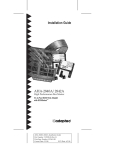
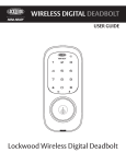
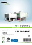
Board Layout (Top Side)
Page 7 of 10
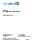
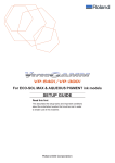
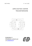
Board Layout (Bottom Side)
Technical specifications
Power voltage: +5V ±5%
Consumption current (hereinafter without channels currents) at +5V:
DIC31001 – 340 mA max
DIC31002 – 180 mA max
Operation temperature range: -40...+85°C
Storage temperature: -50...+90°C
Humidity: 95% at +25°C
Input channels levels: CMOS, TTL
Output channels levels: CMOS (at IOUT = 8 mA)
Channel output current (for opto-modules): 30 mА max
Page 8 of 10
PC/104 Connectors Pinouts
PC/104 Connector Pinout, Row A
Pin#
Name
Signal
Pin#
Name
Signal
A1
IOCHK*
-
A17
SA14
Input
A2
SD7
I/O
A18
SA13
Input
A3
SD6
I/O
A19
SA12
Input
A4
SD5
I/O
A20
SA11
Input
A5
SD4
I/O
A21
SA10
Input
A6
SD3
I/O
A22
SA9
Input
A7
SD2
I/O
A23
SA8
Input
A8
SD1
I/O
A24
SA7
Input
A9
SD0
I/O
A25
SA6
Input
A10
IOCHRDY
Output 3-d
A26
SA5
Input
A11
AEN
Input
A27
SA4
Input
A12
SA19
Input
A28
SA3
Input
A13
SA18
Input
A29
SA2
Input
A14
SA17
Input
A30
SA1
Input
A15
SA16
-
A31
SA0
Input
A16
SA15
Input
A32
GND
Input
PC/104 Connector Pinout, Row B
Pin#
Name
Signal
Pin#
Name
Signal
B1
GND
Input
B17
DACK1*
Input (OE)
B2
RESET
Input
B18
DRQ1
Output 3-d (OE)
B3
+5V
Input
B19
REFRESH*
-
B4
IRQ9
-
B20
BCLK
-
B5
-5V
-
B21
IRQ7
Output 3-d
B6
DRQ2
-
B22
IRQ6
Output 3-d
B7
-12V
-
B23
IRQ5
Output 3-d
B8
0WS*
-
B24
IRQ4
Output 3-d
B9
+12V
-
B25
IRQ3
Output 3-d
B10
AGND
-
B26
DACK2*
-
B11
SMEMW*
Input
B27
TC
-
B12
SMEMR*
Input
B28
BALE
-
B13
IOW*
Input
B29
+5V
Input
B14
IOR*
Input
B30
OSC
-
B15
DACK3*
-
B31
GND
Input
B16
DRQ3
-
B32
GND
Input
(OE) – Open-ended on delivery
Page 9 of 10
PC/104 Connector Pinout, Row D
Pin#
Name
Signal
Pin#
Name
Signal
D0
GND
Input
D10
DACK5*
-
D1
MEMCS16*
-
D11
DRQ5
-
D2
IOCS16*
-
D12
DACK6*
-
D3
IRQ10
Output 3-d
D13
DRQ6
-
D4
IRQ11
Output 3-d
D14
DACK7*
-
D5
IRQ12
Output 3-d
D15
DRQ7
-
D6
IRQ15
Output 3-d
D16
+5V
-
D7
IRQ14
Output 3-d
D17
MASTER*
-
D8
DACK0*
-
D18
GND
Input
D9
DRQ0
-
D19
GND
Input
- – Not used
Input – Input
I/O – bidirectional Input/Output
Output 3-d – Output with the third state
External Connections Table
Jx
Connector
pin
Signal name in FPGAx
Jx
Connector
pin
Signal name in FPGAx
19
IO0
3
IO13
21
IO1
5
IO14
23
IO2
7
IO15
25
IO3
13
IO16
24
IO4
16
IO17
22
IO5
15
IO18
20
IO6
17
IO19
18
IO7
14
IO20
10
IO8
11
IO21
8
IO9
12
IO22
4
IO10
9
IO23
6
IO11
2
+5V
1
IO12
26
GND
x = 1, 2, 3, 4 for DIC31001 module
x = 1, 2 for DIC31002 module
Page 10 of 10