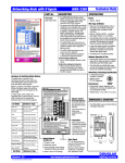
1
WRS-2224/WNX-2624
Self-Configured System
Instruction Manual
R
Contents
Contents
Introduction --------------------------------------------------------------------------- 1
Parts: WRS-2224 Programmable Relay Scanner/WNX-2624 Network Node -------- 2
Specifications & Dimensions---------------------------------------------------------- 3
LonWorks Basics --------------------------------------------------------------------- 4
Installation: Factory Pre-Assembled Systems ---------------------------------------- 5
Switch Input Types for WRS-2224 Scanner ---------------------------------------- 6
Scanner Input Hardware Type Configuration ----------------------------------------- 7
Scanner Input Switch Mode Configuration ------------------------------------------- 8
Version Numbers/Binary Code -------------------------------------------------------- 9
Programming the Relay Scanners: Normal Mode & Program Mode ---------------- 10
Output Programming: Flick Warn Option ------------------------------------------- 11
Output Programming: Time Out Option -------------------------------------------- 12
WNX-2624 Node Addresses/WRS-2224 Node Input Addresses ------------------- 13
WNS-2308 Eight-Input Network Node: Parts & Dimensions ----------------------- 14
WNS-2308 Input Hardware Type Configuration ------------------------------------ 15
WNS-2308 Input Switch Mode Configuration -------------------------------------- 16
WNS-2308 Node Addresses & Input Addresses ----------------------------------- 17
Assigning Outputs to WNS-2308 Inputs ------------------------------------------- 18
WNS-2300 Data Line Switches: Installing & Programming ------------------------ 19
Network Topology/WLP-2999 Data Signal Terminator ----------------------------- 20
WLB-2910 Data Signal Repeater ----------------------------------------------------21
Installing and Initially Configuring a New System ------------------------------------21
Replacing a Network Node ----------------------------------------------------------23
Adding a Network Node -------------------------------------------------------------24
Connections: Self-Configured Network Example ------------------------------------25
Troubleshooting ---------------------------------------------------------------- 26-27
Appendix A -Input/Output Log -------------------------------------------------- 28-29
Notes --------------------------------------------------------------------------- 30-31
Lonworks Self-Configured: Directions & Applications
lighting controls
Introduction
WRS-2224 Programmable Relay Scanner /
WNX-2624 Network Node
24V Transformer
Connections
Group Input Connections
· 5 available, each controlling one
relay group.
· Up to 6 low-voltage switching
Relay Output Connections
·
24 outputs, 12 per side.
·
The relay scanner can be
programmed with the built-in keypad
to switch a group of relay outputs
when signaled by an input from any
scanner in the network.
·
Each output group can support the
FLICK WARN switching option, while
only one group can be programmed
to support the TIME OUT option.
devices can be connected in
parallel to each input.
· Separate electrically isolated 24V
return connections provided for
groups 1, 2 & 3 and for groups
4 & 5.
Digital Link Connection
· Connect the network node to the
·
·
scanner, as shown.
LED indicator is ON when the node
is plugged into the scanner.
Power must be disconnected from
the scanner when plugging or
unplugging the node.
LookUp Buttons
· Press the NODE ID button and hold
for 3 seconds to display the node's
network address (1-24) on the
scanner.
· Press the SWITCH CODE button and
·
Service & Unconfigure Pin
· Press and hold for 3 seconds with
hold for 3 seconds to display on the
scanner (in binary code) the network
address of the selected scanner
switch input.
WINK LED, which is activated by the
network wink command, is disabled
by pressing SWITCH CODE button.
scanner in Program mode to delete
groups and return to default settings.
· Press and hold for 3 seconds with
·
scanner in Normal mode to unconfigure
the node.
Indicator LED flashes continually when
the node is unconfigured. Indicator LED
flashes on 3 seconds and off 1 second
when the node is defective.
Network Manager Select Switch
· Select one network node to be the Network
· Connect #16 AWG, unshielded
·
· Polarity insensitive.
·
Manager by setting its switch to ON position.
Indicator LED is ON when the node is
correctly set as Network Manager.
Except for the Network Manager node, this switch
must be set to OFF for all nodes in the network.
LonWorks Self-Configured: Directions & Applications
page 1
Digital Signal Connection
twisted pair data signal.
lighting controls
Parts: WRS-2224 Scanner/WNX-2624 Network Node
Relay Outputs
·
24 output terminals
(12 per side) are provided
for individual relay control.
·
Individual Output Buttons
A Douglas 2-wire switch
can be connected in parallel
to an output to permit
individual control of the
relay by that switch.
·
In NORMAL mode, use these buttons to
switch the connected relay ON or OFF.
·
In PROGRAM mode, use these buttons
to enter or remove the connected relay
to/from the group being programmed.
Relays can be combined with relays
connected to any other scanner in the
network to form a group.
Individual Output LEDs
·
In NORMAL mode, LEDs display if
the relay is ON or OFF.
·
In PROGRAM mode, LEDs display
if the relay is included in the
group that is being programmed
to the selected group input.
Master Switch 0verride Buttons
·
Mode Select
Buttons & LEDs
·
NORMAL mode.
PROGRAM mode.
OPTIONS mode:
a. FLICK WARN after OFF;
b. TIME OUT after ON.
·
·
Input Select Button
·
Use this button to select the relay
groups/switch inputs 1, 2, 3, 4 or 5.
Group Switch Inputs (5)
·
Connect Douglas 2-wire switches to
switch the group of relays ON or OFF.
·
You can connect up to 6 switches
and/or 2-wire timer outputs to the
same switch input.
Directions
·
Use these buttons to switch all of
the relays in a selected input
group ON or OFF.
Directions are printed on the
keyboard for handy user reference.
Switch Code Pin
·
Digital Link
·
Connect the node to the scanner
by plugging into socket.
·
Be sure that 24VAC is
disconnected from the scanner
before plugging or unplugging the
node.
·
·
Press to display network address (in
binary code) of selected scanner
input on scanner output LEDs 1-8.
Press and hold to reconfigure group
inputs for different switching modes.
Press to stop wink LED from
flashing.
Node ID Pin
·
w www.DouglasLightingControls.com
m
o
c
.
s
l
r
t
o
C
g
n
i
h
I
L
s
a
l
u
o
D
.
Service & Unconfigure Pin
Press to display node address (124): when pressed, the output LED
of the corresponding output # on
the scanner will turn ON.
·
Press to unconfigure the node
or to return to default settings.
Digital Signal Connection
·
Network Manager
Select Switch
·
Select one node in the network to be
the Network Manager by setting its
switch to the ON position.
·
Be sure that all other nodes in the
network have the switch set to OFF.
LonWorks Self-Configured: Directions & Applications
page 2
Connect to the network data signal
with #16AWG twisted pair,
unshielded cable.
lighting controls
Specifications & Dimensions
Specifications: WRS-2224 Scanner/WNX-2624 Node Combination
Power
Digital Link
· 24VAC / 50mA Class 2 Low Voltage devices.
· The programmable relay scanner has a digital link socket
that the network node plugs into.
· Power rating does not include power used to switch
relays.
Wire Type & Method
· The WNX-2624 Node obtains power from the WRS-2224
Scanner.
· Connect nodes together with a 2-wire cable. Use 16AWG,
twisted pair, unshielded cable, stranded or solid conductor.
· Power to a scanner must be off whenever a node is
connected or disconnected.
· Free topology network wiring is supported. Data signal can be
wired with branches and tees. Wire lengths should not exceed
the distances shown on table on page 19 of this manual.
Scanner Inputs
· Longer data signal lengths are possible if devices are
connected in a serial bus or if a repeater is used.
· There are 5 master switch inputs per scanner that are
compatible with all models of Douglas relay switches.
· Connections are not polarity sensitive.
· A maximum of 6 switches can be connected in parallel to
the same master switch input.
Self-Configured Network
· Maximum wire length for a master switch is 2000'.
Scanner Outputs
· Up to 24 nodes (WNX-2624 or WNS-2308) can exist in a
self-configured network. (Maximum number of 2308
nodes in a self-configured network is 8.)
· 24 Douglas relay outputs per scanner.
· Networking technology specification is LonWorks,
LonMark Certified (V3.1).
· Outputs can be triggered by a switch input from any
scanner in the network or from a switch input from any
other Douglas device in the network.
· Network signal is FTT-10 Transceiver.
· Outputs fire in sequence (<4 seconds) to prevent
overloads in the line and low voltage circuits.
Environment
· Indoors, stationary, non-vibrating, non-corrosive
atmosphere and non-condensing humidity.
· Connect a maximum of 4 relays to each output. Maximum
wire length per output is 500' (150m).
· Relay outputs are isolated from each other. The pulse of a
local switch connected to a relay on an output will not
pass through the scanner to a relay connected to another
output.
· Ambient operating temperature:
0O F to +1200 F (-15O to +50O C).
Dimensions & Mounting
3
1
15
13
4
2
16
14
6
18
8
20
10
22
12
24
5
17
7
Programming
·
· Use the membrane keypad built into the face of each
programmable relay scanner to assign groups of its relay
outputs to master switch inputs from any scanners or
other Douglas devices in the network.
·
· Program settings (relay groups) are not lost in the event
of a power outage.
Mount to 35mm DIN rail
6.5"
installed in relay panels.
(165 mm)
Caution: be sure to
disconnect 24VAC from
relay scanner before
plugging/unplugging node.
21
11
23
2.5"
(64 mm)
· Programming directions are printed on the front cover of
each scanner for handy reference.
LonWorks Self-Configured: Directions & Applications
19
9
page 3
4.0"
(103 mm)
1.75"
(45 mm)
Plan View
Side View
lighting controls
LonWorks Basics
LONWORKS
LONWORKS refers to a technology platform for components
used in control networks.
CONFIGURATION (continued)
In a Douglas self-configured network up to eight WNS-2308 EightInput Nodes can be used in lieu of a WNX-2624 Network Node/WRS2224 Scanner combination, as long as the total of Network Nodes
and 8-Input Nodes does not exceed 24. By default, the Network
Manager will assign Node ID#'s of 8 down to , in decreasing
sequence, to any 8-Input Nodes that are in the Network.
The LonWorks platform has a comprehensive set of standards
to which all LonWorks components must adhere. A component,
to be certified as LonWorks, must meet the functional standards
specified for its device type. The advantage to this is interoperability.
That is, in a LonWorks network, a device from any manufacturer
can be used for performing the function specified for that particular
device type.
The Network Manager will assign Input ID#'s in sequence with Input 1
of the scanner connected to the Node (or input A on a WNS-2308)
assigned the ID# of (Node ID#) x 8. Thus, Input 1 of Node #23
would be assigned Input ID #184 (23 x 8) with Input 2 assigned ID#
185, Input 3 assigned ID# 186, and so on.
LonWorks devices, in most cases, contain a chip called a Neuron.
The neuron has imbedded software that directs the device in
performing its networking functions. How a LonWorks device
works is that it 'listens' for messages from other LonWorks
devices on the network. When it 'hears' a type of message that
it is programmed to respond to, it sends a specific type of message
in response.
CONFIGURATION
A LonWorks network consists of devices that are configured to
receive/send signals to/from other devices in the network.
Configuring requires each devices to have an ID. Also, each device
must recognize the IDs of all other devices on the network so that it
can send/receive messages to/from the appropriate ones. Each
device is configured to respond in a specific manner to any message
it is able to receive.
w w .D u
l
g
o
In most LonWorks control networks, device configuration is
performed on an external PC. The Douglas Self-Configured
Lonworks network is unique, however, in that it performs its own
configuration without the need of any external computer or control
system. It accomplishes this with the neuron built into the WNX2624 Network Node.
l
r
t
n
o
.o
s
m
c
w w .Du
lo
g
s LIg
a
h tin
C
g
l
o
r
t
n
.
sc
m
o
w w .D o
l
g
u
s LIg
a
h tin
C
g
l
r
t
n
o
.o
s
mc
Self-Configured Network Example
AN EXAMPLE
Take the example of self-configured Douglas Lonworks Network,
as shown above. It consists of three panels, each containing the
WRS-2224 Programmable Relay Scanner/WNX-2624 Node. They
are networked with a data signal that is connected to the FTT-10
transceiver of each Node.
Before a Douglas Self-Configured network is initially powered up,
one of its WNX-2624 Network Nodes is selected (by manually
setting its Net Manager switch to the ON position) to be the
'Network Manager'. Upon power up, that Network Manager node will
assign itself the Network Manager Node ID number. Then, it will
search the network for other nodes and assign them all Node ID
numbers. It will also assign Input ID numbers to each group input on
each node.
The first Node is assigned as Network Manager (its Net Manager
switch is set to the ON position). Upon power up, it assigns itself
Node ID #24 and assigns the other nodes Node IDs #23 and
#22. It also assigns Input ID #'s to all the scanner Group Inputs.
Switch inputs are designated by the operator, using the
programmable relay scanners in the network, to control certain relay
outputs. The Network Manager will bind, or assign, those relay
output devices to those particular switch inputs.
A switch is connected to the first group input in Node #23 and,
using the programmable relay scanners, is assigned to a group of
three relays. Two of the relays are connected to outputs on the
scanner connected to Node #23 and one is connected to an
output on the scanner connected to Node #22.
What results is that the Network Manager will know which Node (by
its Node ID number) has which switch inputs (by their input ID
numbers) and which output relays (by the binding) each of those
switch inputs will control. Therefore, when the system is operating
and a switch input is triggered, the network will recognize where it
is, will recognize which output relays it is to trigger, and will generate
a signal to trigger those output relays.
The Network Manager Node recognizes this and assigns Input ID
#184 to the switch and binds the three relays to Input #184.
Whenever the switch is activated, it transmits a message that it,
as Input #184, is ON. In response, the network transmits a
message to the three relays, as the devices bound to Input #184,
to trigger.
A Douglas self-configured network can have a maximum of 24
Network Nodes, each with its own Node ID. By default, the Network
Manager Node will assign itself the Node ID# of 24 and will assign the
other Network Nodes sequentially decreasing ID#'s (23, 22, 21, etc.).
LonWorks Self-Configured: Directions & Applications
s LIg
a
h tin
C
g
page 4
lighting controls
Installation: Factory-Assembled Systems
INSTALLATION INSTRUCTIONS (Pre-Assembled Systems)
In most cases, a Douglas Self-Configured LonWorks system is
assembled panel-by-panel and initially configured at the factory.
For each panel in a pre-assembled and pre-configured system, it is
necessary to install the panel, check the basic network settings,
connect the switch inputs to the appropriate group inputs and
connect the outputs to the appropriate relays.
After this is done for all the panels in the network, the panels are
interconnected with the data signal following the one-line diagram
supplied with the system. If LonWorks Data Line switches are used,
they also connect to the data signal. If not previously done at the
factory, outputs can be assigned to the group inputs of each relay
scanner once the panels are interconnected.
1. Install the pre-assembled relay panels. Be sure that the panels are
located closely enough together so that the network line length
required to interconnect them does not exceed the specification
called out in the One-Line Diagram page of the drawings supplied
with the system.
2. Make sure the network manager node (the WNX-2624 Node
assigned "Unit ID 24" in the Interface List By Panel page of the
drawings supplied with the system) has its Net Manager Select
switch set to ON. Also make sure that the Net Manager Select
switch on all the other WNX-2624 Nodes is set to OFF.
3. In each panel, connect the lighting loads to the output relays of
the scanner. You should make note of which load is connected
to each relay in the relay schedule for each panel.
4. In each panel, connect the group switching devices (switch or
timer) to the scanner group inputs. If you are connecting 24V
switching devices other than a default Douglas switch or time
clock, you will have to first configure their inputs. Use the
keyboard on the scanner, as detailed in the 'Scanner Input
Configuration' section on page 7 of this manual.
5. A maximum of 6 switching devices can be connected in parallel
to the same master input, with a maximum wire length of
2000'/600m if using 18 AWG wire. Refer to 'Switch Input
Hardware Types' on page 6 of this manual for more information
on input switching devices.
8. Determine which output relays are to be switched together as groups.
Different output relays from any scanners in the network can be
grouped together to be switched by the same group input. An output
relay can also be in more than one group.
9. Use the keypad on each scanner to assign the output relays to each
group input:
a) Go to the scanner with the group input to be programmed and select
that input by toggling the scanner's INPUT SELECT BUTTON.
b) Press the scanner's PROGRAM MODE BUTTON. This places the entire
network in Program mode. The Output LED for any output, on any
scanner, that is controlled by the input will be lit.
c) Add or remove an output relay on any scanner from the input by toggling
its OUTPUT BUTTON.
d) Press the NORMAL MODE BUTTON on the input's scanner to exit the
network from Program mode.
e) Repeat steps (a-d) for other inputs.
For more details on the procedure for programming outputs to inputs,
see pages 10-12 of this manual.
NOTE: If the group input is from a WNS-2313 Data Line Switch
Module, the procedure is slightly different for assigning outputs. See
page 19 of this manual for details.
10.To assign scanner outputs to a group inut on a WNS-2308 Network
Node, follow the procedure on page 18 of this manual.
6. Interconnect the WNX-2624 Network Nodes with the data signal
wire (#16AWG, twisted pair unshielded). Be sure to connect
them in the exact order shown in the One-Line Diagram in the
drawings supplied with the system.
7. Power the system up. LEDs will flash briefly on the scanners
and Nodes as the Network Manager performs the network
startup routine. Make sure that the Net Manager LED is ON for
the Network Manager node and OFF for all the other nodes. Also
make sure that the Digital Link LED is ON on each scanner. If
not, check the connnections and the Net Manager Switch
settings.
LonWorks Self-Configured: Directions & Applications
page 5
lighting controls
Switch Input Types for WRS-2224 Relay Scanner
Switch Input Hardware Types: WRS-2224 Programmable Relay Scanner
Different types of switches can be used as inputs on the
WRS-2224 Programmable Relay Scanner.
The default switch type is the Douglas WR-8501
(momentary contact with diodes). Most models of
Douglas 2-wire switches are compatible with the default
settings of the scanner. If you are using a different
switch type, you must configure the input. If you are
using contact type switches without diodes, there will be
some restrictions in signal transmission.
SWITCH INPUTS
Switching with Momentary
Contacts that use Diodes
· ON & OFF switching with contacts from another
device or system is best accomplished with
momentary type contacts that have a diode
connected in series (one contact & diode for ON
and another for OFF).
· Momentary contacts that utilize diodes have 2
advantages:
1. It is possible to have repeat ON or OFF
commands. For example, during the night, an
OFF signal could be issued every hour to
ensure lights are swept OFF.
2. Douglas relay switches can be connected in
parallel for convenient override.
· Momentary contacts with diodes mimic the
Douglas relay switch. Thus, the default input
configuration of the WRS-2224 scanner is for
the Douglas WR-8501 relay switch.
Douglas Relay Switches
1
2
3
4
5
6
7
8
9
10
11
12
1
13
2
14
4
16
3
15
5
17
6
18
8
20
10
22
7
19
9
21
11
23
12
24
· The inputs of the WRS-2224 scanner
are compatible with all models of
Douglas relay switches. However, If you
are connecting a switch type other than
default, you must re-configure the input
before connecting the switch. Follow
the procedure described in 'Scanner
Input Configuration' on page 7 of this
manual.
13
14
15
16
17
18
19
20
21
22
23
24
W
B
WRS-2224
Relay
1
Scanner SwitchB23
Inputs
4
5
B
B Tr
W
Momentary ON Contact
ON
Diode
OFF Contact
OFF
Diode
· Inputs for the WRS-2224 can also be configured to
accept 24V signals that have no diode connected.
The signal can be momentary or maintained.
· When using the 24V contact control, be aware
there are some restrictions. An input can be
configured to switch relays ON when 24V is applied
and OFF when it is removed. However, when this
is the case it is not possible to send repeat OFF
signals without an intervening ON signal. You can
also configure the input so that only OFF signals
are sent if a repeat signal is desired, although in
this case there would be no ON signal. Should
repeat OFF as well as ON signals be needed, then
two 24V contacts would be needed with two
inputs, one for the OFF signal and one for the ON.
Refer to 'Scanner Input Configuration' on page 7 of
this manual for all the settings available for 24V
contact control.
1
13
2
14
4
16
6
18
3
15
5
17
7
19
8
20
10
22
12
24
9
21
11
23
13
14
15
16
17
18
19
20
21
22
23
24
W
B
WRS-2224
Relay
1
Scanner Switch B23
Inputs 4
5
B
B Tr
W
WR-8001 Rocker Switch
Red
WR-8501 Pushbutton
Switch with
ON & OFF LEDs
Red
Master Sw Override
Red
Switching with 24V
Momentary or Maintained
Contacts (no Diodes)
· When a Douglas switch is connected to
the scanner, the switch LEDs will show
the state of the relay group. If any of
the relays in the group are ON, the
group is defined as being ON and the
red LED will be lit. Only when all of the
relays in the group are OFF will the
group be defined as being OFF and the
green LED be lit.
1
2
3
4
5
6
7
8
9
10
11
12
Douglas switch OK with
momentary contacts.
NOT OK with maintained
contacts.
(OR)
ON Diode
Coil
OFF Diode
COM
LonWorks Self-Configured: Directions & Applications
Red
Maximum:
6 switches
WTP-4408
Douglas Timer Automation
Maintained Form C
Contact Set
NO NC
· Take care when using Douglas WR8501 switches. The WR-8501 push
button switch will always send a signal
that is opposite to its displayed state.
If repeat ON or OFF control is desired,
use the WR-8001 rocker switch which
is able to select an ON or OFF signal.
page 6
· The inputs of the WRS-2224 scanner
are compatible with Douglas timers,
such as the WTP-4408. When
connecting a Douglas timer to the WRS2224 scanner, the input must be
configured for a Douglas relay switch
(default).
· The inputs are also compatible, using
default configuration, with Douglas
sensors such as the WRM-5104
Occupancy Sensor or WPC-5621
Daylight Sensor.
Time Clock
A
B
1
Esc
C
D
2
3
4
5
2
3
6
4
7
5
8
6
9
7 08
9
1
S e n s o r
S e n s o r
Clr
W
1
2
3
4
5
6
0
7
W
8
B
lighting controls
Scanner Input Configuration: Hardware Types
Output Buttons
#13-#23
Scanner Input Configuration, Hardware Types
This configuration determines which type(s) of switching hardware can be
connected to a group switch input of a WRS-2224 Relay Scanner.
The default switch type for all inputs is the Douglas WR-8501 with LED
Indicators. This input configuration is compatible with all models of Douglas
relay switches, relay time clocks, occupancy sensors and photo sensors and
no reconfiguration is necessary for those devices.
However, if you will be connecting any different switch type(s) to an input of a Flick
scanner in the network, follow this procedure.
Warn
NOTE: Scanner Input Hardware Type Configuration, which is internal to each LED
scanner, is independent of Network Configuration, which is proprietary to the
WNX-2624 Network Nodes.
Normal Mode
Select Button
To Configure a Scanner's Inputs for Hardware Types:
Options Mode
Select Button
Input
Select
Button
1. Make sure NORMAL MODE is selected. Its indicator light should be ON.
2. Use the INPUT SELECT BUTTON to scroll to and select the group input #1-5 you wish to
configure (when its indicator LED is ON).
3. Press and hold the OPTIONS MODE select button. The FLICK WARN LED will begin flashing.
Input
LEDs
4. One of the LEDs #13-23 will display, showing the current configuration selected for the
input. Refer to the table below for a list of all available configurations. The factory default is
#21, the Douglas WR-8501 LED indicator rectified AC pulse switch.
5. Depress the appropriate OUTPUT SELECT BUTTON (#13-23) to select the desired
configuration for the input.
You have 10 seconds to do this. After 10 seconds, the FLICK WARN LED stops flashing and
the scanner reverts to NORMAL mode.
6. Repeat steps 2-5 to configure other group inputs on the scanner.
Output Button
Pressed
Switch Type Configured for
13
AC
Momentary
Contact.
14
15
(13) - ON when switched
(14) - OFF when switched
(15) - OPEN=OFF / CLOSED=ON
16
17
Action
(16) - OPEN=ON / CLOSED=OFF
AC
Maintained
Contact.
Coil
(17) - OPEN=no action / CLOSED=ON
18
(18) - OPEN=no action / CLOSED=OFF
19
(19) - OPEN=ON / CLOSED=no action
20
(20) - OPEN=OFF / CLOSED=no action
21 (Default)
LEDs
22
23
Rectified AC Pulse.
Current for Indicator LEDs.
NOTE: Non-LED switches are also
compatible with this configuration.
Rectified AC Pulse.
No current for Indicator LEDs.
NOTE: LED switches will not function
properly with this configuration.
LonWorks Self-Configured: Directions & Applications page 7
(21) - Positive=OFF / Negative=ON
(22) - Positive=ON / Negative=OFF
(23) - Positive=OFF / Negative=ON
lighting controls
Scanner Input Configuration: Output Function
Output LEDs
#13-#24
Scanner Input Configuration, Output Function
This configuration specifies how the outputs will be switched when a
group switch input of a WRS-2224 Relay Scanner is activated.
The default switch mode for all inputs is ON/OFF. In most cases you
would use this input setting and program the outputs as explained on
pages 10-12 of this manual.
If you wish to configure a different type of switching response for an
input to a WRS-2224 scanner, however, follow this procedure.
NOTE: Scanner Input Configuration, which is internal to each scanner,
is independent of Network Configuration, which is proprietary to the
WNX-2624 Network Nodes.
To Configure a Scanner's Inputs for Output Function:
1. Make sure NORMAL MODE is selected. Its indicator light should be ON.
2. Use the INPUT SELECT BUTTON to scroll to and select the group input #1-5 you wish to
configure (when its indicator LED is ON).
Normal
Mode
Select
Button
Program
Mode
Select
Button
Input
Select
Button
3. Press and hold the SWITCH CODE PIN on the attached WNX-2624 network node for 3
seconds. The LED adjoining the PROGRAM MODE SELECT BUTTON on the scanner will
begin flashing.
Input
LEDs
4. One of the LEDs #13-24 will display, indicating the current output function configured for the
input. Refer to the table below for a list of all available configurations. The factory default is
#23, where relays turn ON or OFF in response to a pulse signal.
Switch
Code
Pin
5. Depress the appropriate OUTPUT SELECT BUTTON (#13-24) to select the desired
configuration for the input.
You have 10 seconds to do this. After 10 seconds, the PROGRAM MODE LED stops flashing
and the scanner will revert to NORMAL mode.
6. Repeat steps 2-5 to configure other group inputs on the scanner. When finished, press the
SWITCH CODE PIN on the network node to exit.
Output Button
Pressed
Output Relay Action
Switching Mode
13
All relays turned OFF when a group switch is activated.
(13) - OFF only
14
All relays turned ON when a group switch is activated.
(14) - ON only
(16) - TimeOut
17
FLICK WARN: lights flash to warn occupants that they will be turning OFF and will turn
OFF five minutes thereafter unless occupant flips switch. (refer to page 11).
TIME OUT: timer starts when group switch activated and all lights switch OFF when
timer expires after 2 hours (refer to page 12).
TIME OUT with FLICK WARN: Time out with flick warn to provide occupants warning
before lights switched OFF when timer expires.
18
All relays turned OFF 15 minutes after a group switch is activated.
(18) - Delay OFF
19
All relays turned OFF 15 minutes after a group switch is activated with FLICK WARN
(19) - Delay OFF & Flick
20
All relays turned ON 15 minutes after a group switch is activated.
(20) - Delay ON
15
16
21
22
(Default) 23
24
(15) - Flick
(17) - TimeOut & Flick
Relays within the group that were OFF are turned ON when input switch activated,
then only those relays are turned OFF when input switch activated again.
Relays within the group switch OFF, then ON again after 6 seconds (6-second delay is
called the 'wink' in this case). Intended for use with sentry switches.
(22) -Wink (Sentry)
Relays turn ON or OFF in response to appropriate pulse signal.
(23) - Regular ON/OFF (default)
Relays change state to ON or OFF when this group switch activated while retaining
their programming (e.g., TIME OUT ) from another group input.
(24) - Redo ON/OFF
LonWorks Self-Configured: Directions & Applications page 8
(21) - Clean ON
lighting controls
Version Numbers/Binary Code
VERSION NUMBER DISPLAY
When a Programmable Relay Scanner is the in NORMAL
mode and you press its NORMAL Mode Select Button,
some of its Output LEDs, as well as the Normal Mode
Select Button's indicator LED, will flash for 10 seconds.
The combination of flashing Output LEDs 1-8 (left output
terminal) indicates the version number -in binary code- of
that Programmable Relay Scanner.
The combination of flashing Output LEDs 13-20 (right
output terminal) indicates the version number -in binary
code- of the WNX-2624 Network Node attached to the
Scanner.
Binary Code
BINARY CODE is a method of
expressing all whole numbers
as some combination of
powers of the number 2.
Output LEDs
A power of 2 is the number of
times 2 is multiplied by itself,
where 2O =1, 21=2, 22=4,
23=8, etc.
Normal Mode
Select Button
In binary code, the number one
would be 2O, the number two
would be 21, the number three
would be 20+21 (1+2), and the
number four would be 22.
Similarly, you can express all
whole numbers as either a
power of 2 or as a sum of two
or more powers of 2.
Equivalent
Numbers Flashing LEDs
0 = none
(none flashing)
1 = 20
first
2 = 21
second
3 = 20+21
first & second
4 = 22
third
5 = 20+22
first & third
6 = 21+22
second & third
7 = 20+21+22 first, second & third
8 = 23
fourth
Scanner Version # LEDs Flashing
3.0
3.1
3.2
3.3
3.4
#5, #6
#1, #5, #6
#2, #5, #6
#1, #2, #5, #6
#3, #5, #6
Node Version # LEDs Flashing
4.0
4.1
4.2
4.3
4.4
#19
#13, #19
#14, #19
#13, #14, #19
#15, #19
1. Any flashing output LEDs 1-8 indicate the version number of the
WRS-2224 Relay Scanner, with any flashing LEDs 1-4 indicating
the integer after the decimal point and any flashing LEDs 5-8
indicating the integer before the decimal point.
2. The combination of flashing numbers #1-4 and #5-8 denote the
integers in binary code (see the insert at the upper right).
3. In like manner, any flashing output LEDs 13-20 indicate the
version number of the WNX-2624 Network Node. The combination
of flashing LEDs 13-16 indicates the integer after the decimal
point and the combination of flashing LEDs 17-20 indicates the
integer before the decimal point.
4. See the table at the right for examples of the flashing LED
combinations for some version numbers that may currently be in use.
LonWorks Self-Configured: Directions & Applications
page 9
lighting controls
Programming the Relay Scanners: Normal Mode & Program Mode
NORMAL MODE
Allows the connected relays to be switched with the scanner. A scanner
should be in this mode unless the scanner network is being programmed.
Output
Buttons
Output LEDs
To Use Normal Mode:
1. The WRS-2224 Scanner will usually be in NORMAL mode (the LED above
NORMAL MODE SELECT BUTTON is lit). If left in PROGRAM mode, it will
revert to NORMAL mode after 2 minutes.
2. In NORMAL mode, an OUTPUT LED will be ON if the connected relay is ON.
Program Mode
Select Button
Normal Mode
Select Button
3. A flashing OUTPUT LED in NORMAL mode indicates a defective relay or two
relays connected to the same terminal with one relay ON and the other OFF.
4. If any relay scanner in the network is in PROGRAM Mode (the LED above its
PROGRAM MODE SELECT BUTTON is lit), all the scanners in the network
will be in group programming mode. They will still respond to local switching
but not to network switching. To return all scanners to NORMAL mode,
press the PROGRAM MODE SELECT BUTTON of the scanner that is in
PROGRAM Mode.
PROGRAM MODE
Allows output relays on different scanners in the network to be grouped,
with each group controlled by a scanner's switch input.
To Use Program Mode:
Output
Buttons
1. Go to the relay scanner whose input will be controlling the output group.
Output LEDs
2. Make sure NORMAL MODE is selected. Its indicator LED should be ON.
3. Use the INPUT SELECT button to scroll to and select the desired input #1-5 (when
its indicator LED is ON).
Program Mode
Select Button
4. Press the PROGRAM MODE select button. Its LED will begin flashing.
The OUTPUT LEDs of the output relays that are controlled by the selected
input will be ON at their respective scanners.
ON Override
Select Button
5. Add or remove output relays from the selected input by pressing the OUTPUT
BUTTON of the desired relay on the scanner the relay is connected to.
OFF Override
Select Button
Input
Select Button
6. When you have selected all the relays for the group, press the NORMAL MODE
BUTTON on the input's scanner to return all network scanners to NORMAL mode.
7. Repeat steps #1 - 6 to program other inputs with a relay group. NOTE: An
output relay can be in more than one group.
Input Terminals
Input LEDs
8. When you are programming a relay group, you can include or exclude all the output
relays in a scanner by pressing the ON OVERRIDE or OFF OVERRIDE button,
respectively.
9. When you are in NORMAL mode, you can turn all the relays assigned to an input
ON or OFF by selecting that input with the INPUT SELECT button, and then
pressing the ON OVERRIDE or OFF OVERRIDE button of the input's scanner.
LonWorks Self-Configured: Directions & Applications page 10
lighting controls
Output Programming: Flick Warn Option
FLICK WARN OPTION
Allows an output relay group to have the FLICK WARN feature.
FLICK WARN warns occupants that the lights will be switched OFF in 5
minutes.
Occupants can cancel the OFF sweep for the local circuit by flicking the local
switch. Or, they can cancel the OFF sweep for the entire group by pressing
the group's input switch once.
FLICK WARN Sequence
OFF
2
1
12
PM
9
3
4
3
6
OFF Signal
Sw
Sw
Lights flash to
warn of OFF
Occupant has
5 minutes to
cancel OFF
Sw
If cancelled,
lights stay ON
Sw
If not cancelled,
lights go OFF
To Assign the Flick Warn Option:
1. Go to the relay scanner with the group input you wish to assign the
FLICK WARN option to.
2. Make sure the scanner is in NORMAL MODE. The NORMAL MODE
indicator LED should be ON.
3. Use the INPUT SELECT button to select the desired group #1-5
(when its indicator LED is ON).
4. Press the PROGRAM MODE select button. Its indicator LED will
begin flashing. If you have not already done so, select the output
relays that belong to that input's group.
Time Out
LED
Flick Warn LED
Flick/
Time Out
Active
LED
Options Mode
Select Button
5. Press the OPTIONS MODE select button once. The FLICK WARN
indicator LED will turn on. (Pressing the OPTIONS MODE button will
cycle the selections from FLICK WARN to TIME OUT to TIME OUT
with FLICK WARN back to NO SELECTION.)
Program
Mode
Select
Button
6. Return to NORMAL mode.
7. Repeat steps #1 - 6 to assign the FLICK WARN option to another
input group.
8. For any group assigned the FLICK WARN option, the FLICK WARN
indicator LED will be ON whenever the group is selected and the
FLICK/TIME-OUT ACTIVE LED will flash whenever the flick warning
operation is occurring.
To De-Assign the Flick Warn Option:
1. Go to the group input's relay scanner and select the input (with
INPUT SELECT).
2. Go to PROGRAM mode.
3. Press the OPTIONS button (usually 3 times) so that both the
FLICK WARN and TIME OUT indicator LEDS are OFF.
4. Return to NORMAL mode.
LonWorks Self-Configured: Directions & Applications page 11
NOTE:
Assigning the FLICK WARN option to a relay group that
controls any HID lighting is NOT RECOMMENDED.
(HID lights require more than 5 minutes to turn ON after
being turned OFF.)
lighting controls
Output Programming: Time Out Option
TIME OUT OPTION
A llo w s a r e la y g r o u p to h a v e th e T IM E O U T fe a tu r e .
IMPORTANT: I f t h
O U T fe a tu r e a s s ig n
g r o u p . In s te a d , th e
w h e n tu rn e d O N a n
tu rn e d o ff.
e r e la y
e d , th e
in p u t w
d d is a b
g ro u p o f a n
in p u t w ill n o
ill e n a b le th
le th e T IM E
in p u t h a s th
t s w itc h th e
e T IM E O U T
O U T fe a tu re
e T IM E
r e la y
fe a tu re
w h e n
W h e n a c tiv e ,T IM E O U T c a u s e s th e r e la y o u tp u t to s ta r t a n in te r n a l
tim e r w h e n e v e r th e c o n n e c te d r e la y is s w itc h e d O N . U p o n tim e
e x p ir y (2 h o u r s la te r ) th e o u tp u t s w itc h e s th e r e la y O F F .
T IM E O U T is
c o n n e c te d to
c lo c k to e n a b
s w itc h e s w ill
w ith T IM E O U
ty p ic a lly e n a b le d a n d d is
th e in p u t. A s a c o m m o n
le T IM E O U T d u r in g c lo s
w o r k n o r m a lly d u r in g b u
T d u r in g c lo s e d h o u r s .
TIME OUT during Closed Hours
1
PM
9
Mode
Change
12
3
2
3
5
4
OFF
Sw
TIME OUT mode
enabled at start of
closed hours
Sw
Light turned ON
with wall switch:
timer starts
Sw
Exit without
switching OFF
Sw
Timer expires,
lights switched OFF
6
d w ith a tim e c lo c k
m p le , u s e th e tim e
o u r s . T h u s , lo c a l
s s h o u r s a n d fu n c tio n
6
12
9
6
a b le
e x a
e d h
s in e
3
AM
Sw
Sw
TIME OUT mode
disabled at start of
business hours
Switches work normally
(no TIME OUT) during
business hours
To Assign the Time Out Option:
To De-Assign the Time Out Option:
1. Go to the relay scanner with the group input you wish to assign the
TIME OUT option to.
1. Select the group (with INPUT SELECT).
2. Go to PROGRAM mode.
2. Make sure the scanner is in NORMAL MODE. Its NORMAL MODE
indicator LED should be ON.
3. Press the OPTIONS button so that both the TIME OUT and the
FLICK WARN indicator
LEDs are OFF.
3. Use the INPUT SELECT button to select the designated group #1-5
(when its indicator LED is ON).
4. Return to NORMAL mode.
4. Press the PROGRAM MODE select button. Its indicator LED will begin
flashing. If you have not already done so, select the output relays
that belong to that input.
5. Press the OPTIONS MODE button until the TIME OUT indicator LED
turns ON. (Pressing the OPTIONS MODE button will cycle the
selections from FLICK WARN to TIME OUT to TIME OUT with FLICK
WARN back to NO SELECTION.)
6. If you want to assign both the TIME OUT and the FLICK WARN
options to the group, press the OPTIONS MODE button until both the
TIME OUT and the FLICK WARN indicator LEDs are ON.
6. Return to NORMAL mode.
7. For the group assigned the TIME OUT option, the TIME OUT indicator
LED will be ON whenever the group is selected, and the FLICK/TIME
OUT ACTIVE LED will flash whenever the TIME OUT operation is
occuring.
Flick
Warn
LED
Options
Mode
Select
Button
Time Out
LED
Flick/Time Out
Active LED
Program
Mode
Select
Button
Scanner Input
When set in TIME OUT
mode, the time clock
enables TIME OUT
with an ON signal and
disables TIME OUT
with an OFF signal.
Relays that are
assigned to the group
are not switched.
WTP-4408
Time Clock
A
B
1
Esc
D
3
5
2
3
6
4
7
5
8
6
9
7 08
9
1
S e n s o r
S e n s o r
LonWorks Self-Configured: Directions & Applications page 12
C
2
4
Clr
W
1
2
3
4
5
6
0
7
W
8
B
lighting controls
2624 Node Address/2224 Input Addresses
To Display, and Edit, a WNX-2624 Node Address
In a Douglas self-configured network, the Network Manager WNX-2624 Node automatically assigns node addresses to
itself and every other WNX-2624 Node in the network. In a self-configured network, the node address for a the Network
Manager is 24, with the addresses of the other WNX-2624 Nodes in decreasing sequence (23, 22, 21, etc.).
To display and edit a WNX-2624's Node ID:
1. Press the node's NODE ID PIN and hold for 3 seconds. The NODE ID LED will light and some of the
OUTPUT LEDs 1-24 on the attached scanner will begin flashing.
Output
Select
Buttons
2. A lit OUTPUT LED indicates a WNX-2624 Node somewhere in the network with that address. A slowly
blinking OUTPUT LED indicates a device that was assigned the address but is offline or removed from
the network. The OUTPUT LED with the fast blink indicates the Node Address of this WNX-2624. An
unlit OUTPUT LED indicates an address not used.
Output
LEDs
3. Generally it will not be necessary to change the NODE ID. However, if you do wish to change the NODE ID:
a) Press and hold the OUTPUT SELECT BUTTON by the WNX-2624 Node's current Node ID (the
rapidly blinking OUTPUT LED) to delete that Node ID number. The NODE ID Led will begin flashing.
b) Press the OUTPUT SELECT BUTTON by an unlit OUTPUT LED to assign that address.
4. Press the NODE ID PIN again to exit.
To Display, and Edit, a WRS-2224 Scanner Input Address
INPUT
SELECT
In a Douglas self-configured network, when the Network Manager assigns a node address
to a WNX-2624, it also automatically assigns an input address to each switch input on the
attached scanner. The default input address numbers follow the formula
((node address# x 8) + (number of switch - 1)). For instance, the Input # of the third input
of the scanner attached to Node #24 would be (24 x 8) + (3-1) or 194.
To display and edit a Scanner Input Address:
Input
Select
Button
Node
ID
LED
1. Select an input by toggling the INPUT SELECT BUTTON on the scanner.
Switch
Code
Pin
2. Press the SWITCH CODE PIN and hold for 3 seconds.
3. The selected input's INPUT ADDRESS -in binary code- will be indicated by the combination of the
OUTPUT LEDS 1-8 that light. (Refer to page 9 for an explanation of binary code.) See the table below
for the default Input Addresses (with displayed OUTPUT LEDs) for scanners in a self-configured network.
Node
ID
Pin
4. If you wish to assign a different INPUT ADRESS to the input, press the combination of OUTPUT LEDs 1-8
that indicates the desired input address. Combinations for all allowable addresses are shown below.
5. Press the SWITCH CODE PIN again to exit.
Node Address Input 1 Input 2
Input 3
Input 4
Input 5
(Network Mgr) 24 192 (7+8) 193 (1+7+8) 194 (2+7+8) 195 (1+2+7+8) 196 (3+7+8)
23 184 (4+5+6+8) 185 (1+4+5+6+8) 186 (2+4+5+6+8) 187 (1+2+4+5+6+8) 188 (3+4+5+6+8)
Output LED
22 176 (5+6+8) 177 (1+5+6+8) 178 (2+5+6+8) 179 (1+2+5+6+8) 180 (3+5+6+8)
Binary
Sum
21 168 (4+6+8) 169 (1+4+6+8) 170 (2+4+6+8) 171 (1+2+4+6+8) 172 (3+4+6+8)
162 (2+6+8) 163 (1+2+6+8)
164 (3+6+8)
20 160 (6+8) 161 (1+6+8)
Output LED# Binary Sum
19 152 (4+5+8) 153 (1+4+5+8) 154 (2+4+5+8) 155 (1+2+4+5+8) 156 (3+4+5+8)
20 = 1
1
146 (2+5+8) 147 (1+2+5+8)
145 (1+5+8)
18 144 (5+8)
148 (3+5+8)
21 = 2
2
137 (1+4+8) 138 (2+4+8) 139 (1+2+4+8) 140 (3+4+8)
17 136 (4+8)
22 = 4
3
130 (2+8)
131 (1+2+8)
129 (1+8)
128 (8)
132 (3+8)
16
23 = 8
4
15 120 (4+5+6+7) 121 (1+4+5+6+7) 122 (2+4+5+6+7) 123 (1+2+4+5+6+7) 124 (3+4+5+6+7)
24 = 16
5
14 112 (5+6+7) 113 (1+5+6+7) 114 (2+5+6+7) 115 (1+2+5+6+7) 116 (3+5+6+7)
25 = 32
6
13 104 (4+6+7) 105 (1+4+6+7) 106 (2+4+6+7) 107 (1+2+4+6+7) 108 (3+4+6+7)
26 = 64
7
99 (1+2+6+7)
12 96 (6+7)
97 (1+6+7)
98 (2+6+7)
100 (3+6+7)
27 = 128
8
11 88 (4+5+7) 89 (1+4+5+7) 90 (2+4+5+7) 91 (1+2+4+5+7) 92 (3+4+5+7)
81 (1+5+7)
82 (2+5+7)
84 (3+5+7)
83 (1+2+5+7)
10 80 (5+7)
73 (1+4+7)
74 (2+4+7)
76 (3+4+7)
9 72 (4+7)
75 (1+2+4+7)
67 (1+2+7)
64 (7)
66 (2+7)
68 (3+7)
8
65 (1+7)
7 56 (4+5+6) 57 (1+4+5+6) 58 (2+4+5+6) 59(1+2+4+5+6) 60 (3+4+5+6)
49 (1+5+6)
50 (2+5+6)
51 (1+2+5+6)
6 48 (5+6)
52 (3+5+6)
43 (1+2+4+6)
41 (1+4+6)
42 (2+4+6)
5 40 (4+6)
44 (3+4+6)
35 (1+2+6)
33 (1+6)
36 (3+6)
32 (6)
34 (2+6)
4
3
25 (1+4+5)
26 (2+4+5) 27 (1+2+4+5)
28 (3+4+5)
24 (4+5)
19 (1+2+5)
17 (1+5)
18 (2+5)
20 (3+5)
2
16 (5)
11 (1+2+4)
12 (3+4)
9 (1+4)
1
10 (2+4)
8 (4)
LonWorks Self-Configured: Directions & Applications page 13
lighting controls
2308 Eight-Input Network Node: Parts & Dimensions
Directions
·
Directions on how to program an input to
switch relay scanner outputs are printed
on the keyboard for handy user reference.
More information is at bottom of keypad.
Input Mode/Type Indicator LEDs (4)
·
Show, in conjunction with 8 red Input LEDs,
which Software Mode or Hardware Type is
programmed for a selected input.
Input Switch Mode List
·
·
List of configurable input switch modes.
Default is Regular ON/OFF.
Group Switch Inputs (8)
Connect Douglas 2-wire switches to switch
the group of relays ON or OFF.
·
You can connect up to 6 switches and/or 2wire timer outputs to the same switch input.
To configure an input for any of these
other switch modes, follow the procedure
outlined on page 16 of this manual.
·
Input Hardware Type List
Input Override or Select Buttons (8)
·
List of configurable input switch modes.
Default is Douglas 2-wire switch with or
without LED indicators.
·
·
To configure an input for any of these other
hardware types, follow the procedure outlined
on page 15 of this manual.
24 VAC Power Connections
Use these buttons to turn the switch
inputs 1, 2, 3, 4, 5, 6, 7 or 8 ON or OFF
or to select the input for programming.
·
Connect white and blue from the
transformer in the panel.
Programming/Configuration
Buttons & LEDs
·
FLICK: add Flick warn option.
PROGRAM: assign outputs to inputs.
·
Red Input Indicator LEDs (8)
·
·
NODE ID: display and change note network ID#s.
· INPUT #: display and change input network
ID# for selected input.
· For step-by-step procedures, refer to pages
17-18 of this manual.
Each will light when any of the output relays
triggered by its input are ON.
Green Input Indicator LEDs (8)
·
Each will light when all of the output relays
triggered by its input are OFF.
Digital Signal Connection
Service & Unconfigure Button
·
·
Press when unit is in normal mode to
check for power. If service LED does not
light, indicates problem with power or
module.
Service LED
·
Press and hold 3 seconds when unit is in
Program mode to unconfigure all inputs
and return to default settings.
If ON or flashing when
Service button not
pressed, indicates
problem with module
or power.
Connect A and B to the network data
signal with #16AWG twisted pair,
unshielded cable.
·
Connect chassis ground (optional) to cg.
Wink LED
·
·
Flashes when unit
receives a WINK
command from the
network to identify its
location. To stop the
flashing, press the
INPUT# button.
Digital Signal Indicator Led
·
Lights whenever a signal is received or
transmitted from/to the network.
Dimensions & Mounting
·
Mount to 35mm DIN rail
installed in relay panels.
6.5"
(165 mm)
4.0"
(103 mm)
1.75"
(45 mm)
Plan View
Side View
LonWorks Self-Configured: Directions & Applications page 14
lighting controls
2308 Input Hardware Type Configuration
WNS-2308 Input Configuration for Hardware Types
Specifies which type of switching hardware can be connected to each of
the eight group switch inputs.
The default switch type for all inputs is the Douglas WR-8501 with LED
Indicators. This input configuration is compatible with all models of
Douglas relay switches, relay time clocks, controllers and sensors, and no
reconfiguration is necessary for those devices.
However, if you will be connecting a different switch type to a 2308 input,
follow this procedure.
To Configure WNS-2308 Inputs for Hardware Types:
Input
Configure
LEDs
(red)
Hardware Type
AC Mom ON
1. Press the INPUT# BUTTON and hold for 3 seconds. The eight green INPUT LEDs will
begin flashing.
Hardware
2. Select the input you wish to configure by pressing its INPUT SELECT BUTTON (A to H). Type List
Once selected, Its green INPUT LED will be ON.
Hardware
3. Press the PROGRAM BUTTON and hold for 3 seconds. The HARDWARE CONFIGURE Configure
LED will begin flashing.
LED
4. One of the 12 red INPUT CONFIGURE LEDs will display, showing the configuration
Program
currently selected for the input. Refer to the table below, or to the HARDWARE TYPE LIST Button
displayed on the keypad, for the sequence of the 12 available configurations. The factory
default is #9, the Douglas WR-8501 LED indicator rectified AC pulse switch.
AC Mom OFF
Input
LEDs
(green)
AC NC=ON, NO=OFF
AC NC=OFF, NO=ON
AC NC=ON, NO=None
AC NC=OFF, NO=None
AC NC=None, NO=ON
AC NC=None, NO=OFF
Douglas 2wire Switch
DC Pos=OFF, Neg=ON
DC Pos=ON, Neg=OFF
DC No Status Signal
Disabled
A
B
C
D
E
Input
Select
Buttons
F
G
H
Hardware Type
Input
#
Button
INPUT
#
PGM
5. Scroll up the INPUT CONFIGURE LEDs by pressing Input Select Button A, or scroll down
by pressing Input Select Button H, (as indicated by arrows) to select the LED that
corresponds to the desired configuration type for the input.
You have 10 seconds to do this. After 10 seconds, the HARDWARE CONFIGURE LED
stops flashing and the WRS-2308 will exit the Hardware Configure mode.
6. Repeat steps 2-5 to configure other group inputs on the WRS-2308 Networking Node.
LED Selected
(from top)
Switch Type Configured for
AC
Momentary
Contact
first
second
Action
(1) - ON when switched
(2) - OFF when switched
third
(3) - OPEN=OFF / CLOSED=ON
fourth
(4) - OPEN=ON / CLOSED=OFF
AC
Maintained
Contact
fifth
sixth
Coil
(5) - OPEN=no action / CLOSED=ON
(6) - OPEN=no action / CLOSED=OFF
seventh
(7) - OPEN=ON / CLOSED=no action
eighth
(8) - OPEN=OFF / CLOSED=no action
ninth (Default)
LEDs
tenth
eleventh
twelfth
Rectified AC Pulse.
Current for Indicator LEDs.
NOTE: Non-LED switches are also
compatible with this configuration.
Rectified AC Pulse.
No current for Indicator LEDs.
NOTE: LED switches will not function
properly with this configuration.
(input disabled)
LonWorks Self-Configured: Directions & Applications page 15
(9) - Positive=OFF/Negative=ON (DEFAULT)
(10) - Positive=ON / Negative=OFF
(11) - Positive=OFF / Negative=ON
(12) - Disabled
lighting controls
2308 Input Switch Mode Configuration
WNS-2308 Input Configuration for Switching Modes
For each group switch input, specifies how the outputs will be switched when the
input is activated.
The default switching mode for all inputs is ON/OFF. In most cases, you will use
this intput setting and program the outputs as explained on page 18 of this manual.
if you wish to configure a different type of switching response for a 2308 input,
however, follow this procedure.
To Configure WNS-2308 Inputs for Switching Modes:
1. Press the INPUT # BUTTON and hold for 3 seconds. The 8 green INPUT LEDs will begin flashing.
Hardware
2. Select the input you wish to configure by pressing its INPUT SELECT BUTTON (A to H).
Type List
Once selected, Its green INPUT LED will be ON.
Input
Configure
LEDs
(red)
Sw Mode
OFF only
ON only
Input
LEDs
(green)
TimeOut
3. Press the PROGRAM BUTTON and hold for 3 seconds. The HARDWARE CONFIGURE LED will begin
flashing and one of the 12 red INPUT CONFIGURE LEDs will display, showing the current
hardware type configuration for the input. (If the hardware type for the input needs to be Switch
changed, change it using the procedure shown on the previous page.)
Mode
Configure
4. Press the PROGRAM BUTTON again and hold for 3 seconds. The SWITCH MODE
LED
CONFIGURE LED (above the Program Button) will begin flashing and one of the red INPUT
CONFIGURE LEDs will display, showing the current switch mode configuration for the input. Program
Button
5. Refer to the table below, or to the SWITCH MODE LIST displayed on the keypad, for the
sequence of the 12 available configurations. The factory default is #11, which is ON/OFF.
Flick
A
TimeOut & Flick
B
Delay OFF
C
Delay OFF & Flick
D
Delay ON
Input
Select
Buttons
E
Clean ON
F
Wink (Sentry)
G
Regular ON/OFF
H
Redo ON/OFF
Sw Mode
PGM
Input
#
Button
INPUT
#
6. Scroll up the sequence of INPUT CONFIGURE LEDs by pressing Input Select Button A, or scroll down
by pressing Input Select Button H, (as indicated by arrows next to the buttons) to select the LED that
corresponds to the desired configuration type for the input.
You have 10 seconds to do this. After 10 seconds, the SWITCH MODE CONFIGURE LED stops
flashing and the WRS-2308 will exit the Switch Mode Configure mode.
7. Repeat steps 2-6 to configure other group inputs on the WRS-2308 Networking Node.
LED Selected
(from top)
Output Relay Action
first
All relays turned OFF when a group switch is activated.
(1) - OFF only
second
All relays turned ON when a group switch is activated.
(2) - ON only
Switching Mode
(4) - TimeOut
fifth
FLICK WARN: lights flash to warn occupants that they will be turning OFF and will turn
OFF five minutes thereafter unless occupant flips switch. (refer to page 10).
TIME OUT: timer starts when group switch activated and all lights switch OFF when
timer expires after 2 hours (refer to page 11).
TIME OUT with FLICK WARN: Time out with flick warn to provide occupants warning
before lights switched OFF when timer expires.
sixth
All relays turned OFF 15 minutes after a group switch is activated.
(6) - Delay OFF
All relays turned OFF 15 minutes after a group switch is activated with FLICK WARN
five minutes before shutoff.
(7) - Delay OFF & Flick
All relays turned ON 15 minutes after a group switch is activated.
(8) - Delay ON
third
fourth
seventh
eighth
ninth
tenth
eleventh (Default)
twelfth
(3) - Flick
(5) - TimeOut & Flick
Relays within the group that were OFF are turned ON when input switch activated,
then only those relays are turned OFF when input switch activated again.
Relays within the group switch OFF, then ON again after 6 seconds (6-second delay is
called the 'wink' in this case). Intended for use with sentry switches.
(10) -Wink (Sentry)
Relays turn ON or OFF in response to appropriate pulse signal.
(11) - Regular ON/OFF (default)
Relays change state to ON or OFF when this group switch activated while retaining
their programming (e.g., TIME OUT ) from another group input.
(12) - Redo ON/OFF
LonWorks Self-Configured: Directions & Applications page 16
(9) - Clean ON
lighting controls
2308 Node Address/Input Addresses
To Display, and Edit, the WNS-2308 Node Address
In a Douglas self-configured network, the Network Manager WNX-2624
Node automatically assigns node addresses to every WNS-2308 in the
network. In a self-configured network, the node address for a WNS-2308 is
a number from 1 to 8.
Input
Select
Buttons
To display and edit a WNS-2308's Node ID:
1. Press the NODE ID BUTTON and hold for 3 seconds. The NODE ID LED will light and some, or all,
of the green INPUT LEDs 1-8 will begin flashing.
A
B
2. A lit green INPUT LED indicates a WNS-2308 somewhere in the network with that address. A slowly
blinking green INPUT LED indicates a device that was assigned the address but is offline or removed
from the network. The green INPUT LED with the fast blink indicates the Node Address of
this WNS-2308.
D
E
F
Input
LEDs
(green)
3
4
5
6
G
H
3. Generally it will not be necessary to change the NODE ID. However, if you do wish to change the
NODE ID, follow this procedure:
1
2
C
Node ID
Button
7
8
Node ID
LED
NODE
#
a) Press the INPUT SELECT BUTTON by the 2308 Node's current Node ID (the rapidly blinking
green LED) to delete that Node ID number. The NODE ID LED will begin flashing.
b) Press the INPUT SELECT BUTTON by an unlit green led to assign that address (1-8) to this node.
4. Press the NODE ID BUTTON again to exit.
To Display, and Edit, a WNS-2308 Input Address
In a Douglas self-configured network, when the Network Manager WNX2624 assigns a node address to a WNS-2308 it also automatically assigns
an input address to each switch input. The input address numbers follow
the formula ((node # x 8) + (number of switch - 1)). For instance, the Input #
of the third switch on Node #2 would be (2 x 8) + (3-1) or 18.
Input
Select
Buttons
5
G
7
NODE
ID
6
8
64 128
3. The input's GREEN INPUT LED will light and its input address will be indicated by the combination
of the RED INPUT LEDS that light. The input address is the total of the numbers next to all of the
red input LEDs. For instance, if the first, second and fourth red input LEDs are lit, the INPUT
ADDRESS would be (1) + (2) + (8) = 11. See the table below for all of the default input addresses
in a self-configured network.
4
32
H
E
F
16
2. Select an input by pressing its INPUT SELECT BUTTON (A-H).
3
8
D
2
C
4
1. Press the INPUT ID BUTTON and hold for 3 seconds. The INPUT ID LED will light and the green
INPUT LEDs 1-8 will begin flashing.
Input LEDs
(green)
Input LEDs
(red)
Input ID
LED
Input ID
Button
1
2
B
1
A
To display and edit an input address:
INPUT
#
Node ID
Button
4. To assign a new input address to the input, press and hold the NODE ID BUTTON for 3
seconds. The Network Manager will automatically assign the next available number.
5. Press the NODE ID BUTTON again to exit.
Node Address Input 1 Input 2
8
64 (64)
7 56 (8+16+32)
6 48 (16+32)
5 40 (8+32)
4
32 (32)
3 24 (8+16)
2
16 (16)
1
8 (8)
65 (1+64)
Input 3
Input 4
Input 5
Input 6
Input 7
Input 8
66 (2+64)
67 (1+2+64)
68 (4+64)
69 (1+4+64)
70 (2+4+64)
71 (1+2+4+64)
57 (1+8+16+32) 58 (2+8+16+32) 59(1+2+8+16+32) 60 (4+8+16+32) 61(1+4+8+16+32) 62(2+4+8+16+32) 63(1+2+4+8+16+32)
49 (1+16+32) 50 (2+16+32) 51 (1+2+16+32) 52 (4+16+32) 53 (1+4+16+32) 54 (2+4+16+32) 55 (1+2+4+16+32)
33 (1+32)
34 (2+32)
35 (1+2+32)
41 (1+8+32)
42 (2+8+32)
43 (1+2+8+32)
44 (4+8+32) 45 (1+4+8+32) 46 (2+4+8+32) 47 (1+2+4+8+32)
25 (1+8+16)
26 (2+8+16)
27 (1+2+8+16)
28 (4+8+16) 29 (1+4+8+16) 30 (2+4+8+16) 31 (1+2+4+8+16)
17 (1+16)
18 (2+16)
19 (1+2+16)
20 (4+16)
21 (1+4+16)
22 (2+4+16)
23 (1+2+4+16)
9 (1+8)
10 (2+8)
11 (1+2+8)
12 (4+8)
13 (1+4+8)
14 (2+4+8)
15 (1+2+4+8)
LonWorks Self-Configured: Directions & Applications page 17
36 (4+32)
37 (1+4+32)
38 (2+4+32)
39 (1+2+4+32)
lighting controls
Assigning Outputs to WNS-2308 Inputs
WNS-2308: Programming Outputs to Inputs
Each WNS-2308 Input can control output relays on any relay scanner in the
network.
Input
Configure
LEDs
(red)
Follow this procedure to program which output(s) each input on the WNS2308 Node will control.
Input LEDs
(green)
Input
Select
Buttons
Program
LED
Program
Button
To Program WNS-2308 Inputs to switch Outputs:
1. Make sure the output relays are properly connected to the output terminals of the relay
scanners, the power is ON to the relay scanners and that the group switch devices are
properly connected to the input terminals of the WNS-2308.
A
B
C
D
E
F
2. Press the PROGRAM BUTTON on the WNS-2308. The PROGRAM LED will display ON and
the eight green INPUT LEDs will begin flashing.
3. Select the input to be programmed by pressing its INPUT SELECT BUTTON (A-H). That
input's green INPUT LED will display ON.
G
Flick
LED
Flick
Button
H
FLICK
PGM
4. Go to the programmable relay scanner with the output you wish to assign and press the
OUTPUT BUTTON of that output. Its OUTPUT LED will display ON, indicating it is assigned to
the input.
5. To add the FLICK WARN option (for details, see page 11) to the output, press the FLICK
BUTTON. The FLICK LED will display ON, indicating the option has been programmed to the
output. If the FLICK LED does not come on, it means the input type does not support the
FLICK WARN option.
Service
Button
WNS-2308 Node
6. To remove, or de-assign, an output from the input, press the output's OUTPUT BUTTON. Its
OUTPUT LED will turn OFF. In like manner, you can de-assign the FLICK WARN option from
the selected output by pressing the FLICK BUTTON on the WNS-2308. The FLICK LED will
turn OFF, indicating the FLICK WARN option has been removed.
Output
LEDs
7. Repeat steps 4-6 to assign, or de-assign, other outputs to the input. Outputs from different
scanners in the network can be assigned to the same input.
Output
Buttons
8. To assign outputs to a different input, press that input's INPUT SELECT BUTTON and repeat
steps 4-7.
9. To erase all output settings at any time during programming mode (when PROGRAM LED is
ON) press and hold the SERVICE BUTTON for 3 seconds. This will de-assign outputs from all
of the inputs of the WNX-2308.
10.When finished, press the PROGRAM Button again to exit the programming mode. The
PROGRAM LED will turn OFF.
Output
Buttons
NOTE: If you wish to program another option such as TIME OUT
or TIME OUT WITH FLICK to an output group controlled by
an input, you cannot do it in PROGRAM mode. You must
do so by configuring the input for that type of switching
mode, as detailed on page 16 of this manual.
Programmable Relay Scanner
LonWorks Self-Configured: Directions & Applications page 18
lighting controls
WNS-2300 -Series Data Line Switch Modules: Installing & Programming
Rotary Address Setting Dials
WNS-2300-Series Data Line
Switch Module
A WNS-2300-Series LonWorks Switch Module connects
directly to the data signal and has 1 to 4 switches. Each
switch on the Module can be programmed to control
groups of scanner output relays located anywhere in
the network.
Service LED
23
24 VAC
Blue
Data Switch
BCD
Service
Button
WNS-230x
901
78
01
EF 2
78 9A
Switch
Address
4 56
3456
White
A
B
Service Button
· Press to identify unit to
network.
Push Button(s)
· Connect to 24VAC or DC.
Made in Canada
To install, to set the address of and to program a WNS2300-Series Switch Module, follow these procedures:
· Red indicates ON:
some or all of
output relays
are ON.
Green indicates
OFF: all the output
relays are OFF.
Power Connections
Data Signal
Up to 20 WNS-2300-Series Switch Modules can exist within
a self-configured network. Each Module has a network
address which you must set with the two rotary dials on the
back of the module at installation. If you assign the same
address to more than one Module, they will switch together.
Status LEDs
· Module can have 2-digit network
address from 60 to 79.
· Set by turning dials so that ( )
aligns with numbers. Set left dial
to 6 or 7 and right dial to 0-9.
· Sends an ON or
OFF command
that is opposite
the status shown
by its LEDS.
Data Signal
Connections
· Connect to FTT-10 Data Signal.
· Wiring to switch module must be
included in overall data signal line
length calculations.
BACK
FRONT
To Install a Data Line Switch Module:
1. Set the address of the switch module by turning each of the two
Free-Topology Network
rotary dials on the back with a small screwdriver head. The
accumulated wire length: 500m (1600 ft)
address must be from 60 to 79. The address selected is the one Maximum
Wire type: 4-conductor #16 Belden or equivalent
Single termination unit (WLP-2999) recommended in center
that aligns with the arrowheads, with the left dial being 6 or 7
Relay Panel
Relay Panel
Relay Panel
Switch
and the right dial 0 to 9. When the switch module is later installed RelayR Panel
R
R
R
and configured, the network manager will automatically assign
R
R
R
R
R
R
R
R
each of the switches on the Module a unique input address in
Term
accordance with the address selected on the dial.
gang
box
Bus-Topology Network
Maximum length of bus: 2700m (8500 ft)
Wire type: 4-conductor #16 Belden or equivalent
Termination unit (WLP-2999) recommended at each end of bus
Relay Panel
Relay Panel
Switch
Relay Panel
Relay Panel
R
R
R
R
R
R
R
R
R
R
R
R
Switch
label
slot(s)
on side
Term
Term
3.25
3.81
3. Determine the type of data signal network wiring and make the data
signal connection. Two methods can be used, as shown at right,
Free Topology or Bus Topology. Free Topology is more reliable, as
panel integrity is retained should any switch leg be disconnected.
Bus Topologyshould b e used, however, if a longer data signal is
necessary. When wiring the Switch Module, connect it directly to a
relay panel, avoid splicing into a data line that connects panels
together. It is advisable to document how the wiring was laid out.
Switch module available in 1-, 2-, 3- or
4-button configurations. All have the
same dimensions, as shown below.
Mount to standard gang box. Switch
modules can be ganged together for
larger stations.
4.375
2.56
2. Connect the Switch Module to the 24V power.
n
n
Dimensions & Mounting
1.43
1.25
1.87
4. Mount the Switch Module inside the wall box.
Output
LEDs
To Program a Data Line Switch Module:
Output
Select
Buttons
1. Make sure the Switch Module is properly connected to power and to the data
signal, the power is ON to the relay scanners and the network is in Normal mode.
2. Each button on the Switch Module is programmed individually to control output
relays. Press the right ( or 'ON') side of the button to be programmed. After holding
the button for 7 seconds, its LED will go OFF and then start toggling between red
and green.
To Program a Button
1. Press and hold down right
side of button.
2. After button's LED starts
flashing between red and
green release it to start
Program mode.
3. Add or delete relay outputs
at scanners.
4. Press and hold button until
LED stops flashing to save
and exit Program mode.
3. The network is now in Program mode. The Output LEDs on each WRS-2224
programmable relay scanner will display which relays are included in the group
controlled by the switch button. Use the Output Select buttons on each scanner
to add/delete relays from the switch button's group.
4. After adding and/or deleting all the desired output relays from the switch
group, press the switch button until its LED stops flashing.
5. Repeat Steps 2-4 for all other buttons to be programmed.
6. If the network is left in the Program mode for more than 15 minutes of
inactivity, it will automatically rever to Normal mode.
Programmable Relay Scanner
LonWorks Self-Configured: Directions & Applications page 19
lighting controls
Network Topology/WLP-2999 Data Signal Terminator
Network Topology
The devices in a LonWorks network are interconnected with a FTT-10 Data
Signal. The topology, or the layout of the network, can be of two basic types:
Node
Node
Node
• Bus Topology Networks, where all devices are connected to one central
data line called the bus. Essentially, panels in a bus topology network are
connected in series.
Node
Node
Node
Node
Node
Node
The advantage of a bus topology network is that it allows longer data signal
line lengths (see the following table). The advantage of a free topology
network is that panels and external devices can be located in any position
relative to one another.
Maximum length
(total network)
Node
Node
Bus Topology
• Free Topology Networks, where devices are connected to data line
segments which can be joined in any manner. Essentially, devices in a
free topology network are connected at random.
FTT-10
Data Signal Type
Node
Node
Node
Free Topology
Node
Maximum length
(stub length)
Maximum length
(device-to-device)
Maximum number
of devices
Bus Topology Free Topology Bus Topology Free Topology Bus Topology Free Topology Bus Topology Free Topology
#16 AWG, twisted pair,
no shield, Belden 85102
8500 ft
(2700m)
1600 ft
(500m)
N/A
1600 ft
(500m)
10 ft
(3m)
N/A
64
64
#16 AWG, twisted pair,
no shield, Belden 8471
8500 ft
(2700m)
1250 ft
(400m)
N/A
1250 ft
(400m)
10 ft
(3m)
N/A
64
64
4400 ft
(1400m)
1250 ft
(400m)
N/A
1250 ft
(400m)
N/A
64
64
2800 ft
(900m)
1400 ft
(450m)
N/A
1400 ft
(450m)
10 ft
(3m)
10 ft
(3m)
N/A
64
64
Level IV, 22AWG
Category 5 Cable
Standard: TIA 568A
WLP-2999 Data Signal Terminator
Node
Node
The WLP-2999 Data Signal Terminator is used to stablize
the network data signal. Although it is not absolutely
necessary for the data signal to function, it is
recommended to connect the WLP-2999 to the network
data signal to stabilize the signal and to reduce noise.
Node
Node
Node
Bus Topology
Node
Node
Node
Node
Node
Dimensions &
Mounting
Node
In a bus topology network, you should install a data
signal terminator at each end of the bus. In a free
topology network, you should install a data signal
terminator at, or near, the center of the data line.
To install WLP-2999 Data Signal Terminator(s), follow
this procedure:
Node
The WLP-2999
Terminator is a sealed
plastic package with
built in terminals.
n
Node
Node
Node
Free Topology
WLP-2999
35mm
DIN Rail
1"
2.5"
To Install the WLP-2999 Terminator:
1. Determine if you have a bus topology or free topology network.
For a bus topology network, you will install a data signal terminator
at each end of the data line bus. For a free topology network, you
will install a data signal terminator at the center of the data line.
2. Mount the data signal terminator(s) on the DIN rail in the appropriate
panel(s).
3. Connect the data signal line to terminals A and B (see diagram at
right for the location of these terminals on the unit). Do NOT
connect the data signal to any other terminals.
4. If you are connecting to a free topology network, jumper the
terminals C and D on the unit (see diagram at right for their
location). If you are connecting to a bus topology network, do NOT
jumper the terminals.
LonWorks Self-Configured: Directions & Applications page 20
2.7"
Screw
Terminals
Terminals C & D
· Jumper these screw terminals
when connecting to a free
topology network.
Terminals A & B
· Connect data signal to these
screw terminals. Connections
are polarity insensitive.
lighting controls
WLB-2910 Data Signal Repeater
WLB-2910 Data Signal Repeater
The WLB-2910 Data Signal Repeater is used to allow more wiring length in a
LonWorks network.
Using a WLB-2910 effectively doubles the length of available network wire (see table
on page 20 for wire length specifications) by permitting 2 separate topology
networks to exist. The data communicated in one topology network is available to
the other by virtue of the WLB-2910.
If using a WLB-2910 Data Signal Repeater, you connect both physical networks to
the repeater, but you do not interconnect the networks anywhere else. If connecting
two bus topology networks, connect the ends of the networks with the repeater. If
connecting two free topology networks together, connect the centers of the
networks. If connecting a bus topology network to a free topology network, connect
the end of the bus topology network to the center of the free topology network.
To connect networks with a WLB-2910 Data Signal Repeater, follow this procedure:
To Install the WLB-2910 Data Signal Repeater:
1. Determine where you will connect the networks with the
repeater:
-Bus topology networks are connected at their ends;
Terminator
-Free topology networks are connected at their centers;
-Bus-to-free topology network connection is end to bus to
the center of the free topology network.
Node
Terminator
Node
Node
3. Make sure that the data signals from the 2 networks are NOT
interconnected at any point.
Terminator
Terminator
Node
Node
Terminator
Node
Node
Node
Terminator
24VAC
Node
Free Topology-to-Bus Topology
Node
Do NOT connect
network segments
from opposite sides
together
Node
Node
Terminator
Node
Node
Node
24VAC
Node
4. Mount the WLB-2910 Data Signal Repeater on the DIN rail in
the appropriate panel.
5. Connect the data signal line from each network to terminals
NET A and NET B (refer to diagram at right) on each side of
the unit. These connections are polarity insensive. Also
connect 24V to terminals Power and 24VAC. Ground
connection on the unit is optional.
Node
Node
Bus Topology-to-Bus Topology
Node
2. Even thought you are using the data signal repeater, you
should connect WLP-2999 Data Signal Terminators to both
networks, as shown in the diagrams to the right.
Terminator
Node
Node
Node
24VAC
Node
Terminator
Node
Node
Free Topology-to-Free Topology
Dimensions & Mounting
· Connect data signal from the
other network. Connections are
polarity insensitive.
35mm
DIN Rail
Mounting
Power Connections
· Connect to 24V panel power.
Gnd
NET A
NET B
Power
OK
Data
Signal B
· Connect data
signal from one
of the networks.
Connections are
polarity
insensitive.
Network Connections
WLB-2910
LonWorks®
Data Signal
Repeater
Data Signals A and B must
not connect together,
other than at this unit.
Data
Signal A
Network
Connections
Gnd
NET B
NET A
Power
24VAC
4.0"
(102)
Plan View
LonWorks Self-Configured: Directions & Applications page 21
1.75"
(45)
Side View
lighting controls
Installing and Initially Configuring a New System
INSTALLATION & INITIAL CONFIGURATION
1. Install the relay panels as called out in the one-line diagram. Be
sure that the panels are located closely enough together so that
the network line lengths required to interconnect them do not
exceed the specifications called out on page 20 of this manual.
2. Install the WRS-2224 Programmable Scanner(s) and WNX-2224
Network Node(s) inside each relay panel. The scanner and node
both mount to 35mm DIN rail.
3. For each panel, connect the red terminal of each relay to the
appropriate scanner output terminal, as called out in the relay
schedule for the panel.
4. Interconnect the WNX-2624 Network Nodes with the data signal
wire (#16AWG, twisted pair unshielded). Be sure to connect
them in the exact order shown in the one-line diagram. Also be
sure to connect any other Douglas LonWorks devices, such as
terminators, data line switches, etc., to the data signal where
appropriate.
5. Designate one of the Network Nodes as the Network Manager
(By convention, this is usually the top node in the first relay
panel in the one-line diagram.) Set its Net Manager Select
switch set to ON, and set the Net Manager Select switch to OFF
on all the other WNX-2624 Nodes in all of the panels.
6. Power up the system. Input LEDs on the Scanners and Nodes will
flash briefly, indicating the Network Manager is searching the
network for devices to configure.
7. The Network Manager will automatically configure the network and
assign Node IDs and Input IDs to all devices. This process,
however, can be lengthy. To speed the process up, the following
procedure is recommended:
a) Go to each WNX-2624 Network Node -except for the Network
Manager- as well as to each WN-2308 Node in the network and
hold the Service & Unconfig button for 3 seconds. This will bring
each node online faster and allow the Network Manager to
assign each a Node ID.
b) Go to each WNX-2624 Network Node -except for the
Network Manager- and place the attached scanner in
PROGRAM mode, then press and hold the node's Service &
Unconfig button for 3 seconds. This allows the Network
Manager to assign each scanner input a unique Input ID.
This will also set all scanner inputs to default.
10. Determine which output relays are to be switched together
as groups. Different output relays from any scanners in the
network can be grouped together to be switched by the
same group input. An output relay can also be in more than
one group.
11. Use the keypad on each scanner to assign output relays to
each group input on the scanner (refer to diagram below):
a) Go to the scanner with the group input to be programmed
and select that input by toggling with the scanner's INPUT
SELECT BUTTON.
b) Press the scanner's PROGRAM MODE SELECT BUTTON.
This places the entire network in PROGRAM mode. The
Output LED for any output, on any scanner, that is
controlled by the input will light.
c) Add or remove an output relay on any scanner from the
input by pressing its OUTPUT BUTTON.
d) Press the NORMAL MODE SELECT BUTTON on the input's
scanner to exit the network from PROGRAM mode.
For more details on the procedure for assigning WRS-2224
Scanner outputs to inputs, see pages 10-12 of this manual.
NOTE: If the group input is a WNS-2300 Series Data Line
Switch Module connected to the data signal, the procedure
for assigning outputs is slightly different. See page 19 of this
manual for details.
12. If there are any WNS-2308 Eight-Input Nodes in the network,
assign output relays to the group inputs on the WNS2308(s).To assign relay scanner outputs to a WNS-2308
input, follow the procedure on page 18.
13. Be sure to record, in the relay schedule sheets, which node is
the Network Manager. Also record, for all panels, which outputs
are assigned to which inputs. Keep these records in a secure
place for future reference.
Output
Buttons
Output
LEDs
Program Mode
Select Button
Normal Mode
Select Button
8. In each panel, connect the group switching devices (switch or
timer) to the scanner group inputs. If you are connecting 24V
contact switching devices other than a Douglas switch or time
clock, you will have to first configure the inputs for a 24V contact.
Use the keyboard on the scanner, as detailed in the 'Scanner Input
Configuration, Hardware Types' section on page 7 of this manual.
Input
Select Button
9. A maximum of 6 switching devices can be connected in parallel
to the same master input, with a maximum wire length of
2000'/600m if using 18 AWG wire. Refer to 'Switch Input
Hardware Types' on page 6 of this manual for more information
on input switching devices.
Programmable Relay Scanner
LonWorks Self-Configured: Directions & Applications page 22
lighting controls
Replacing a Network Node
REPLACING a WNX-2624
NETWORK NODE
(not Network Manager)
REPLACING the
NETWORK MANAGER
WNX-2624 NETWORK NODE
1. Power down the panel.
1. Power down the panel.
2. Remove the defective 2624 Network Node by detaching it from the
WRS-2224 Scanner.
2. Remove the defective 2624 Network Node by detaching it from the WRS2224 Scanner.
3. Set the Net Manager Select switch on the replacement Node to OFF.
3. Set the Net Manager Select switch on the replacement Node to ON.
4. Connect the replacement Node to the scanner at the digital link socket
and power up.
4. Connect the replacement Node to the scanner at the digital link socket and
power up.
5. Reassign the Node ID of the Node being replaced to the replacement
Node. To do so:
a) Go to the Network Manager Node and press and hold the Node ID
button for 3 seconds. The output LED on the attached scanner
corresponding to the replaced node's ID will begin slowly flashing.
b) Press the Output Select Button by the slowly flashing LED to delete
that Node ID number from the Network Manager's memory. The
LED will stop flashing.
c) Go to the new node and press and hold the Node ID button for 3
seconds. The output LED on the attached scanner corresponding
to the NODE ID automatically assigned will begin flashing rapidly.
b) Press the Output Select Button by the flashing LED to delete that
Node ID number. Then, press the Output Select Button
corresponding to the desired Node ID to assign it to the new node.
5. Re-assign Input ID #s to the inputs on the scanner attached to the new
Network Manager Node. To do so, place the attached scanner in
PROGRAM mode, then press and hold the new node's Service & Unconfig
button for 3 seconds. (This allows the node to assign each scanner input
the Input ID corresponding to Node ID# 24 it automatically assigned itself.)
6. Re-assign the same Input ID #s to the inputs on the attached
scanner. To do so, place the attached scanner in PROGRAM mode,
then press and hold the new node's Service & Unconfig button for 3
seconds. (This assigns a default address to each each scanner input
corresponding to the Node ID just assigned.)
7. If any input configurations on the scanner are different than default,
re-configure them following the procedures described on pages 7-8 of
this manual.
8. NOTE: ALL GROUP PROGRAMMING FOR THE NEW NODE IS EMPTY.
Re-assign output relays to any inputs used on the attached scanner.
To do so:
a) Select an input by toggling with the scanner's Input Select
Button.
b) Put the scanner in Program mode by pressing its Program
Button.
c) Add, or remove, an output relay on any scanner in the network
to the input by pressing on the Output Button on the output
relay's scanner.
d) Press the Normal Button to exit Program mode.
e) Repeat steps a-d for the other inputs.
6. If any input configurations on the scanner are different than default,
re-configure them following the procedures described on pages 7-8 of
this manual.
7. NOTE: ALL GROUP PROGRAMMING FOR THE NEW NODE IS EMPTY.
Re-assign output relays to any inputs used on the attached scanner.
To do so:
a) Select an input by toggling with the scanner's INPUT SELECT
Button.
b) Put the scanner in Program mode by pressing its PROGRAM
Button.
c) Add, or remove, an output relay on any scanner in the network
to the input by pressing on the Output Button on the output
relay's scanner.
d) Press the Normal Button to exit Program mode.
e) Repeat steps a-d for the other inputs.
8. If any data line switch modules are used on the network, re-program
the switch buttons in each module by following the procedure shown
on page 19 of this manual.
9. If any data line switch modules are used on the network, reprogram the switch buttons in each module by following the
procedure shown on page 19 of this manual.
LonWorks Self-Configured: Directions & Applications page 23
lighting controls
Adding a Network Node
Adding a WNX-2624 NETWORK NODE
(not Network Manager)
to an existing Network
1. Power down.
2. Install the new WNX-2624 Network Node and WRS-2224 Relay
Scanner in the relay panel. Complete all connections to the scanner
and node, including relay outputs, inputs and data line.
3. Set the Net Manager Select switch on the new Network Node to OFF.
4. Power up.
5. Have the Network Manager assign a Node ID to the new 2624
Network Node. To do so:
a) Press and hold the Service & Unconfig button on the new
node for 3 seconds. The Network Manager will assign a
Node ID to the new WNX-2624 Node. Wait for the Digital Link
LED on the attached scanner to come ON, which indicates this
step is completed. This can take up to 2 minutes.
b) Press and hold the Node ID button on the new node for 3
seconds. Some Output LEDs on the attached relay scanner
will light. The Output LED with the number (1-24) that
corresponds to the new Node ID # just assigned will begin
flashing rapidly. You should note this ID # in your records for
future reference.
6. Assign Input IDs to the inputs on the attached scanner. To do so,
place the attached scanner in Program mode, then press and hold
the new node's Service & Unconfig button for 3 seconds. (This
assigns a default address to each scanner input corresponding to
the Node ID just assigned.)
7. If any input configurations on the scanner are to be different than
default, configure those inputs following the procedures described
on pages 7-8 of this manual.
8. NOTE: ALL GROUP PROGRAMMING FOR THE NEW NODE IS
EMPTY.
Re-assign output relays to any inputs used on the attached
scanner. To do so:
a) Select an input by toggling the scanner's Input Select Button.
b) Put the scanner in Program mode by pressing its Program
Button.
c) Add, or remove, an output relay on any scanner in the network
to the input by pressing on the relay's Output Button on the
output relay's scanner.
d) Press the Normal Button to exit Program mode.
e) Repeat steps a-d for the other inputs.
9. If any data line switc modules are used on the network, reprogram the switch buttons inh each module by following the
procedure shown on page 19 of this manual.
LonWorks Self-Configured: Directions & Applications page 24
lighting controls
Connections: Self Configured Network Example
Self-Configured Network Example
· By connecting a WNX-2624 Network Node, you can
network a WRS-2224 Programmable Relay Scanner
with a data signal to other WRS-2224 Relay
Scanners. Any input within the network can control
relays that are connected to any of the scanners.
· In the self-configured system, inputs and outputs are
connected to the scanners as in a hardwired system.
The scanners are each connected to a network node
by the digital link socket, and the scannner/node
combinations are interconnected by the data signal
which plugs into each node.
· Auxiliary components, such as an 8-input Node and
Data Line Switch Module, may also connect to the
data signal. Traffic on the data signal is regulated by
the neuron chip embedded in the WNX-2624 Node
designated as the Network Manager.
· In this example, there are three panels, each with a
Programmable Scanner/Network Node combination.
24VAC is connected to the scanner in each panel.
Output relays are connected to each of the scanners
at a number of their output terminals. Group switches
are also connected to three of the input terminals of
the scanner in Relay Panel 1.
· A data line switch module is used in this selfconfigured network example. It connects to the data
signal within a relay panel, in this case Relay Panel
2. It also connects to 24VAC. Each of the switches
within the module can be programmed to control
any of the relay outputs on any of the scanners.
· In this example, there is an WNS-2308 Eight-input
Node used which connects to the data signal in
Relay Panel 3. The outputs of the 4408 Time Clock
connect directly to Node's inputs, and both the
Time Clock and the Eight-input Node connect to
24VAC within the panel.
· A Data Signal Terminator is utilized to stabilize the
network's data signal. Since the network is a free
topology network, the terminator is connected near
the middle of the data line, in Relay Panel 2.
· The WNX-2624 Network Node in Relay Panel 1 is
designated as the Network Manager. Its Network
Select switch is set to ON and the Network Select
switches on the other Network Nodes are set to OFF.
· Upon initial power up, the Network Manager scans
the network and automatically assigns network
addresses to all the devices on the data line.
R
R
R
Time
Clock
· After initial power-up, outputs are assigned (using
the scannner keypads) to each of the switches on
the data line switch module, each of the inputs on
the eight-input node, and each of the group switch
inputs on the scanner in Relay Panel 1. Any output
relays -on any of the scanners- can be grouped
together to be controlled by an input from any
device. Any one output relay can also be
programmed into more than one group.
Relay Panel 1
Lights Relays
Relay Panel 3
8-Input
Node
Relay Panel 2
Transformer
Transformer
Lights Relays
B
W 24V
Scanner
Lights Relays
B
W 24V
R
R
R
R
Scanner
R
R
R
R
R
R
R
R
R
R
R
R
R
R
R
R
R
R
R
R
R
R
R
R
R
Network
Node
Network
Node
R
Data Line
Switch
Module
Transformer
B
W 24V
Scanner
R
R
R
Group
Switches
Network
Node
Network
Manager
Terminator
Data Signal
LonWoks Self-Configured: Directions & Applications
page 25
lighting controls
Troubleshooting
General Guidelines:
· Make sure that 24V power exists in all panels (always measure between 22VAC and 30VAC);
· Make sure that data signal is connected to all Nodes;
· Make sure all inputs and outputs are tightly connected and inputs are configured properly;
· Make sure all relay groups are programmed correctly;
· Make sure the Net Manager Select switch is ON only for the Network Manager Node.
Problem Encountered
Flashing Output LED(s)
during NORMAL mode
Output relay(s) not
tripping properly
FLICK WARN not working
TIME OUT not working
Service LED flashing
once every second
Possible Cause(s)
Corrective Action
Defective output relay.
- replace relay.
2 relays connected to same output
with one relay ON and the other OFF.
- reset relays to both ON or both OFF.
External AC current leaking into circuit.
- check wiring for shorts or grounding.
Improper input voltage (must be
between 22VAC and 30VAC).
- check input configuration.
- check input switching device(s) and connections.
- check power source.
Input(s) not configured when non-default
input device(s) or output function(s) used.
- configure input(s) per instructions on pages 7-8.
Relay(s) also part of another input group
with contradictory input signals.
- remove relay(s) from other group.
Relay(s) not included in input group.
- check programming, re-program if necessary.
Too many relays connected to one output.
- make sure there are 4 relays maximum per output.
FLICK WARN not properly programmed.
- check programming, re-program if necessary.
HID lighting used in FLICK WARN group.
- use circuits with non-HID lighting.
Inappropriate input switching device used.
- make sure input is only ON during TIME OUT period.
- use timer as input instead of switch.
Relay group not programmed properly.
- check programming, re-program if necessary.
TIME OUT assigned to more than one group.
- assign TIME OUT only to one all-inclusive group.
Node is unconfigured.
- (if Network Manager node) turn off node,
designate another node as Network Manager
and re-configure network.
- (if not Network Manager node) restart panel,
and Network Manager will automatically configure
node and assign inputs to outputs as necessary.
Self-Configured Network Troubleshooting Guide (part 1)
LonWorks Self-Configured: Directions & Applications page 26
lighting controls
Troubleshooting (continued from previous page)
General Guidelines:
· Make sure that 24V power exists in all panels (always measure between 22VAC and 30VAC);
· Make sure that data signal is connected to all Nodes;
· Make sure all inputs and outputs are tightly connected and inputs are configured properly;
· Make sure all relay groups are programmed correctly;
· Make sure the Net Manager Select switch is ON only for the Network Manager Node.
Problem Encountered
Possible Cause(s)
Corrective Action
Service LED flashing
ON for 3 seconds,
OFF for 1 second,
repeatedly
Device is corrupt.
- replace node.
LEDs on switch not
giving ON/OFF
status
Faulty wiring.
- check wiring.
Incorrect hardware configuration for
switch input.
- re-configure input to correct hardware type,
per instructions on page 7.
Outputs responding
erratically to switch input
Incorrect software configuration for
switch input.
- re-configure input to correct software type,
per instructions on page 8.
LEDs on switch giving
ON/OFF status but
outputs not responding
Output relays not programmed properly.
- check programming, re-program if necessary.
Faulty wiring.
- use Override buttons to check ( If all relays respond
to ON override & OFF override, wiring is OK.)
Otherwise, check wiring.
Scanner LEDs all OFF
Scanner not receiving power.
- check 24VAC power.
Scanner corrupt.
- replace scanner, re-program as necessary.
Self-Configured Network Troubleshooting Guide (part 2)
LonWorks Self-Configured: Directions & Applications page 27
lighting controls
Appendix A - Input/Output Log (copy this page for other panels used)
Panel
Date
Node ID#
Input Switches
Input
Output Relays (numbered by panel # / output#)
Type
Remarks
#
Remarks
#
Remarks
Type
Remarks
#
Remarks
#
Remarks
Type
Remarks
#
Remarks
#
Remarks
Type
Remarks
#
Remarks
#
Remarks
Type
Remarks
#
Remarks
#
Remarks
1.
2.
3.
4.
5.
Additional Remarks:
NETWORK MANAGER
Panel:
Node:
LonWorks Self-Configured: Directions & Applications page 28
lighting controls
Appendix A - Input/Output Log (copy this page for other panels used)
Panel
Date
Node ID#
Input Switches
Input
Output Relays (numbered by panel # / output#)
Type
Remarks
#
Remarks
#
Remarks
Type
Remarks
#
Remarks
#
Remarks
Type
Remarks
#
Remarks
#
Remarks
Type
Remarks
#
Remarks
#
Remarks
Type
Remarks
#
Remarks
#
Remarks
1.
2.
3.
4.
5.
Additional Remarks:
NETWORK MANAGER
Panel:
Node:
LonWorks Self-Configured: Directions & Applications page 29
lighting controls
Notes
LonWorks Self-Configured: Directions & Applications page 30
lighting controls
Notes
LonWorks Self-Configured: Directions & Applications page 31
lighting controls
WARRANTY
DOUGLAS products are warranted for one year from the
date of purchase by the consumer against defects due
to materials and the company's worksmanship only. The
sole obligation hereunder shall be to repair, or at the
company's option to replace, products as aforesaid,
provided same are returned, upon authorization,
'Transportation Prepaid' to the company's Burnaby,
CANADA office within the said period. Defects or failures
due to improper or careless installation, storage or
handling, or usage other than rated conditions, are
specifically excluded from this warranty. No liability is
accepted for return transportation charges following
repair or replacement as aforesaid or for reinstallation
costs. No other liability of any nature or kind, whether
arising out of or from the use of the product, whether or
not defective, is assumed.
www.DouglasLightingControls.com
4455 Juneau Street • Burnaby, B.C. • CANADA
phone: (604) 873-2797 • fax: (604) 873-6939
DOUGLAS lighting controls reserves the right to cancel or
change items shown in this publication without notice.