1
1
Chapter 1
Introduction To DCS
DCS Remote.........................................
Track Interface Unit (TIU).................
Accessory Interface Unit (AIU).........
Recommended Wiring.........................
6
7
8
9
10
DCS Command System User’s Guide
Introduction To DCS
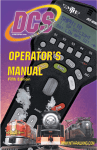
DCS Remote Control
This is the device you will use the most when controlling your trains. It communicates
with the TIU via a 900MHz signal in much the same manner as your cordless phone
communicates with its base. The remote does not talk directly to the locomotive or
accessory you are controlling.
MICROPHONE
LCD DISPLAY
SOFTKEYS -
Activate locomotive features
B/L - Screen backlight on/off
AUX - Auxiliary menu
ACC - Accessory menu
BELL - Rings bell
ENG - Engine menu
(to select and control engines)
MENU - Access 4 main menus
Sound, Control, System, Advanced
LABOR/REV UP OR DRIFT/REV DN
Makes an engine sound like
it's working harder or easier
BOOST/BRAKE
Temporarily Raises or Lowers Speed
SMOKE - Turns smoke unit on & off
VOL+ - Globally increases all sounds
ENG SND - Silences engine sounds
VOL- - Globally decreases all sounds
HDLT - Turns headlights on & off
PROTOCAST - Activates Proto-Cast™
READ - Search for TIUs, AIUs and
Proto-Sound® 2.0 Engines on the track
MIC - Turns
Proto-Dispatch™ on & off
TR - Track menu
(Access various tracks / blocks on your layout)
SW - Switch menu
W/H - Blows whistle/horn
THUMBWHEEL - Throttle &
selection (scroll & press) tool
DIR Changes locomotive direction
CPLR-F/CPLR-R
Fires front & rear couplers
START UP - Activates sound,
smoke & lights
SHUT DOWN - Deactivates
all sound, smoke & lights
PFA - Activates
Passenger/Freight Sounds
E-STOP - Cuts power to
all tracks
DOPPLER - Activates
Proto-Doppler™
Programming Port - Tether
attaches between remote and TIU for
programming new software features
DCS Command System User’s Guide
7
Introduction To DCS
The Track Interface Unit
Also known as the TIU, the Track Interface Unit is the brains behind the DCS system.
Connected between the transformer and the track, the TIU receives signals from the
DCS remote control and relays those signals to each train you are controlling via the rails.
The type of signal relayed to the train depends on the operating mode at the time. If
operating conventionally, the TIU will raise and lower track voltage to control engine
speed. If operating in command mode, the TIU will send a digital signal to each train
you are controlling via the track rails.
This digital signal is very powerful and contains a lot of information much like the digital
signals used in today’s high tech products. These digital signals are what allow DCS to
perform the hundreds of functions designed into the system.
ATTENTION
TIU contains internal
fuses. If there is no
output, open the case (6 Screws)
and check the fuse.
More information on Page 133.
8
DCS Command System User’s Guide
Introduction To DCS
The Accessory Interface Unit
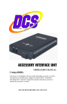
The Accessory Interface Unit, also known as the AIU, plugs into the TIU and controls
any accessory or switch wired to it. Each AIU can control up to 10 switches and 10
accessories and features the ability to turn the accessory on or off, or activate it momentarily.
The AIU essentially acts as a large relay and simply replaces the manual switches that are
normally used to turn on and off model railroading accessories. Connection to the TIU
is done through a special cable (included with the AIU) and up to five AIUs can be daisychained to one TIU.
ATTENTION:
Connecting the TIU to the AIU output may cause damage to earlier
model AIU’s.
ACC
IN = Armature of Relay
1 = NO (normally open)
2 = NC (normally closed)
DCS Command System User’s Guide
SW
IN = AC Common
1 = Straight
2 = Curved
9
Introduction To DCS
Recommended Wiring Method
It is important for good operation to make the most efficient use of the power and digital signal available on your track. Poor wiring and bad connections offer resistance and
can interfere with receipt of the DCS signal and limit the number of engines and cars
you can run on your track. Be sure to use proper wire (we recommend 16-gauge or larger paired wire, like speaker wire) and good connections (good connections mean crimp or
solder).
Because center rail blackening is not conductive, you may find that the blackening on
your track creates resistance that drains power and signal. If so, use Scotch-Brite®, finegrit sandpaper, or an LGB® track cleaning block to clean the blackening off the top of
your center rail.
Advanced wiring information and diagrams, including wiring for layouts using blocks for
conventional operation, are located in the “Universal Locomotive and Accessory
Operation” section of this manual.
Optimal Performance Wiring Principles:
-
-
-
10
Use 16-gauge or larger paired wire (such as speaker wire)
Use a star pattern (home run wiring) to wire directly from the TIU to each
lock-on
Use a terminal block to carry power and signal from one TIU channel to
multiple lock-ons
Avoid common bus wiring
Solder for tight connections (not required)
Clean the blackening off the top of the center rail (if necessary)
Power accessories and turnouts via auxiliary, not track, power
Place a lock-on (or wire directly to track) approximately every 25 linear feet,
both center and one outside rail
DCS Command System User’s Guide
Introduction To DCS
Recommended Wiring Method
Maximum Power Input
0-22VAC,190VAC, 10AMP
OR
0-24VDC, 10AMP
Note: This very quick wiring scheme (through the Fixed In 1 and Fixed Out 1
inputs) allows for operation of the connected loop of track in DCS command mode
only. Please see the “Advanced Connection” section of this manual in the “Universal
Operation” chapter for all the wiring options if you have more complex wiring and
operational needs, including conventional mode and TMCC operation.
DCS Command System User’s Guide
11
Introduction To DCS
Recommended Wiring Method
Optional Additional Equipment Shown:
M.T.H. Terminal Block (Item No. 50-1014)
The screws in each terminal strip of this terminal block are electrically connected to
one another, making it easy to wire the TIU’s output into the binding posts and then
wire out to several lock-ons from different terminal pairs.
Transformer Note: Although we do not recommend using the DCS System with homemade transformers or those that put out more than 12 amps, virtually any commercial
AC hobby power supply will work with DCS. (See Transformer Compatibility Chart,
p. 114) Bear in mind that as you begin to run more and longer trains together, you
need to have lots of power on the track. For this reason, we recommend that railroaders with large layouts and long trains use M.T.H.’s Z-4000®(Item No. 40-4000), which
is the most powerful UL-rated transformer on the market.
12
DCS Command System User’s Guide
Introduction To DCS
Recommended Wiring Method - Older Transformers
Older transformers, like the Lionel postwar ZW or KW models
employ a bi-metallic strip to act as a circuit breaker. The strip
responds to heat as high current flows through the transformer. If
enough heat is generated by the high current, the strip will open the
circuit and prevent further current from flowing out of the transformer. The bi-metallic strip is not a precise overload protection
device and does not measure the current. As a result, it may not trip
when excessive amps are being generated by the short circuit. Should
the strip thus fail to trip, excessive and potentially harmful current
could be sent through the TIU.
MTH therefore recommends that any user employing an older transformer that does not
meet today’s U.L. standards install inline fuses or circuit breakers between the transformer
and the TIU input channels. An AG3C “fast-acting” or “fast-blow” fuse rated at 15 amps
would be suitable protection. These can be obtained from most hardware or electronic
stores including Radio Shack. Users will also need an inline fuse holder to house the fuse.
Radio Shack sells a heavy duty model, part number 27-1217.
Recommended Wiring Method - Electronic Transformers
Any transformer employing two parts, a brick
(step down transformer) and a controller (used
to vary the voltage output) may cause operational problems due to low power or poor DCS
signal. To correct this problem, MTH recommends connecting only the brick to the TIU
inputs. In addition, check the output voltage of
the transformer; it should not exceed 22 volts
(or 18 volts if lighted cars are used on the track).
Brick
TIU
Controller
Brick
When using the Z-500, Z750 or
Z1000 electronic type transformer use
an adapter cable, MTH item 50-1017,
to connect the brick directly to the
TIU input as shown below. DO NOT
use the controller portion of an electronic type transformer.
TIU/Barrel Jack Adapter Cable
(50-1017)
DCS Command System User’s Guide
13