1
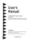
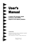
Introduction
I/O Shield Connector
The board is equipped with an I/O back panel. Please use the appropriate I/O
shield (figure 3).
Joystick/Midi port
parallel port
PS/2 Mouse
USB port
PS/2
KEYBOARD
COM1
COM2
Figure 3: I/O back panel layout
Speaker
Line_in
MIC
Power-On/Off (Remote)
The board has a single 20-pin connector for ATX power supplies. For ATX power
supplies that support the Remote On/Off feature, this should be connected to the
systems front panel for system Power On/Off button. The systems power On/Off
button should be a momentary button that is normally open.
The board has been designed with “Soft Off" functions. You can turn Off the
system from one of two sources: The first is the front panel Power On/Off
button, and the other is the "Soft Off" function (coming from the M/B’s onboard
circuit controller) that can be controlled by the operating system such as Windows®
95/98/SE/ME or Windows®2000.
ATX
POWER SUPPLY
J3
Case (chassis) Power
ON/OFF button (J 3)
Figure 4: Simple ATX Power ON/OFF Controller
Page 1-7