1
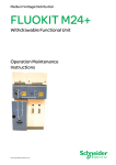
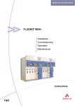
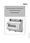
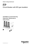
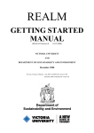
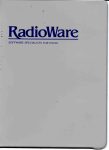
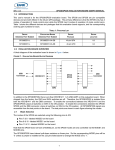
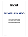
Training Panel System
+
+
+
+
+
+
The AM Transceiver Trainer is designed to
teach and demonstrate the principles of AM
transmissions and reception system.
AM Transceiver Trainer
PT 94329
The trainer consist of modular block to
enable the student to learn AM Transmitter
and Receiver system in modular way. The
panel type constructions are easy to handle
by student when conducting the experiment.
The trainer completed with fault simulator
and fault indicator. The fault simulator can be
used to teach troubleshooting.
ELECTRONIC | Communication and RF
Features
Completed with test point to show the wave
form of AM signal system.
All input and output on each panel are
equipped with robust 4-mm sockets for easy
connection.
Complete with comprehensive Experiment
manual book to guide the student step by
step in conducting experiments.
Covered Topics
2
TE07001E
Power Supply
2
TE07002E
X'tal Oscillator
2
TE07003E
Buffer
2
TE07004E
Driver/Power RF
2
TE07005E
Modulator
2
TE07006E
Tuner & Mixer
2
TE07007E
IF Section
2
TE07008E
Audio Amplifier
Specification
!
Power Supply [ PTE-017-08 ]
- Input voltage
: 220V, 50Hz
- Output voltage
: +15VDC, 2.5A
!
Receiver Section [ PTE-017-05] ; [ PTE-017-06 ]
- Frequency range
: SW1 : 3 – 7 MHz;
SW2 : 7 – 12 MHz
- Electrowave mode : AM / CW
- IF frequency
: 455kHz
- Sensitivity
: 2µV (approx.)
- Input voltage
: +15VDC
!
Transmitter Section [ PTE-017-01] ; [ PTE-017-02 ] ; [PTE-017-03] ;
[PTE-017-04]
- Frequency
: 3.579MHz (X'tal controlled oscillator)
- RF power output
: 5W (approx.)
- Transmission mode : DSB
- Output load
: 50?
- Input voltage
: 15VDC
!
Audio Amplifier [ PTE-017-07 ]
- Input voltage
: +15VDC
- Power output
: 2W (approx.)
For further detail information, please contact us at
Jl. Pudak No. 4 Bandung 40113, Jawa Barat, Indonesia | Phone: +62.22.723.1046 | Fax.: +62.22.720.7252 | E-mail: [email protected] | Website: www.pudak.com
21
Communication and RF | ELECTRONIC
Training Panel System
PT 94329 AM Transceiver Trainer
consists of
Cat. No.
Description
Qty.
PTE-017-01
PTE-017-02
PTE-017-03
PTE-017-04
PTE-017-05
PTE-017-06
PTE-017-07
PTE-017-08
FEL 220 01
GSE 230 05
FLS 20.02/097
KAL 99/40-050
KAL 99/30-050
KAL 99/10-075
KAL 99/20-075
T07S-01E
GSN 240
X-Tal Oscillator
Buffer
Driver / Power RF
Modulator
Tuner & Mixer
IF Section
Audio Amplifier
Power Supply
Telescopic Antenna
BNC to BNC Connecting Coaxial Cable
Connecting Cross
Connecting Lead 50cm, Yellow
Connecting Lead 50cm, Blue
Connecting Lead 75cm, Black
Connecting Lead 75cm, Red
Experiment Manual Book
TPS Frame 600mm
1 pc
1 pc
1 pc
1 pc
1 pc
1 pc
1 pc
1 pc
1 pc
1 pc
30 pcs
20 pcs
6 pcs
2 pcs
2 pcs
1 pc
1 set
Oscillator X'TAL
PTE-017-01
Driver / Power RF
PTE-017-03
Buffer
PTE-017-02
Modulator
PTE-017-04
Tuner and Mixer
PTE-017-05
IF Section
PTE-017-06
Audio Amplifier
PTE-017-07
Power Supply
PTE-017-08
Specifications and illustrations are subject to change without prior notice
22
For further detail information, please contact us at
Jl. Pudak No. 4 Bandung 40113, Jawa Barat, Indonesia | Phone : +62.22.723.1046 | Fax.: +62.22.720.7252 | E-mail : [email protected] | Website: www.pudak.com
Training Panel System
+
+
+
+
+
The FM Transceiver Trainer is designed to
teach and demonstrate the principles of FM
transmissions and reception system.
FM Transceiver Trainer
PT 94330
The trainer consist of modular block to
enable the student to learn FM Transmitter
and Receiver system in modular way. The
panel type constructions are easy to handle
by student when conducting the experiment.
Completed with test point to show the wave
form of FM signal system.
All input and output on each panel are
equipped with robust 4-mm sockets for easy
connection.
ELECTRONIC | Communication and RF
Features
Complete with comprehensive Experiment
manual book to guide the student step by
step in conducting experiments.
Covered Topics
2
TE08001E
Power Supply
2
TE08002E
Stereo MPX Encoder
2
TE08003E
Stereo FM Transmitter
2
TE08004E
Stereo FM Receiver
2
TE08005E
Audio Amplifier
Specification
!
Power Supply [ PTE-018-06 ]
- Input voltage
- Output voltage
!
Receiver Section [ PTE-018-03]
- Frequency range
: 88 – 108 MHz
- IF frequency
: 10.7MHz
- Stereo MPX carrier
: 38kHz
- Stereo pilot
: 19kHz
- Sensitivity
: 2µV (approx.)
- Input voltage
: +15VDC
!
Stereo Multiplexer section [ PTE-018-01 ]
- Stereo sub carrier
: 38kHz
- Internal tone generator : 1kHz & 3kHz (switchable)
- Input voltage
: +15V
!
Transmitter Section [ PTE-018-02 ]
- Frequency
: 95MHz or 100MHz (switchable)
- Frequency stabilization : PLL (Phase Lock Loop)
- RF power output
: 1W (approx.)
- Output load
: 50?
- Input voltage
: +15V
!
Audio Amplifier [ PTE-018-04 ]
- Input voltage
: +15VDC
- Power output
: 2W (approx.)
: 220V, 50Hz
: +15VDC, 2.5A
For further detail information, please contact us at
Jl. Pudak No. 4 Bandung 40113, Jawa Barat, Indonesia | Phone: +62.22.723.1046 | Fax.: +62.22.720.7252 | E-mail: [email protected] | Website: www.pudak.com
23
Communication and RF | ELECTRONIC
Training Panel System
PT 94330 FM Transceiver Trainer
consists of
Cat. No.
Description
Qty.
PTE-018-01
PTE-018-02
PTE-018-03
PTE-018-04
PTE-018-05
PTE-018-06
GSE 230 05
FEL 220 01
FLS 20.02/097
KAL 99/30-050
KAL 99/10-075
KAL 99/10-075
KAL 99/20-075
T08S-01E
GSN 240
Stereo MPX Encoder
FM Transmitter
Stereo FM Receiver
Audio Amplifier
Speaker
Power Supply
BNC to BNC Connecting Coaxial Cable
Telescopic Antenna
Connecting Cross
Connecting Lead 50cm, Yellow
Connecting Lead 50cm, Blue
Connecting Lead 75cm, Black
Connecting Lead 75cm, Red
Experiment Manual Book
TPS Frame 600mm
1 pc
1 pc
1 pc
1 pc
2 pcs
1 pc
1 pc
1 pc
30 pcs
20 pcs
6 pcs
2 pcs
2 pcs
1 pc
1 set
Stereo MPX Encoder
PTE-018-01
FM Transmitter
PTE-018-02
Stereo FM Receiver
PTE-018-03
Audio Amplifier
PTE-018-04
Speaker
PTE-018-05
Power Supply
PTE-018-06
Specifications and illustrations are subject to change without prior notice
24
For further detail information, please contact us at
Jl. Pudak No. 4 Bandung 40113, Jawa Barat, Indonesia | Phone : +62.22.723.1046 | Fax.: +62.22.720.7252 | E-mail : [email protected] | Website: www.pudak.com
Training Panel System
+
+
+
+
+
+
The trainer is designed for presentation and to
practice the principles of basic electronics that
covers; characteristic of electronic component,
regulation, stabilization and protection of power
supply, applied component in circuits, op-amp
and filter circuits.
Basic Electronic Trainer
PT 93120
Complete with assembly board that can be
used to assemble the circuit with available
discrete module's likes resistors, capacitors,
transistors, etc. The connecting cross and
connecting lead are used to connect the circuit
to power supply.
The system consist of modular block that
enable the student to learn the basic
electronic in modular way. The panel
type constructions are easy to handle
by student when conducting the
experiment.
ELECTRONIC | Electronic in Basic Concept
Features
All inputs and outputs on each
panel are equipped with robust 4mm sockets for easy connection.
Connecting leads, connecting
cross and other connecting device
are supplied in sufficient quantity to
do all experiments.
Complete with comprehensive Experiment
manual book to guide the student step by step
in conducting experiments.
Covered Topics
2
2
2
2
2
2
2
2
2
2
2
2
2
2
2
EE02001
EE02002
EE02003
EE02004
EE02005
EE02006
EE02007
EE02008
EE02009
EE02010
EE02011
EE02012
EE02013
EE02014
EE02015
2
EE02016
EE02017
2
EE02018
2
EE02019
2
EE02020
EE02021
EE02022
2
2
2
Introduction to Electronics
Ohm's Law
Thevenin's Theorem 1
Thevenin's Theorem 2
The Theorem of Superposition
Series Coupled Resistance and Voltage Divider
Parallel Coupled Resistance and Current
Divider
Wheatstone Bridge
Non-linear Resistance
Capacitors and Resistors Coupled in Series
AC Signals
The Influences of AC Signals on Resistors
The Influences of AC Signals on Coils
The Influences of AC Signals on Capacitor
Series Coupled RLC and Series Coupled
Resonance
Series Coupled Oscillator Circuit
The Influence of AC Signals on Parallel RC
Circuits
The Influences of AC Signals on Parallel RL
Circuits
Parallel Coupled RLC and Parallel
Resonance
Parallel Coupled Oscillator Circuits
Filter
Response of Integrator and Differentiator
Circuit on Square Waves
2
EE02023
2
EE02024
EE02025
EE02026
EE02027
EE02028
EE02029
EE02030
EE02031
EE02032
EE02033
EE02034
EE02035
EE02036
EE02037
EE02038
EE02039
EE02040
EE02041
EE02042
EE02043
EE02044
EE02045
EE02046
EE02047
2
2
2
2
2
2
2
2
2
2
2
2
2
2
2
2
2
2
2
2
2
2
2
Response of Integrator and Differentiator
Circuits on Triangle Waves
Common Emitter Transistor Amplifier
Common Collector Transistor Amplifier
Transistor as a Switch
Schmitt Trigger
Mono Stable Multivibrator
Bistable Multivibrator
Astable Multivibrator
RC Coupled Amplifier
Direct Coupled Amplifier
Direct Coupled with Complementary Transistor
Common Source FET Amplifier
Common Drain FET Amplifier
Op-Amp as Voltage Follower
Non-Inverting Op-Amp Amplifier
Inverting Op-Amp Amplifier
Uni-Junction Transistor
DIAC
SCR and TRIAC
Half Wave Rectifier
Full Wave Rectifier
Power Control Using SCR
Characteristic of Electrical Sources
Current Sources Employing FET
Current Sources Employing Bipolar Transistor
For further detail information, please contact us at
Jl. Pudak No. 4 Bandung 40113, Jawa Barat, Indonesia | Phone: +62.22.723.1046 | Fax.: +62.22.720.7252 | E-mail: [email protected] | Website: www.pudak.com
25
Electronic in Basic Concept | ELECTRONIC
Training Panel System
Specification
!
Assembly Board for TPS Panel [ GSE 110 ]
- Mountable to standard frame, used to assemble the
experiment circuits from modular component
- 24 socket grids with 24 conducting squares and 216 sockets
6 socket grids with 36 sockets
- 2 conducting paths with 18 sockets each.
- Dimensions
: 297 × 300 mm
!
Power Supply [ PTE-005-01 ]
- Output voltage
- Input voltage
- Output connections
- Dimension
!
: DC 5V / 1A ; 15V / 1A ; -15V / 1A
: AC 220V, 1 phase 50Hz
: 4mm sockets
: 114 × 297 mm
Voltage/Current Source [ PTE-005-02 ]
- Voltage source
: DC Variable 0 up to 12V / 250mA
- Current source
: 0 up to 500mA
- Input voltage
: 220V, 1 phase 50Hz
- Output connections
: 4mm sockets
- Dimension
: 114 × 297 mm
!
Basic Meter [ KAL-41 ]
- Amperemeter, range
- Voltmeter, range
!
Section Boxes, consist of:
- Diode 1A, Diode Zener, DIAC, LED
- Resistors, Potentiometers
- Transistors, TRIAC, SCR, FET
- LDR, NTC, PTC
- Op-Amp
- Toggle Switches
- Capacitors
- UI Core with 500 and 1000 Winding Coil
: 100uA — 100mA — 1A and 5A (DC)
: 100mV — 1V — 10V and 50V (DC)
PT 93120 Basic Electronic Trainer
consists of
Cat. No.
Description
GSE 110
PTE-005-01
PTE-005-02
KAL-41
PTE-005-03
PEO 339 01
PEO 341 03
PEO 339 03
PEO 339 05
PEO 339 07
PEO 339 08
PEO 339 10
PEO 339 11
PEO 344 01
PEO 339 13
PEO 339 14
PEO 339 15
PEO 339 16
PEO 339 17
PEO 339 19
PEO 339 20
PEO 339 21
PEO 339 22
PEO 339 23
PEO 339 24
PEO 339 25
PEO 339 32
PEO 339 35
PEO 339 36
PEO 339 42
Assembly Board for TPS Panel
Power Supply
Voltage/Current Source
Basic Meter
Discreet Component Container - 1
Resistor 1? , 0.5W
Resistor 3.3? , 2W
Resistor 10? , 0.5W
Resistor 22O, 0.5W
Resistor 47O, 0.5W
Resistor 56O, 0.5W
Resistor 100O, 0.5W
Resistor 150O, 0.5W
Resistor 220O, 0.5 W
Resistor 270O, 0.5W
Resistor 330O, 0.5W
Resistor 390O, 0.5W
Resistor 470O, 0.5W
Resistor 560O, 0.5W
Resistor 1kO, 0.5W
Resistor 1,5kO, 0.5W
Resistor 2,2kO, 0.5W
Resistor 3,3kO, 0.5W
Resistor 4,7kO, 0.5W
Resistor 10kO, 0.5W
Resistor 12kO, 0.5W
Resistor 47kO, 0.5W
Resistor 82kO, 0.5W
Resistor 100kO, 0.5W
Resistor 470kO, 0.5W
Qty.
2 pcs
1 pc
1 pc
2 pcs
1 set
1 pc
1 pc
2 pcs
1 pc
1 pc
1 pc
2 pcs
1 pc
1 pc
1 pc
1 pc
1 pc
1 pc
1 pc
4 pcs
2 pcs
1 pc
1 pc
2 pcs
2 pcs
1 pc
1 pc
1 pc
2 pcs
1 pc
Power Supply
PTE-005-01
Cat. No.
PEO 339 44
FLS 20.04/101
PEO 102 02
PEO 102 03
PEO 102 04
FLS 20.07/103
FET 23.04
PEL 222
PEO 372 01
PEO 372 03
FLS 28.08/101
PEO 322 03
PTE-005-04
FET 23.05
PEO 411 02
PEO 411 03
PEO 412 01
PEO 396 23
PEO 396 09
PEO 396 10
PEO 396 20
FET 23.01
PEO 360 11
PEO 365 03
PEO 370
PEO 513
PEO 511 01
PEO 378 05
PEO 378 04
PEO 382 01
PTE-005-05
FEM 21.00
FEM 21.01/500
FEM 21.01/102
PEO 512
PEO 514
PEO 503 03
PEO 503 02
GSE 220
FLS 20.31/27
GSE 220 04
GSE 221 02
PTE-005-06
FLS 20.14/112
FLS 20.13/111
PEO 500 01
PEO 500 02
FLS 20.02/097
KAL 99/40-030
KAL 99/10-050
KAL 99/20-050
KAL 99/30-050
E02S-01E
GSN 240
Voltage/Current Source
PTE-005-02
Description
Resistor 1MO / 0.5W
SPST Toggle Switch
Incandescent Lamp 3V + Lamp Holder E10
Incandescent Lamp 6V + Lamp Holder E10
Incandescent Lamp 12V + Lamp Holder E10
Lamp Holder E10
Neon Lamp
Amperemeter Adapter
Red LED
Green LED
Potentiometer 1kO, 0.25W
Potentiometer 100kO, 0.25W
Discreet Component Container - 2
LDR
Capacitor Non Polar 100nF
Capacitor Non Polar 470nF
Capacitor Tantalum 1µF/35V
Capacitor Electrolyte 1µF/16V
Capacitor Electrolyte 10µF/35V
Capacitor Electrolyte 100µF/35V
Capacitor Electrolyte 2200µF/35V
Diode 1N4002
Diode 1N60
Diode Zener 5V, 0.25W
DIAC DB3
SCR C106
TRIAC BT137D
Transistor BC 547
Transistor BC 556
FET SK-125
Discreet Component Container - 3
U & I Core
Coil 500 turns
Coil 1000 turns
UJT 2N246
Operational Amplifier LM 741
SPDT Toggle Switch
DPDT Toggle Switch
Battery Holder 1,5V
Battery 1,5V
Battery Holder 9V
Battery 9V
Discreet Component Container - 4
Bar Magnet
Bimetal (set)
NTC
PTC
Connecting Cross
Connecting Lead 30cm, Yellow
Connecting Lead 50cm, Black
Connecting Lead 50cm, Red
Connecting Lead 50cm, Blue
Experiment manual Book
TPS Frame 600mm
Qty.
1 pc
2 pcs
2 pcs
2 pcs
1 pc
3 pcs
1 pc
3 pcs
1 pc
1 pc
2 pcs
1 pc
1 set
1pc
1 pc
1 pc
1 pc
1 pc
5 pcs
2 pcs
1 pc
4 pcs
1 pc
1 pc
1 pc
1 pc
1 pc
3 pcs
1 pc
1 pc
1 set
1 pc
1 pc
1 pc
1 pc
1 pc
1 pc
1 pc
2 pcs
2 pcs
1 pc
1 pc
1 set
1 pc
1 pc
1 set
1 set
40 pcs
30 pcs
10 pcs
10 pcs
20 pcs
1 pc
1 set
Specifications and illustrations are subject to change without prior notice
26
For further detail information, please contact us at
Jl. Pudak No. 4 Bandung 40113, Jawa Barat, Indonesia | Phone : +62.22.723.1046 | Fax.: +62.22.720.7252 | E-mail : [email protected] | Website: www.pudak.com
Training Panel System
+
+
+
+
+
+
+
+
The trainer is designed for general purpose
training that offers ability to perform
variation design of circuit and experiment
function.
Laboratory Breadboard
PT 93132
The trainer provides jumper wires and a
large size of breadboard for quick
assembly of experiment circuit.
Desktop type, easy to handle.
Complete with power supply,
function generator, voltmeter,
amperemeter, speaker, buzzer and
decade capacitors to support the
experiment.
ELECTRONIC | Electronic in Basic Concept
Features
All inputs and outputs are equipped with
robust 4-mm sockets for easy connection.
Connecting leads, connecting cross and
other connecting device are supplied in
sufficient quantity to do all experiments.
Complete with comprehensive Experiment
manual book to guide the student step by
step in conducting experiments.
The teacher and student can make their
own experiments.
Specification
!
Covered Topics
2
EE03001
Transistor as a Switch
2
EE03002
Schmitt Trigger
2
EE03003
Op-Amp as Voltage Follower
2
EE03004
Non-Inverting Op-Amp Amplifier
2
EE03005
Inverting Op-Amp Amplifier
2
EE03006
Mono Stable Multivibrator
2
EE03007
Bistable Multivibrator
2
EE03008
Astable Multivibrator
Desktop Module [ PTE-013-01 ], equipped with:
- Project board
-Standard breadboard, mounted on desktop, used to
assemble the experiments circuits from discrete component
- Size: 175 × 134 × 8 mm
- Power Supply
- Output
: +5VDC / 1A
Variable 0 – 60VDC / 500mA
30VAC / 250mA CT
- Input
: 220VAC, 1 phase 50Hz
- Output connections: 4mm
- Function Generator
- Frequency
: 100Hz – 10KHz
- Decade Attenuation Control 10mV, 100mV and 1V
- Sine Wave and Triangle Wave output
- DC Voltmeter
- Range
: 0 – 30 V
- DC Amperemeter
- Range
:0–3A
- Decade capacitor
: 0 – 99 nF
- Speaker
: 2¼", 8? , 0.5W
- Buzzer
: 12V
- Switches are SPDT Toggle Switch, SPST Toggle Switch,
Push-On
!
Container Box [ PTE-013-02], consist of:
- Diode 1A, ZD, LED
- Resistors, Potentiometers
- Transistors
- Op-Amp
- Capacitors
For further detail information, please contact us at
Jl. Pudak No. 4 Bandung 40113, Jawa Barat, Indonesia | Phone: +62.22.723.1046 | Fax.: +62.22.720.7252 | E-mail: [email protected] | Website: www.pudak.com
27
Electronic in Basic Concept | ELECTRONIC
Training Panel System
PT 93132 Laboratory Breadboard
consists of
Cat. No.
Description
PTE-013-01
PTE-013-02
PEO 394 01
PEO 394 02
PEO 394 03
PEO 394 04
PEO 394 05
PEO 394 06
PEO 394 07
PEO 394 08
PEO 394 09
PEO 394 10
PEO 394 11
PEO 394 12
PEO 390 01
PEO 390 02
PEO 390 03
PEO 390 05
PEO 390 08
PEO 390 04
PEO 390 09
PEO 390 10
PEO 390 11
PEO 331 03
PEO 331 06
PEO 331 09
PEO 331 10
PEO 331 11
PEO 331 15
PEO 331 19
PEO 331 20
PEO 331 21
PEO 331 24
PEO 331 26
PEO 331 27
PEO 331 28
PEO 331 34
PEO 331 38
PEO 331 39
PEO 331 40
PEO 331 44
PEO 331 47
PEO 331 48
PEO 331 49
FLS 20.08/101
FLA 20.08/103
PEO 322 03
PEO 361 03
PEO 361 09
PEO 361 11
PEO 373 01
PEO 377 02
PEO 380 01
PEO 380 02
PEO 380 03
PEO 380 04
PEO 514 01
PEO 514 02
PEO 180 01
PEO 180 02
GSE 234 01
GSE 234 02
GSE 234 03
GSE 234 04
E03S-01
Desktop Module
Container Box, consist of:
Capacitor 1nF Non Polar
Capacitor 2.2nF Non Polar
Capacitor 4.7nF Non Polar
Capacitor 6.8nF Non Polar
Capacitor 10nF Non Polar
Capacitor 22nF Non Polar
Capacitor 47nF Non Polar
Capacitor 68nF Non Polar
Capacitor 100nF Non Polar
Capacitor 220nF Non Polar
Capacitor 470nF Non Polar
Capacitor 680nF Non Polar
Capacitor 1µF, 16V Electrolyte
Capacitor 2,2µF, 16V Electrolyte
Capacitor 4,7µF, 16V Electrolyte
Capacitor 10µF, 16V Electrolyte
Capacitor 22µF, 16V Electrolyte
Capacitor 47µF, 16V Electrolyte
Capacitor 100µF, 16V Electrolyte
Capacitor 220µF, 16V Electrolyte
Capacitor 470µF, 16V Electrolyte
Resistor 10O, 0.5 W
Resistor 33O, 0.5 W
Resistor 68O, 0.5 W
Resistor 82O, 0.5 W
Resistor 100O, 0.5 W
Resistor 330O, 0.5 W
Resistor 680O, 0.5 W
Resistor 820O, 0.5 W
Resistor 1kO, 0.5 W
Resistor 3.3kO, 0.5 W
Resistor 6.8kO, 0.5 W
Resistor 8.2kO, 0.5 W
Resistor 10kO, 0.5 W
Resistor 33kO, 0.5 W
Resistor 68kO, 0.5 W
Resistor 82kO, 0.5 W
Resistor 100kO, 0.5 W
Resistor 330kO, 0.5 W
Resistor 680kO, 0.5 W
Resistor 820kO, 0.5 W
Resistor 1MO, 0.5 W
Variable Resistor 1kO
Variable Resistor 10kO
Variable Resistor 100kO
Diode 1N4002
Diode 1N4148
Diode 1N60
LED 5mm, Red
Transistor BC 108
Transistor C 9012
Transistor C 9014
Transistor TIP 42C
Transistor TIP 41
Operational Amplifier UA 741
IC Timer LM 555
Single Core Cable Ø 1mm, Red
Single Core Cable Ø 1mm, Black
Connecting Lead 20 cm, Red
Connecting Lead 20 cm, Blue
Connecting Lead 20 cm, Yellow
Connecting Lead 20 cm, Black
Experiment Manual Book
Qty.
1 set
1 set
2 pcs
2 pcs
2 pcs
2 pcs
2 pcs
2 pcs
2 pcs
2 pcs
2 pcs
2 pcs
2 pcs
2 pcs
2 pcs
2 pcs
1 pc
2 pcs
2 pcs
1 pc
2 pcs
2 pcs
1 pc
10 pcs
10 pcs
10 pcs
10 pcs
10 pcs
10 pcs
10 pcs
10 pcs
10 pcs
10 pcs
10 pcs
10 pcs
5 pcs
5 pcs
5 pcs
5 pcs
5 pcs
5 pcs
5 pcs
5 pcs
5 pcs
2 pcs
2 pcs
2 pcs
5 pcs
5 pcs
2 pcs
4 pcs
3 pcs
3 pcs
3 pcs
1 pc
1 pc
2 pcs
1 pc
5m
5m
30 cm
30 cm
30 cm
30 cm
1 pc
EE03001 | Transistor as a Switch
EE03004 | Op-Amp as Voltage Follower
EE03008 | Astable Multivibrator
Specifications and illustrations are subject to change without prior notice
28
For further detail information, please contact us at
Jl. Pudak No. 4 Bandung 40113, Jawa Barat, Indonesia | Phone : +62.22.723.1046 | Fax.: +62.22.720.7252 | E-mail : [email protected] | Website: www.pudak.com
Training Panel System
+
+
+
+
+
+
The trainer is designed for presentation and
to practices the principles of basic
electronic applications that covers;
regulation, stabilization and protection of
power supply, applied component in
circuits and op-amp circuit.
Circuit Application Trainer
PT 94123
Completed with assembly board, that can
be used to assemble the circuit with
available discrete module's likes resistors,
capacitors, transistors, etc. The connecting
cross and connecting lead are used to
connect the circuit to power supply.
The system consist of modular block that
enable the student to learn the basic
electronic in modular way. The panel type
constructions are easy to handle by student
when conducting the experiment.
ELECTRONIC | Electronic in Basic Concept
Features
All inputs and outputs on each
panel are equipped with
robust 4-mm sockets for easy
connection.
Connecting leads, connecting
cross and other connecting
device are supplied in sufficient
quantity to do all experiments.
Complete with comprehensive Experiment
manual book to guide the student step by
step in conducting experiments.
Specification
Covered Topics
2
EE05001
Common Emitter Transistor Amplifier
2
EE05002
Common Collector Transistor Amplifier
2
EE05003
Complementary Push Pull Amplifier
2
EE05004
Differential Transistor Amplifier
2
EE05005
Op-Amp as Voltage Follower
2
EE05006
Op-Amp as Comparator
2
EE05007
Op-Amp as Integrator
2
EE05008
Transistor as a Switch
2
EE05009
Astable Multivibrator
2
EE05010
Phase Shift Oscillator
2
EE05011
Triangle Wave Generator
2
EE05012
UJT Pulse Generator
2
EE05013
Bistable Multivibrator
2
EE05014
Staircase Generator
2
EE05015
Light Operated Alarm
2
EE05016
Delay Circuit
2
EE05017
Temperature Operated Switch
2
EE05018
Schmitt Trigger
2
EE05019
Light Operated Flasher
2
EE05020
Voltage Regulator
!
Assembly Board for TPS Panel [ GSE 110 ]
- Mountable to standard frame, used to assemble the
experiments circuits from modular component
- 24 socket grids with 24 conducting squares and 216 sockets
6 socket grids with 36 sockets
- 2 conducting paths with 18 sockets
- Each dimensions: 297 × 300 mm
!
Power Supply [ PTE-015-01 ]
- Output voltage
: DC 5V / 1A ; 15V / 1A ; -15V / 1A
- Input voltage
: AC 220V, 1 phase 50Hz
- Output connections : 4mm sockets
- Dimension
: 114 × 297 mm
!
Power Supply Variable [ PTE-015-02 ]
- Output voltage
: DC Variable 0 up to 12V / 250mA
- Input voltage
: AC 220V, 1 phase 50Hz
- Output connections : 4mm sockets
- Dimension
: 114 × 297 mm
!
Staircase Generator [ PTE-015-03 ]
- Input voltage
: +15 VDC, -15 VDC
- Output connections : 4mm sockets
- Dimension
: 114 × 297 mm
!
Basic Meter [ KAL-41 ]
- Amperemeter, range : 100µA – 100mA – 1A and 5A ( DC)
- Voltmeter, range
: 100mV – 1V – 10V and 50V (DC)
!
Section Boxes, consist of:
- Diode bridge 1A, Diode 1A, ZD, DIAC, LED
- Regulator
- Resistors, Potentiometers
- Transistors
- Op-Amp
- Switch Change-Over SPDT
- Buzzer
- Relay
For further detail information, please contact us at
Jl. Pudak No. 4 Bandung 40113, Jawa Barat, Indonesia | Phone: +62.22.723.1046 | Fax.: +62.22.720.7252 | E-mail: [email protected] | Website: www.pudak.com
29
Electronic in Basic Concept | ELECTRONIC
Training Panel System
PT 94123 Circuit Application Trainer
consists of
Cat. No.
Description
GSE 110
PTE-015-01
PTE-015-02
PTE-015-03
KAL-41
PTE-015-04
PEO 339 10
PEO 339 15
PEO 339 16
PEO 339 19
PEO 339 20
PEO 339 21
PEO 339 22
PEO 339 23
PEO 339 24
PEO 339 32
PEO 339 33
PEO 339 35
PEO 339 36
PEO 339 37
PEO 339 38
PEO 339 42
FET 23.02 / 001
PEO 396 09
PEO 396 10
PEO 339 21
PEO 396 22
FET 23.05
PEO 516
FET 23.01
FLS 20.04/101
PEO 310 01
PTE-015-05
PEO 378 04
PEO 378 05
FET 23.03/139
FET 23.03/140
PEO 514
PEO 517
PEO 515
PTE-015-06
PEO 500 01
FLS 20.08/11
PEO 322 04
PEO 102 03
FEM 21.00
PEO 372 03
PEO 372 01
PEO 512
FLS 20.02/097
KAL 99/40-030
KAL 99/10-050
KAL 99/20-050
KAL 99/30-050
E05S-01E
GSN 240
Assembly Board for TPS Panel
Power Supply
Variable Power Supply
Staircase Generator
Basic Meter
Container Box I, consists of:
Resistor 100O, 0.5W
Resistor 390O, 0.5W
Resistor 470O, 0.5W
Resistor 1kO, 0.5W
Resistor 1k5O, 0.5W
Resistor 2k2O, 0.5W
Resistor 3k3O, 0.5W
Resistor 4k7O, 0.5W
Resistor 10kO, 0.5W
Resistor 47kO, 0.5W
Resistor 56kO, 0.5W
Resistor 82kO, 0.5W
Resistor 100kO, 0.5W
Resistor 120kO, 0.5W
Resistor 330kO, 0.5W
Resistor 470kO, 0.5W
Capacitor Electrolyte 1µF, 35V
Capacitor Electrolyte 10µF, 35V
Capacitor Electrolyte 100µF, 35V
Capacitor Non Polar 10nF, 35V
Capacitor Non Polar 100nF, 35V
LDR
Buzzer
Diode 1N4002
SPST Toggle Switch
SPDT Toggle Switch
Container Box II, consists of:
Transistor BC 546
Transistor BC 547
Transistor BD 139
Transistor BD 140
Operational-Amplifier LM 741
Phase Inverter (LM741)
Relay 6V
Container Box III, consist of:
NTC
Potentiometer 1kO
Potentiometer 5kO
Incandescent Lamp 6V + Lamp Holder E10
U & I Core
LED, Green
LED, Red
UJT 2N2646
Connecting Cross
Connecting Lead 30cm, Yellow
Connecting Lead 50cm, Black
Connecting Lead 50cm, Red
Connecting Lead 50cm, Blue
Experiment Manual Book
TPS Frame 600mm
Qty.
1 pc
1 pc
1 pc
1 pc
1 pc
1 set
1 pc
1 pc
1 pc
4 pcs
1 pc
1 pc
3 pcs
2 pcs
2 pcs
1 pc
2 pcs
1 pc
3 pcs
1 pc
1 pc
1 pc
1 pc
3 pcs
1 pc
3 pcs
1 pc
1 pc
1 pc
2 pcs
2 pcs
2 pcs
1 set
2 pcs
2 pcs
2 pcs
1 pc
2 pcs
1 pc
1 pc
1 set
1 pc
1 pc
2 pcs
1 pc
1 pc
1 pc
1 pc
1 pc
40 pcs
15 pcs
10 pcs
10 pcs
20 pcs
1 pc
1 set
Variable Power Supply
PTE-015-02
Staircase Generator
PTE-015-03
Container Box I
PTE-015-04
Container Box II
PTE-015-05
Container Box III
PTE-015-06
Specifications and illustrations are subject to change without prior notice
30
For further detail information, please contact us at
Jl. Pudak No. 4 Bandung 40113, Jawa Barat, Indonesia | Phone : +62.22.723.1046 | Fax.: +62.22.720.7252 | E-mail : [email protected] | Website: www.pudak.com
Training Panel System
+
+
+
+
+
+
The trainer is designed to cover the
fundamental concept, theory and
application of operational amplifier with
descriptive and easy to understand.
The trainer supplied with power supplies
required to run the experiments.
Operational
Amplifier Trainer
PT 970232
Desktop type, easy to handle.
All inputs and outputs on each panel are
equipped with robust 4-mm sockets for
easy connection.
Connecting leads, connecting cross
and other connecting device are
supplied in sufficient quantity to do
all experiments.
ELECTRONIC | Electronic in Basic Concept
Features
Complete with comprehensive
Experiment manual book to guide
student step by step in conducting
experiments.
Covered Topics
2
EE07001
Comparator
2
EE07002
Inverting Amplifier
2
EE07003
Voltage Gain in Inverting Amplifier
2
EE07004
Frequency Dependence in Inverting Amplifier
2
EE07005
Voltage Adders
2
EE07006
Subtractors
2
EE07007
Constant Voltage Source Adjustable
2
EE07008
Constant Current Source
2
EE07009
Non Inverting Amplifier
2
EE07010
Voltage Follower
2
EE07011
Differentiator
2
EE07012
Integrator
2
EE07013
Wien-Bridge Oscillator
2
EE07014
High Pass Filter
2
EE07015
Low Pass Filter
Specification
!
Desktop Module [ PTE-023-01 ], equipped with:
- Universal configuration of Operational Amplifier
- Power Supply
- Output
- Input
- Output connections
- Potentiometer 10k?
!
: DC Fixed 3, 6, 9, 12V
: AC 220V, 1 phase 50Hz
: 4mm
and 50k?
Container Box [ PTE-023-02 ], consists of:
- Resistor 470? /1W
- Resistor 1k5? /1W
- Resistor 6k8? /1W
- Resistor 8k2? /1W
- Resistor 10k? /1W
- Resistor 15k? /1W
- Resistor 18k? /1W
- Resistor 22k? /1W
- Resistor 33k? /1W
- Resistor 100k? /1W
- Resistor 470k? /1W
- Capacitor 1nF non polar
- Capacitor 4,7nF non polar
- Capacitor 10nF non polar
- Capacitor 100nF non polar
- Capacitor electrolyte 1µF/16V
- Zener Diode 5,6V / 0,25W
For further detail information, please contact us at
Jl. Pudak No. 4 Bandung 40113, Jawa Barat, Indonesia | Phone: +62.22.723.1046 | Fax.: +62.22.720.7252 | E-mail: [email protected] | Website: www.pudak.com
31
Electronic in Basic Concept | ELECTRONIC
Training Panel System
PT 970232 Operational Amplifier Trainer
consists of
Cat. No.
Description
Qty.
PTE-023-01
PTE-023-02
PEO 340 15
PEO 340 19
PEO 340 23
PEO 340 24
PEO 340 25
PEO 340 26
PEO 340 27
PEO 340 28
PEO 340 29
PEO 340 35
PEO 340 41
PEO 411 04
PEO 411 05
PEO 411 01
PEO 411 02
PEO 395 08
PEO 365 04
FLS 20.02/097
KAL 99/40-030
E07S-01E
Desktop Module, consists of:
Container Box, consists of:
Resistor 470? / 1W
Resistor 1k5? / 1W
Resistor 6k8? / 1W
Resistor 8k2? / 1W
Resistor 10k? / 1W
Resistor 15k? / 1W
Resistor 18k? / 1W
Resistor 22k? / 1W
Resistor 33k? / 1W
Resistor 100k? / 1W
Resistor 470k? / 1W
Capacitor 1nF
Capacitor 4,7nF
Capacitor 10nF
Capacitor 100nF
Capacitor 1µF
Zener Diode 5,6V / 0,25W
Connecting Cross
Connecting Lead 30cm, Yellow
Experiment Manual Book
1 set
1 set
1 pc
1 pc
1 pc
1 pc
1 pc
1 pc
1 pc
1 pc
1 pc
1 pc
1 pc
1 pc
1 pc
1 pc
1 pc
1 pc
1 pc
10 pcs
20 pcs
1 pc
Experiment EE07005 Voltage Adders
Section Boxes
Specifications and illustrations are subject to change without prior notice
32
For further detail information, please contact us at
Jl. Pudak No. 4 Bandung 40113, Jawa Barat, Indonesia | Phone : +62.22.723.1046 | Fax.: +62.22.720.7252 | E-mail : [email protected] | Website: www.pudak.com
Training Panel System
+
+
+
+
+
+
+
The digital trainer is designed as a
teaching aid for digital technology.
The trainer consists of several functional
modules, such as basic gate, flip-flops,
multiplexer, demultiplexer, registers,
counters, adder, comparator, ADC, DAC,
arithmetic logic unit and so on. All digital
function symbols printed referring to
standard IEEE logic symbols.
ELECTRONIC | Digital and Microprocessor
Features
Digital Trainer
PT 93131
All inputs and outputs terminal of digital
function are equipped with LED indicator
to indicate current state of inputs or
outputs terminal.
The modules are equipped with overvoltage and over current protector to
protect module from damage
possibility.
The system consist of modular block
to enable the student to learn the
digital technology in modular way.
The panel type constructions are
easy to handle by student when
conducting the experiment.
All inputs and outputs on each
panel are equipped with robust 4-mm
sockets for easy connection.
Complete with comprehensive
experiment manual book to guide
student step by step in conducting
experiments.
Covered Topics
2
DE01001E
Logic Gates
2
DE01002E
The Boolean Algebra
2
DE01003E
Combinational Logic
2
DE01004E
De Morgan's Law
2
DE01005E
Building Logic Circuit Based on A Truth
Table
2
DE01006E
The Karnaugh Map
2
DE01007E
Adder and Arithmetic Circuits
2
DE01008E
Designing A Logic Circuits
2
DE01009E
Flip-Flop Circuits
2
DE01010E
Multi Vibrator
2
DE01011E
Counter
2
DE01012E
Shift Register
2
DE01013E
Decoder and Encoder
2
DE01014E
Analog to Digital Converter and Digital To
Analog Converter
2
DE01015E
Multiplexer and Demultiplexer
Specification
!
AND Gate Dual Input [ PTE-006-01 ]
- Supply voltage
: +5VDC
- Consist
: 4 Gates/module
!
NAND Gate Dual Input [ PTE-006-02 ]
- Supply voltage
: +5VDC
- Consist
: 4 Gates/module
!
OR Gate Dual Input [ PTE-006-03 ]
- Supply voltage
: +5VDC
- Consist
: 4 Gates/module
!
NOR Gate Dual Input [ PTE-006-04 ]
- Supply voltage
: +5VDC
- Consist
: 4 Gates/module
!
XOR Gate Dual Input [ PTE-006-05 ]
- Supply voltage
: +5VDC
- Consist
: 4 Gates/module
!
XNOR Gate Dual Input [ PTE-006-06 ]
- Supply voltage
: +5VDC
- Consist
: 4 Gates/module
!
NAND Gate Quad Input [ PTE-006-07 ]
- Supply voltage
: +5VDC
- Consist
: 2 Gates/module
!
NOT Gate (Inverter) [ PTE-006-08 ]
- Supply voltage
: +5VDC
- Consist
: 6 Gates/module
!
AND Gate Quad Input [ PTE-006-09 ]
- Supply voltage
: +5VDC
- Consist
: 2 Gates/module
!
RS Flip-Flop [ PTE-006-10 ]
- Supply voltage
: +5VDC
- Consist
: 2 Flip-Flop/module
!
JK Master-Slave Flip-Flop [ PTE-006-11 ]
- Supply voltage
: +5VDC
- Consist
: 2 Flip-Flop/module
Continue
For further detail information, please contact us at
Jl. Pudak No. 4 Bandung 40113, Jawa Barat, Indonesia | Phone: +62.22.723.1046 | Fax.: +62.22.720.7252 | E-mail: [email protected] | Website: www.pudak.com
33
Digital and Microprocessor | ELECTRONIC
Training Panel System
Specification Continued
!
D Flip-Flop [ PTE-006-12 ]
- Supply voltage
: +5VDC
- Consist
: 2 Flip-Flop/module
!
Comparator [ PTE-006-21 ]
- Supply voltage
: +5VDC
- Consist
: 1 Comparator/module
!
Multiplexer 4 bit [ PTE-006-13 ]
- Supply voltage
: +5VDC
- Consist
: 2 Multiplexer/module
!
4 bit ALU [ PTE-006-22 ]
- Supply voltage
: +5VDC
- Consist
: 4 bit ALU/module
!
Demultiplexer 8 bit [ PTE-006-14 ]
- Supply voltage
: +5VDC
- Package
: 1 Demultiplexer/module
!
Analog to Digital Converter [ PTE-006-23 ]
- Supply voltage
: +5VDC, +15VDC, -15VDC
- Consist
: 1 ADC/module
!
BCD to 7 Segments [ PTE-006-15 ]
- Supply voltage
: +5VDC, +15VDC
- Consist
: 1 BCD to 7 Segments/module
!
Digital to Analog Converter [ PTE-006-24 ]
- Supply voltage
: +5VDC, +15VDC, -15VDC
- Consist
: 1 DAC/module
!
4 bit Shift Register [ PTE-006-16 ]
- Supply voltage
: +5VDC
- Consist
: 1 Register/module
!
!
Asynchronous Binary Counter [ PTE-006-17 ]
- Supply voltage
: +5VDC
- Consist
: 1 Counter/module
Pulse Generator [ PTE-006-25 ]
- Supply voltage
: +5VDC
- Consist
: 1 package/module
- Frequency outputs : 1 – 10 Hz or 10 – 100 Hz
- Pulse output
: continues or single
- Direct output or invert output
!
Asynchronous BCD Counter [ PTE-006-18 ]
- Supply voltage
: +5VDC
- Consist
: 1 Counter/module
!
IC Socket [ PTE-006-26 ]
- 16 pin universal ZIP DIP socket
!
!
Syn Up/Dn Counter with Parallel Load [ PTE-006-19 ]
- Supply voltage
: +5VDC
- Consist
: 1 Counter/module
Power Supply [ PTE-006-27 ]
- Supply voltage
: 220V – 240VAC, 50Hz
- Voltage output
: +15V, -15VDC 1A and +5VDC, 4A
!
!
Full Adder [ PTE-006-20 ]
- Supply voltage
: +5VDC
- Consist
: 1 Adder/module
Switch [ PTE-006-28 ]
- Contains 8 switches
PT 93131 Digital Trainer
consists of
Cat. No.
Description
PTE-006-01
AND Gate (Dual Input)
PTE-006-02
NAND Gate
PTE-006-03
OR Gate
PTE-006-04
NOR Gate
PTE-006-05
XOR Gate
PTE-006-06
XNOR Gate
PTE-006-07
NAND Gate
PTE-006-08
NOT Gate
PTE-006-09
AND Gate (Quad Input)
PTE-006-10
RS Flip-Flop
PTE-006-11
JK Master-Slave Flip-Flop
PTE-006-12
D Flip-Flop
PTE-006-13
Multiplexer 4 bit
PTE-006-14
Demultiplexer 8 bit
PTE-006-15
BCD to 7 Segment
PTE-006-16
4 bit Shift Register
PTE-006-17
Asynchronous Binary Counter
PTE-006-18
Asynchronous BCD Counter
PTE-006-19
Syn Up/Dn Counter with Parallel Load
PTE-006-20
Full Adder
PTE-006-21 Compara
tor
PTE-006-22
4 bit ALU
PTE-006-23
Analog to Digital Converter
PTE-006-24
Digital to Analog Converter
PTE-006-25
Pulse Generator
PTE-006-26
IC Socket
PTE-006-27
Power Supply
PTE-006-28
Switch
FLS 20.02/097
Connecting Cross
KAL 99/30-050 Connecting Lead 50cm, Blue
KAL 99/10-050 Connecting Lead 50cm, Black
KAL 99/20-050 Connecting Lead 50cm, Red
D01S-01E
Experiment Manual Book
GSN 245
TPS Frame 1200mm
Qty.
1 pc
1 pc
1 pc
1 pc
1 pc
1 pc
1 pc
1 pc
1 pc
1 pc
1 pc
2 pcs
1 pc
1 pc
2 pcs
2 pcs
1 pc
2 pcs
1 pc
1 pc
1 pc
1 pc
1 pc
1 pc
1 pc
2 pcs
1 pc
1 pc
60 pcs
60 pcs
10 pcs
10 pcs
1 pc
1 set
AND
PTE-006-01
J-K Master Slave Flip-Flop
PTE-006-11
BCD to 7 Segment
PTE-006-16
4 Bit ALU
PTE-006-22
Specifications and illustrations are subject to change without prior notice
34
For further detail information, please contact us at
Jl. Pudak No. 4 Bandung 40113, Jawa Barat, Indonesia | Phone : +62.22.723.1046 | Fax.: +62.22.720.7252 | E-mail : [email protected] | Website: www.pudak.com
Training Panel System
+
+
+
+
+
+
+
+
+
The trainer is designed to teach the
fundamental of 8 bit industrial
microprocessor. Compact model-only on a
single high quality double side board-to
make the trainer easy to carry.
Microprocessor Trainer
PT 980401
No external software needed to use this
trainer, simply type the user program
sequence to the trainer on built in keypad.
Easy to check and change the contents of
the registers on microprocessor.
User's program can run in step by step
mode or continuous running.
ELECTRONIC | Digital and Microprocessor
Features
User's program can be written in assembly
language or BASIC.
All input output lines and microprocessor
buses are available for off-board expansion.
Provide audio tape interface to record user's
program on a cassette and can be reloaded
to the trainer in a simple way.
Wide breadboard area is provided to build
an external circuit.
Complete with comprehensive experiment
manual and user's manual book to guide
student step by step in conducting
experiments.
Covered Topics
Specification
Processor
: Zilog Z-80
2
DE04001E
Introduction to Microprocessor Trainer
2
DE04002E
Data Transfer Experiment
!
ROM
: 4KB
2
DE04003E
Basic Application of Arithmetic And Logic
Operation
!
RAM
: 2KB, expanded to 4KB
!
Programmable input output
: Z80 PIO 16 bit I/O lines
Controller Timer Counter
: Z80 CTC 4 independent timer counter
!
2
DE04004E
Subtract and Adder Instruction
!
2
DE04005E
Loop Program and Branch Instruction
!
Seven Segment
: 6 Digit for data and address display
2
DE04006E
Subroutine and Stack
!
2
DE04007E
Rotate, Shift, Instruction and Multiple
Routine
Speaker
- Impedance
- Power
- Audio drive included
: 8?
: 0.5W
2
DE04008E
Divide Instruction
!
Keypad
: 36 keys for data and function entry
2
DE04009E
Binary to BCD Conversion Program
!
Keypad Template
: BASIC and Assembler
2
DE04010E
BCD to Binary Conversion Program
!
Breadboard
!
Audio Tape Interface
2
DE04011E
Square Program
2
DE04012E
Game
2
DE04013E
Stop Watch
2
DE04014E
Clock
2
DE04015E
Telephone Tone
2
DE04016E
Microcomputer Organ
2
DE04017E
Music Box
For further detail information, please contact us at
Jl. Pudak No. 4 Bandung 40113, Jawa Barat, Indonesia | Phone: +62.22.723.1046 | Fax.: +62.22.720.7252 | E-mail: [email protected] | Website: www.pudak.com
35
Digital and Microprocessor | ELECTRONIC
Training Panel System
PT980401 Microprocessor Trainer
consists of
Cat. No.
Description
Qty.
PT980401
PEL 223 01
PEL 223 02
D04S-01E
D04M-01E
D04M-02E
Microprocessor Trainer Board
Assembler Keypad Template
BASIC Keypad Template
Experiment Manual Book
User's Manual Book
Monitor Source Program Listing Book
1 pc
1 pc
1 pc
1 pc
1 pc
1 pc
Realtime Clock Using IC 555
RS
MOVE
INS
SBR
PC
MONI
RELA
DEL
CBR
REG
INTR
TAPE
WR
STEP
-
DATA
USER
KEY
TAPE
RD
GO
+
ADDR
FOR
▲
TO
▼
SZ.H
.PNC
SZ.H'
PNC'
C
D
E
F
IX
IY
SP
I.IF
8
9
A
B
AF'
BC'
DE'
HL'
4
5
6
7
AF
BC
DE
HL
0
1
2
3
NEXT
.PRINT
INPUT
LET
C
D
E
F
M
P
CALL
STOP
8
9
A
B
<
>
7
Assembler Keypad Template
PEL 223 01
RESET
DEL
?
GOSUB
CLR
?
RET
~
IF
v
THEN
v
**
SAVE
SHIFT
LOAD
CONT
RUN
LIST
ENTER
NEW
GOTO
4
5
6
+
-
*
/
0
1
2
3
BASIC Keypad Template
PEL 223 02
Specifications and illustrations are subject to change without prior notice
36
For further detail information, please contact us at
Jl. Pudak No. 4 Bandung 40113, Jawa Barat, Indonesia | Phone : +62.22.723.1046 | Fax.: +62.22.720.7252 | E-mail : [email protected] | Website: www.pudak.com
Training Panel System
ELECTRONIC | Digital and Microprocessor
Features
+
+
+
+
+
+
+
+
The Microcontroller trainer is designed to
teach the fundamental knowledge of
hardware and software of a
microcontroller.
Microcontroller Trainer
PT 981702
The trainer can be used to demonstrate
various device interfacing with
microcontroller.
Provide test point for investigate write or
read timing sequence of microcontroller
when accessing to another unit.
Investigating can be done by using logic
probe or logic analyzer.
Each peripheral unit equipped with
selectable DIP-switch for easy to change
address of peripheral unit.
Modules are equipped with over voltage
and over current protector to protect
module from damage possibility.
The system consist of modular block to
enable the student to learn the
microcontroller in modular way. The panel
type constructions are easy to handle by
student when conducting the experiment.
All inputs and outputs on each panel are
equipped with robust 4-mm sockets for
easy connection.
Complete with comprehensive experiment
manual book to guide student step by
step in conducting experiments.
Specification
!
8031 Central Processing Unit [ PTE-026-01 ]
- Based on 8031 microcontroller
- Clock system: 11.0592MHz or manual clock by pushbutton
- Program files download via PC USB port (PC not included)
- EPROM program storage replaced by 8Kbytes RAM
- External memory: 8Kbyte
- 2 × 13 bus connectors to connect with other devices
- RS232 converter
!
Parallel Input/Output [ PTE-026-02 ]
- Programmable input output: 3 × 8 bit
- 2 × 13 bus connector to connect with other devices
- Device addressing : selectable by DIP-switch
- Provide test point
!
Serial Input/Output [ PTE-026-03 ]
- Programmable serial input output
- Device addressing : selectable by DIP-switch
- Provide test point
- Provide RS 232
- 2 × 13 bus connectors to connect with other devices
!
Analog to Digital Converter [ PTE-026-04 ]
- Resolution
: 8 bit
- Conversion time
: 100 microseconds
- Voltage input
: -10V – +10V
- Provide test point
- Device addressing : selectable by DIP-switch
- 2 × 13 bus connectors to connect with other devices
!
Digital to Analog Converter [ PTE-026-05 ]
- Resolution
: 8 bit
- Output voltage
: -10V – +10V
- Provide test point
- Device addressing : selectable by DIP-switch
- Provide 2 × 13 bus connectors to connect with other devices
!
LED Matrix [ PTE-026-06 ]
- Input voltage
: +5V
- Large 5 × 7 LED matrix
- Connected by 4mm connector
- Drive by transistor
Covered Topics
2
DE05001E
Introduction to 8031 Central Processing Unit
2
DE05002E
Interfacing with Digital to Analog Converter
2
DE05003E
Interfacing with Analog to Digital Converter
2
DE05004E
Interfacing with Programmable Digital
Peripheral Interface
2
DE05005E
Interfacing with Programmable Serial
Communication Interface
2
DE05006E
Seven Segment
2
DE05007E
LED Matrix
2
DE05008E
Stepper Motor
2
DE05009E
Traffic Light
Continue
For further detail information, please contact us at
Jl. Pudak No. 4 Bandung 40113, Jawa Barat, Indonesia | Phone: +62.22.723.1046 | Fax.: +62.22.720.7252 | E-mail: [email protected] | Website: www.pudak.com
37
Digital and Microprocessor | ELECTRONIC
Training Panel System
Specification Continued
!
Seven Segment [ PTE-026-07 ]
- Common voltage
: +15V
- Large seven segment (two colors)
- Type
: common anode
- Drive by transistor
!
Loud Speaker [ PTE-026-08 ]
- Impedance
: 8?
- Power
: 1W
- Power amplifier
: 1W
!
Power Supply [ PTE-026-09 ]
- Input voltage
: 220V – 240V, 50Hz
- Output voltage
: +15V, 1.5A
+5V, 1.5A
-15V, 0.5A
!
Traffic Light Model [ PTE-MP1-01 ]
- Traffic light model to simulate junction of main road and a
branch/minor road traffic light system
!
Stepping Motor [ PTE-MP1-02 ]
- Unipolar motor stepper
- Built in motor stepper controller:
· Full and half step
· CW and CCW direction
- Controlled by built in controller or external logic control
- Active coil of stepper motor indicated by LED
PT981702 Microcontroller Trainer
consists of
Cat. No.
Description
Qty.
PTE-026-01
PTE-026-02
PTE-026-03
PTE-026-04
PTE-026-05
PTE-026-06
PTE-026-07
PTE-026-08
PTE-026-09
PTE-MP1-01
PTE-MP1-02
GSE 230 15
GSE 230 11
FLS 20.02/097
KAL 99/30-050
KAL 99/10-050
KAL 99/20-050
GSC 700 01
D05S-01E
GSN 245
8031 Central Processing Unit
Parallel Input/Output
Serial Input/Output
Analog to Digital Converter
Digital to Analog Converter
LED Matrix
Seven Segment
Loud Speaker
Power Supply
Traffic Light Model
Stepping Motor
Standard Serial Cable
Expansion Connecting Lead, 2 × 13 pin
Connecting Cross
Connecting Lead 50cm, Blue
Connecting Lead 50cm, Black
Connecting Lead 50cm, Red
CD PT981702 Microcontroller Trainer
Experiment Manual Book
TPS Frame 1200mm
1 pc
1 pc
1 pc
1 pc
1 pc
1 pc
1 pc
1 pc
1 pc
1 pc
1 pc
1 pc
4 pcs
50 pcs
50 pcs
10 pcs
10 pcs
1 pc
1 pc
1 set
8031 Central Processing Unit
PTE-026-01
Parallel Input / Output
PTE-026-02
Serial Input / Output
PTE-026-03
A/D Converter
PTE-026-04
LED Matrix
PTE-026-06
Traffic Light
PTE-MP1-01
Seven Segment
PTE-026-07
Stepping Motor
PTE-MP1-02
Specifications and illustrations are subject to change without prior notice
38
For further detail information, please contact us at
Jl. Pudak No. 4 Bandung 40113, Jawa Barat, Indonesia | Phone : +62.22.723.1046 | Fax.: +62.22.720.7252 | E-mail : [email protected] | Website: www.pudak.com
Training Panel System
ELECTRONIC | Control Electronics
Features
+
+
+
+
+
+
+
The trainer is designed to teach the
fundamental concept of servo system.
The trainer will bring fast and easy for
the student to understand the servo
characteristic, drive technique and
control.
Servo Trainer
PT 93221
The student will also learn both of
analog and digital PID control systems.
Featuring speed or position data
sample recording with adjustable
sampling time on digital PID unit, make
the student can plot and analyze servo
control process using this sampled
data.
The system consist of modular block to
enable the student to learn the servo
system in modular way. The panel type
constructions are easy to handle by
student when conducting the
experiment.
All inputs and outputs on each panel
are equipped with robust 4-mm
sockets for easy connection.
Complete with comprehensive
experiment manual book to guide
student step by step in conducting
experiments.
Specification
!
Analog PID Unit [ PTE-014-01 ]
- Input voltage
: -10V – +10V
- Output voltage
: -10V – +10V
- Proportional rate
: 0 – 10
- Correction time
: 0 – 100 ms
- Rate time
: 0 – 100 ms
!
PWM Generator [ PTE-014-02 ]
- Input voltage
: -10V – +10V
- Output voltage
: 0V – +10V
- Frequency
: 30KHz
- Duty cycle
: 0% – 100%
!
Motor Drive [ PTE-014-03 ]
- H-bridge transistor
- Opto isolated input
- Input voltage
: +10V
- Output voltage
: 0V – +10V
!
Motor Assembly [ PTE-014-04 ]
- DC servo motor
· Input voltage : +12V
· Power
: 26W
· Gear head
: 14:1
· Optical encoder output : +5V dual channel square waves
phase shift
· Pulse output : 2484 pulse/ rotation
- DC load motor
!
Encoder Conditioner [ PTE-014-05 ]
- Input
: 2 channels +5V square wave
- Output
: - 2 channel digital : +5V square waves
- 1 channel speed : 0V – +10V
- 1 channel velocity : -10V – +10V
- 1× and 2× digital square wave output multiplier
!
Digital Control Unit [ PTE-014-06 ]
- Based on microcontroller, able to control speed or position
- Display
: 2 × 16 character Liquid crystal display
- Kp
: 0 – 99
- Tn
: 0 – 99
- Tv
: 0 – 99
Covered Topics
2
DE02001E
Concept of a PWM Generator and it's
Generation
2
DE02002E
Encoder as a Feedback
2
DE02003E
Identification of a Plant Characteristic
2
DE02004E
Open Loop Speed Controller
2
DE02005E
Closed Loop Speed Controller
2
DE02006E
Digital Control For Servo Motor Speed
(Closed Loop)
2
DE02007E
Digital Control For Servo Motor Position
(Closed Loop)
Continue
For further detail information, please contact us at
Jl. Pudak No. 4 Bandung 40113, Jawa Barat, Indonesia | Phone: +62.22.723.1046 | Fax.: +62.22.720.7252 | E-mail: [email protected] | Website: www.pudak.com
39
Control Electronics | ELECTRONIC
Training Panel System
Specification Continued
- Sampling rate
: 2ms – 10ms
- Able to record the data of speed or position
- Keypad function and data entry
- Input feedback
: 2 digital square wave
- Output voltage
: -10V – +10V
!
Analog Summing Block [ PTE-014-07 ]
- Input voltage
: -10V – +10V
- Input feedback
: -10V – +10V
- Output voltage
: -10V – +10V
!
Loading Control [ PTE-014-08 ]
- Able to control DC motor as a load on Motor Assembly unit
- Direction
: CW or CCW
- Torque
: 0 – 750mNm
!
Tachometer [ PTE-014-09 ]
- Input voltage
- RPM output
!
Potentiometer [ PTE-014-10 ]
- Output voltage
: Internal or external
- Internal output voltage : -10V – +10V or 0 – +10V
!
Function Generator [ PTE-014-11 ]
- Wave form
: Square, triangle and pulse
- Frequency range
: 10Hz – 2kHz
- Duty cycle
: 0 – 100 %
- Output level voltage
: 0V – +/-10V
- Pulse voltage output
: +5V, +15V
!
Power Supply [ PTE-014-12 ]
- Input voltage
- Output voltage
PDP Unit
PTE-014-01
P.W.M Generator
PTE-014-02
Motor Assembly
PTE-014-04
Encoder Conditioner
PTE-014-05
: 0V – +10V
: 0 – 300 rpm
: 220 – 240V, 50Hz
: +15V, 1.5A
+5V, 1.5A
-15V, 0.5A
PT 93221 Servo Trainer
consists of
Cat. No.
Description
Qty.
PTE-014-01
PTE-014-02
PTE-014-03
PTE-014-04
PTE-014-05
PTE-014-06
PTE-014-07
PTE-014-08
PTE-014-09 T
PTE-014-10 P
PTE-014-11
PTE-014-12
FLS 20.02/097
KAL 99/30-050
KAL 99/10-050
KAL 99/20-050
KAL 99/30-100
D02S-01E
GSN 245
Analog PID Unit
PWM Generator
Motor Drive
Motor Assembly
Encoder Conditioner
Digital Control Unit
Analog Summing Block
Loading Control
achometer
otentiometer
Function Generator
Power Supply
Connecting Cross
Connecting Lead 50cm, Blue
Connecting Lead 50cm, Black
Connecting Lead 50cm, Red
Connecting Lead 100cm, Blue
Experiment Manual Book
TPS Frame 1200mm
1 pc
1 pc
1 pc
1 pc
1 pc
1 pc
1 pc
1 pc
1 pc
1 pc
1 pc
1 pc
60 pcs
15 pcs
10 pcs
10 pcs
10 pcs
1 pc
1 set
Digital Control Unit
PTE-014-06
Potentiometer
PTE-014-10
Tachometer
PTE-014-09
Function Generator
PTE-014-11
Specifications and illustrations are subject to change without prior notice
40
For further detail information, please contact us at
Jl. Pudak No. 4 Bandung 40113, Jawa Barat, Indonesia | Phone : +62.22.723.1046 | Fax.: +62.22.720.7252 | E-mail : [email protected] | Website: www.pudak.com