1
QualColor™ Touch
User Manual
Model RC-001
s
rr
a
y
G
iu
l
OEM
r e s
x tu
Fi
A
io
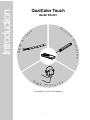
Introduction
QualColor Touch
D
M X
e s
r
F i x t u
Controlling a world of LED lighting
1
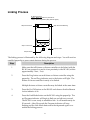
The Model RC-001 QualColor Touch handheld remote control provides unprecedented control
of color-capable lighting systems. Integrating an easy-to-use touch sensitive surface and
capable wireless interface, the RC-001 allows full control over a lighting system’s color and
intensity. The RC-001 can control all Giulio Lighting wireless fixtures and fixture controllers
using the LEDlink wireless interface.
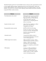
Feature
Benefit
Two dimensional color control
Selecting the exact color you want has
never been easier. Simply slide your
finger up and down to select the hue
and left and right to select the
saturation level. The lighting fixture
follows in real-time.
Separate intensity control
Adjust the fixture brightness without
affecting the selected color.
Completely off to full-on.
Programmable memory presets
Quickly recall a favorite setting.
Found a color that you love? Easily
store it for use later. Pleasantly fade
from the current setting to the
memory preset.
Automatic mode
Command the lighting system to
automatically fade between colors for
a never ending light show.
LEDlink digital radio interface
Makes installation a breeze. Works
without having to point the control at
a fixture. Allows one control to
simultaneously control multiple
fixtures in a completely synchronized
fashion.
USB interface
Connect to a Microsoft Windowsbased PC or Apple Macintosh to
configure advanced features in the
remote control or to allow computer
control of the lighting system.
2
Getting Started
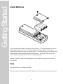
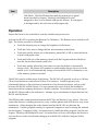
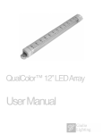
Install Batteries
Four AA batteries should be installed as shown above. Note that the battery cover is
held in place using a screw. Use Alkaline batteries for best results. A fresh set of
batteries should provide years of normal service. An indicator light on the front of the
remote blinks when the batteries should be replaced. The remote will not become
active when the batteries are too low for correct operation.
Batteries should be removed if the remote is to be stored for a period in excess of a
few months.
Care
Keep the RC-001 out of direct sunlight.
The front surface may be cleaned with a damp cloth. Do not use commercial cleaners.
3
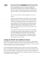
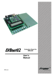
Control Description
1
2
3
4
M1
M2
AUTO
5
7
6
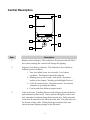
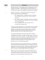
Item
Description
1
Remote Active indicator. This indicator is lit whenever the RC-001 is
active and touching the controls will change the lighting.
2
Program/Low Battery indicator. This indicator is lit or flashes to
indicate special conditions.
1. Very slow blink (every two seconds) : Low battery
condition. The batteries should be replaced.
2. Blinking (every one second) : Link mode. Described
further in the chapter “Working with Multiple Devices”.
3. Solid (lit continuously): Computer control. An external
computer is operating the remote.
4. One second flash: Memory preset stored.
3
Color touch area. Touching this area with a finger tip selects the hue
and saturation of the fixture. Hue is selected along the vertical axis
and saturation is selected along the horizontal axis. Fully saturated
colors may be selected on the left side of the area. The right side sets
the fixture to fully white. Sliding the finger around in this area
causes dynamic lighting changes in the fixture(s).
4
Item
Description
4
Intensity touch area. Touching this area with a finger tip selects the
intensity of the fixture. Touch the black dot at the left side to set
intensity to zero (off). Touch the right side to set the fixture intensity
to 100% (full on). Slide to dynamically change the fixture intensity.
5
Function touch buttons. Touching these areas with a finger tip
selects a function associated with the label.
1. M1 : Memory Preset 1. Transmits or stores a color (hue
and saturation) and intensity level. Factory default is
fixture off.
2. M2 : Memory Preset 2. Transmits or stores a second color
(hue and saturation) and intensity level. Factory default is
white at full brightness.
3. Auto : Automatic mode. Sets the fixture into an
automatically changing mode.
Touching and quickly releasing one of the memory presets transmits
a command to fade the fixture to the stored values. Touching and
holding one of the memory presets until the Program indicator
flashes on and then off stores the last combination of color and
intensity selected in the Color and Intensity touch areas.
Touching and releasing the Auto button transmits a command
switching the fixture into one of eight automatic modes. Only one is
assigned to the Auto button at a time. A utility program running on
a computer can be used to change the assignment. A fixture set into
an automatic mode will remain in that mode until the color or
intensity is manually changed by touching either the Color or
Intensity areas or one of the memory presets.
The default automatic mode, assigned at the factory, commands the
fixture to fade between randomly selected colors with each change
taking between 10 and 60 seconds. All fixtures will fade between the
same colors over the same periods (operate identically) when the
RC-001 is used to control multiple fixtures at the same time.
6
Remote On/Off. Switch the remote on by pressing this button in
order to make the touch sensitive controls active. The remote will
automatically switch off after 60 seconds of inactivity. Pressing this
button does not affect the operation of the fixture itself.
5
Item
Description
7
Link Mode. The Link Mode button puts the remote into a special
mode described in chapter “Working with Multiple Devices”
designed to allow it to be linked with specific fixtures. It is designed
to be depressed by the end of an unrolled paper-clip.
Operation
Ensure the fixture to be controlled is correctly installed and powered on.
Activate the RC-001 by pressing the Remote On/Off button. The Remote Active indicator will
light. The fixture can now be controlled.
• Touch the Intensity area to change the brightness of the fixture.
• Touch the Color area to change the hue and saturation of the fixture.
• Touch and quickly release one of the memory presets M1 or M2 to cause the fixture
to fade to the preset value.
• Touch and hold one of the memory presets until the Program indicator flashes to
store the last touched intensity and color.
• Touch and quickly release the Auto button to cause the fixture to dynamically
change colors. The fixture will continue to automatically change colors even if the
remote is off. It will automatically change colors until the Color or Intensity or one
of the memory presets is touched.
The RC-001 must be within range of the fixture. The RC-001 will typically work up to 100 feet
(30 m) from the fixture outdoors and 50 feet (15 m) indoors. Actual range may vary
substantially based on the position and orientation of the fixture and objects, such as walls,
between the RC-001 and the fixture. For best operation be sure to follow the installation
instructions that accompany the fixture or fixture controller. Do not hold or cover the top of
the RC-001 (the area above the indicators). Attempt to put a minimum of objects between the
RC-001 and the fixture.
The LEDlink radio communication between the RC-001 and fixtures is very robust. However
some other devices, including microwave ovens, cordless phones and Wifi devices, may cause
interference. Often changing the radio channel used by the RC-001 can alleviate the
interference. A utility program running on a personal computer is used to change the channel.
See the chapter “Computer Utility” for instructions to install the utility program. See the next
chapter “Working with Multiple Devices” for instructions on how to reconfigure the fixture to
also use the new radio channel after changing it in the RC-001 with the Computer Utility
program.
6
Working with Multiple Devices
Links
A RC-001 and one or more fixtures or fixture controllers communicate using the
proprietary LEDlink radio protocol sharing certain characteristics called a Link. A
RC-001 is considered linked to a fixture when it and the fixture share the same Link
characteristics. RC-001 remote controls may be linked to fixtures in a variety of ways.
1. One RC-001 to one light fixture or fixture controller. The basic
configuration. All devices come from the factory with a default set of Link
characteristics allowing the basic configuration to work immediately.
2. One RC-001 to multiple light fixtures. One RC-001 will control more than
one fixture or fixture controller identically if all share the same Link
characteristics (the factory default set for example).
3. More than one RC-001 devices controlling a single fixture or fixture
controller. Multiple RC-001 remote controls can control a single fixture (or
even a group of fixtures) if they all share the same Link characteristics.
4. Multiple RC-001 devices controlling multiple fixtures independently.
Particular RC-001 remote controls and light fixtures or light fixture
controllers can be linked to operate independently of other devices by
assigning different Link characteristics to them. For example, a set of under
cabinet fixtures may be controlled by one RC-001, while a set of cove
fixtures may be controlled by another RC-001 without interference between
the two pairs of devices.
The RC-001 has built-in capability to support up to three independent pairs of RC-001
and fixtures operating in close proximity. More sophisticated configurations or
changing certain Link characteristics require the use of a utility program running on a
personal computer connected to the RC-001 over a USB interface. Use of the utility
program is described in the next chapter, “Computer Utility”.
This chapter describes how to Link RC-001 remote controls to fixtures and fixture
controllers.
7
Link Overview
Links managed by the RC-001 remote control include the following attributes. These
attributes define the Link characteristics.
1. Radio channel : Specifies the common frequency the radio transmitter in the RC-001
and radio receiver in the fixture are tuned to.
2. Network ID : The Network ID is designed to allow multiple, overlapping pairs of
RC-001/fixtures to work without interference. A common use is to prevent a RC-001
in one apartment or home from affecting a light fixture in another apartment or
home.
3. Device address : Each fixture or fixture controller may be configured with a unique
device address. The RC-001 is configured with the device address for the fixture it
controls.
The factory default configuration for the RC-001 and all LEDlink capable Giulio Lighting
fixtures or fixture controllers contains the same linking attributes allowing a RC-001 remote
control to immediately work with these fixtures.
Certain conditions may require that one of the Link attributes be changed. Example
conditions include the following.
1. The user desires to have multiple RC-001 remote controls, each controlling a
separate fixture.
2. The user desires to change the Radio channel to avoid radio interference from a
microwave oven.
3. The user desires to change the Network ID to avoid interference from a lighting
system in another apartment or home.
The RC-001 contains a built-in mechanism for quickly changing the link to support up to 3
separately addressed fixtures without the use of a computer. This allows up to three separate
RC-001 remote controls to operate in the same environment independently controlling up to
three fixtures or sets of fixtures. This mechanism does not require the use of the utility
program and is described in this section.
For other changes, a utility program, described in chapter “Computer Utility”, is run on a
personal computer connected to the RC-001. The program allows the user to change the
desired Link attribute in the RC-001. Then the RC-001 is disconnected from the computer and
used to transfer the attributes to selected fixtures and fixture controllers by the linking process
described in this section. The linking process configures both the RC-001 and any fixture or
fixture controllers that it is linked to with the same Radio channel, Network ID and Device
address.
8
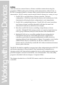
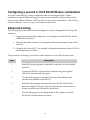
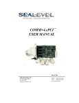
Linking Process
On Remote Device
Step 1: Make sure device is powered on.
Step 2: Press Prog Button (Prog indicator lights).
Step 3b: Ensure Lit
Step 4b: Ensure Blinking
"1"
"2"
"3"
Step 5: Touch one
Step 4a: Press
Step 3a: Press
The linking process is illustrated by the following diagram and steps. You will need an
unrolled paperclip to press certain buttons during the process.
Step
Description
1
Make sure that all fixtures or fixture controllers to be linked with the
RC-001 are powered on and in close proximity to the RC-001 (within
approximately 5 feet / 2 m).
2
Press the Prog button on each fixture or fixture controller using the
paperclip. The red Prog indicator next to the button will light. The
fixture or fixture controller is ready to be linked.
Multiple fixtures or fixture controller may be linked at the same time.
3
Press the On/Off button on the RC-001 and observe that the Remote
Active indicator is lit.
4
Press the Link Mode button on the RC-001 using the paperclip. The
red Program indicator will begin to flash on and off every second.
The RC-001 is now ready to establish a link. It will remain ready for
30 seconds. After 30 seconds the Program indicator will stop
flashing and the Link Mode button must be depressed again to reenable the linking process.
9
Step
Description
5
Touch one of the Function buttons to establish the specific link
between the RC-001 and any fixture or fixture controller that has
been enabled to be linked in step 2. The M1 button establishes a link
with Device address 1, the M2 button establishes a link with Device
address 2 and the Auto button establishes a link with Device address
3.
Note: The factory default for all Giulio Lighting devices is Device
address 1.
6
Observe that the Prog indicators on the fixture or fixture controllers
enabled in step 2 turns off. This indicates the link was successfully
established. If the Prog indicator does not turn off then the link was
not successfully established (the distance between RC-001 and the
fixture may have been too great, there was some radio interference
during the linking or the 30 second link period in RC-001 expired).
Attempt the linking again by touching the same Function touch
button as done before in step 5 (ensure the Program indicator on the
RC-001 is flashing).
7
Test the link once the fixture or fixture controllers have successfully
received the link information (their Prog indicators turn off). Either
wait for the Program indicator on the RC-001 to stop flashing or
press the Link Mode button on the RC-001 before the 30 second
period expires to restore normal operation. Changing the intensity
and color on the RC-001 should result in operation of all properly
linked fixtures or fixture controllers.
Linking the RC-001 with additional fixtures
Each RC-001 can control more than one fixture or fixture controller. As configured at the
factory, all Giulio LEDlink capable devices share the same Link characteristics. If the Link
attributes of the RC-001 have not been changed then additional fixtures or fixture controllers
will work immediately with no other actions required.
If a Link attribute has been changed or the new fixture is to work with a second or third
RC-001 (as described in the following pages) then the new fixture must be linked with the
RC-001 as described in the previous section. Be sure to use the same Device address as was
used for any previous linkings. For example, Device address 1 for factory default fixtures.
Device address 2 is used for second RC-001/fixture combinations and Device address 3 is used
for third RC-001/fixture combinations.
10
Configuring a second or third RC-001/fixture combination
A second or third RC-001/fixture combination that works independently of other
combinations may be linked following the procedure described in the preceding section.
Select Device Address 2 (Button “M2”) in step 5 for the second combination. Select Device
Address 3 (Button “Auto”) in step 5 for the third combination.
Advanced Linking
The utility program described in the next chapter is used for changing the following Link
attributes.
1. Supporting more than three addresses. For example if a fourth RC-001/fixture
combination is desired.
2. Adjusting the Radio channel. For example to eliminate interference from a Wifi
network.
3. Changing the Network ID. For example to eliminate interference from a RC-001 in
another apartment or home.
The procedure for changing one of these Link attributes involves the following steps.
Step
Description
1
Install the utility program on a personal computer if it is not already
installed.
2
Connect the RC-001 to the personal computer using the supplied
USB cable. Start the utility program.
3
Use the utility program to change the desired Link attribute and
store the new attribute in the RC-001.
4
Shut down the program and then disconnect the RC-001 from the
personal computer. Bring it within close proximity to any fixtures or
fixture controllers that it should be linked with.
5
Use the linking process described earlier in this chapter to (re)link
the RC-001 with the fixture or fixtures.
11
12
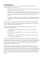
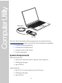
Computer Utility
USB Cable
RC-001
The Color Touch Commander utility program may be downloaded from the
www.giuliolighting.com website to provide the following additional capabilities.
1. Customize the linking attributes.
2. Customize the Function buttons.
3. Computer control of the fixtures.
4. Fixture configuration.
System Requirements
Microsoft Windows PC
• Windows XP with Service Pack 2, Windows Vista, Windows 7
• 25 MB spare disk space
• Spare USB Port
Apple Macintosh
• Mac OS X 10.5 or later running on an Intel Processor
• 25 MB spare disk space
• Spare USB Port
13
Installing Software
Please check the downloads section of the www.giuliolighting.com website for the most
current version of Color Touch Commander and to check compatibility with operating
systems not listed in the System Requirements.
Microsoft Windows PC
Download the zip file containing the Microsoft Windows PC version of the program to a
known location. Windows will give you the option of downloading it or opening it. You will
need to unzip the file if you download it before you can install the application. A folder will
open containing the QualColorTouch.exe installer program once the file has been downloaded
and unzipped.
Double-click the installer program to start the installation process. Follow the instructions
provided by the installer program to complete the installation.
Apple Macintosh
Download the dmg file containing the Apple Macintosh version of the program to a known
location such as the downloads folder. Open the dmg file by double-clicking on its icon or
selecting it from a stack (from the downloads folder icon on the dock for example).
Drag the Color Touch Command icon into the Applications folder. The application is installed.
Operation
To operate the software follow the instructions in the QualColor Touch Commander program
Installation Guide and User Manual that may be downloaded from the website.
Note: Do not connect the RC-001 to the computer until the software has been successfully
installed. Connecting the RC-001 to the computer before the software has been installed may
cause the operating system to prompt for an installation disk. Click the Cancel button if this
happens. All necessary software will be installed along with the program.
14
Specifications
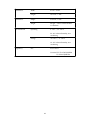
Functions
Color Selection
Hue and Saturation
Intensity Selection
0 - 100%
Memory Settings
2 non-volatile Hue/Saturation/
Intensity presets
1 non-volatile Auto mode preset
Automatic Functions
Pseudo-random color selection with
four selections for rate of change.
Sequential color selection with four
selections for rate of change.
Computer Interface
USB 2.0 Full speed compatible.
Computer configuration of RC-001.
Computer control of lighting system.
Touch Surface
Radio
Sensor Type
Capacitive
Hue Range
1026 counts
Saturation Range
256 counts
Intensity Range
256 counts
Type
Giulio Lighting LEDlink proprietary
digital bi-directional protocol.
Interoperates with all Giulio
Lighting LEDlink capable fixtures
and fixture controllers.
Modulation Type
GFSK
Frequency Range
2.4 GHz Instrument, Scientific and
Medical band (ISM)
2.402 GHz - 2.480 GHz
Power
Power Output
0 dBm max at antenna input
Battery
6 volt (4 x AA), 30 mA max
USB
5 volt, 55 mA max
15
Dimensions
Dimensions
Environmental
Width
6.5 cm / 2.559”
Length
18.15 cm / 7.146”
Height
2.639 cm / 1.039”
Weight
225 gm / 7.94 Oz with 4 Alkaline
AA batteries
Operating
0 - 50º C / 32 - 122º F
20 - 90% relative humidity, noncondensing
Storage
-20 - 60º C / -4 - 140º F
10 - 95% relative humidity, noncondensing
Regulatory
FCC
FCC Class B
Contains FCC ID: XO6-DJ2MOD1
IC: 8558A-DJ2MOD1
16
Warranty Information
Manufacturer warrants this product to be free from defects in material and
workmanship under normal use and conditions ("manufacturing defect") for a
period of one (1) year from date of original purchase (the invoice date). This
warranty extends to the original buyer (Purchaser) or end-user customer of
Manufacturer authorized reseller, and does not apply to fuses, batteries, equipment
attached to product or any product, which, in Manufacturer's opinion, has been
misused, altered, neglected or damaged by accident or abnormal conditions of
operation or handling. Manufacturer will, at its option, repair or replace the
Product, or reimburse Purchaser or end user for the full purchase price.
To obtain service, obtain a return authorization (RMA) from the Manufacturer website
and then follow the instructions for return of the unit you receive with the RMA.
THIS WARRANTY IS PURCHASER’S SOLE AND EXCLUSIVE REMEDY AND IN IS
IN LIEU OF ALL OTHER WARRANTIES, EXPRESSED OR IMPLIED, INCLUDING,
BUT NOT LIMITED TO, ANY IMPLIED WARRANTY OF MERCHANTABILITY OR
FITNESS FOR A PARTICULAR PURPOSE. MANUFACTURER SHALL NOT BE
LIABLE FOR ANY SPECIAL, INDIRECT, INCIDENTAL OR CONSEQUENTIAL
DAMAGES OR LOSSES, INCLUDING LOSS OF DATA, WHETHER ARISING FROM
BREACH OF WARRANTY OR BASED ON CONTRACT, TORT, RELIANCE OR ANY
OTHER THEORY.
Since some countries and states do not allow limitation of the term of an implied
warranty, or exclusion or limitation of incidental or consequential damages, the
limitations and exclusions of this warranty may not apply to every buyer. If any
provision of this warranty is held invalid or unenforceable by a court of competent
jurisdiction, such holding will not affect the validity or enforceability of any other
provision of this warranty.
17
This device complies with Part 15 of the FCC Rules. Operation is subject to the
following two conditions: (1) This device may not cause harmful interference, and (2)
This device must accept any interference received, including interference that may
cause undesired operation.
This equipment has been tested and found to comply with the limits for Class B
Digital Device, pursuant to Part 15 of the FCC Rules. These limits are designed to
provide reasonable protection against harmful interference in a residential installation.
This equipment generates and can radiate radio frequency energy and, if not installed
and used in accordance with the instructions, may cause harmful interference to radio
communications. However, there is no guarantee that interference will not occur in a
particular installation. If this equipment does cause harmful interference to radio or
television reception, which can be determined by turning the equipment off and on,
the user is encouraged to try to correct the interference by one or more of the
following measures.
• Reorient or relocate the receiving antenna
• Increase the separation between the equipment and receiver
• Connect the equipment into an outlet on a circuit different from that to which the
receiver is connected
• Consult the dealer or an experienced radio/TV technician for help
Any changes or modifications not expressly approved by the party responsible for
compliance could void the user’s authority to operate the equipment.
18
FCC Statement
INFORMATION TO USER
Copyright © 2010 Giulio Lighting
All rights reserved
Neither the whole nor any part of the
information contained in, or the product
described in this manual, may be adapted or
reproduced in any material or electronic form
without the prior consent of the copyright
holder.
QualColor is a trademark of Giulio Lighting.
All other brand or product names are
trademarks or registered trademarks of their
respective owners.
Contact
www.giuliolighting.com
[email protected]
This document and the functionality of the
product may be subject to change without
notice.
Publication 24-00012-01
19