1
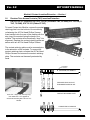
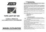
Downloadable Documents (Adobe Acrobat (TM) format) Click on the links below to view or download copies of VPC User Manual in Adobe Acrobat (.PDF) format. Note: If you would like printed copies of any of these documents, please send a message with your name, address and daytime telephone number to Requests. Section 1 Need the reader? Click here! Module & Contact Installation/Removal Instructions 1.0 Receiver TAC Contact Insertion/Extraction 2.0 TAC (Receiver) Module Installation/Removal 3.0 Wiring Contact Insertion/Extraction 4.0 Receiver Wiring Module Installation/Removal 5.0 ID Wiring Module Installation/Removal 6.0 Blank Module Installation/Removal 7.0 Exploded View of MITT Interface System Components Section 2 Engagement of ID with Receiver Section 3 Care & Maintenance (System Precautions & TAC Contact Cleaning) Section 4 Contact Assembly Instructions VPC P/Ns Description Type Cable 610127110 Signal Wiring Contact, RCVR/ID, Crimp/Solder 610134101 Coaxial Wiring Contact, RCVR/ID, Solder Sleeve RG316 610134101 Coaxial Wiring Contact, RCVR/ID, Solder Sleeve RG178 20 AWG max Section 5 PWB Assembly/Recommendations 1.0 Assembly of PWB to Receiver or ID 2.0 Pad Recommendations for PWB Development Note: Please be advised that all drawings within each section are not to scale. Ver. 2.0 MIT USERS MANUAL Module & Contact Insertion/Extraction Section 1 1.0 Receiver Twin Access Contacts (TAC) Insertion/Extraction P/N 610 122 101 (Signal/S-TAC), 610 133 101 (Coaxial/C-TAC, 50 OHM), 610 133 102 (CTAC, 75 OHM), 610 135 101 (Power/P-TAC) To insert Contact into Module, remove the contact retaining plate from the bottom of the module by unfastening the #2 Flat Head Phillips Screws. Insert contacts into the rear of the module with the stop ring of the contact facing the back of the module. The contacts will automatically drop into alignment. Replace the contact retaining plate and secure with two #2 Flat Head Phillips Screws. The contact retaining plate must be removed prior to the extraction of the contacts. To remove the contact retaining plate, unfasten the #2 Flat Head Phillips Screws and remove the contact retaining plate. The contacts are then easily extracted by hand. TAC Module shown with Retaining Cap removed to allow for the insertion of TAC Contacts (RECEIVER) TAC MODULE STOP RING OF PIN ALWAYS TOWARD RETAINING PLATE Insert TACs longer end (from stop ring) into module first. Once populated, refasten the Retaining Plate onto the TAC Module. CONTACT RETAINING PLATE COMPLETED TAC MODULE Virginia Panel Corporation 3 MIT USERS MANUAL Ver. 2.0 Module & Contact Insertion/Extraction Section 1 2.0 TAC (Receiver) Module Installation/Removal P/N 510 130 117 (380 pos. Signal Module), 510 130 121 (220/24 pos. Signal/Coaxial Module)510 130 173 (46 pos. Coaxial or Power Module), 510 130 180 (180/10 pos. Signal/ Coaxial 75 OHM Module) To install a module into the Receiver, place two, #2 Socket Head Cap Screws, .50" in length, in the TAC Receiver Module. Place the Module in the front of the Receiver aligning the locating pins on the module with the appropriate holes in the Receiver Frame, so that the upper and lower module screws touch the mating holes the Receiver Frame (install modules such that the numbers can be read from top to bottom, making them right side up). Using a 5/64 Allen Hex Wrench, tighten the top screw 1 to 2 full revolutions, while lightly applying pressure against the face of the module. Maintain this pressure while tightening the bottom screw 1 to 2 full revolutions. Repeat this sequence, in order, until the module is seated. As the module is being seated, watch to ensure that it does not become cocked at any time as a result of the guide pins not being properly aligned with the receiver or binding of the pins due to one screw being advanced ahead of the other more than 1 to 2 turns. If this should occur, back the screws off until the module is level, and repeat the tightening process. Torque the screw until it is 4 to 5 inch pounds Place the Protective Module Cover on the front of the Receiver with the counter-sunk holes facing upward and verify alignment of the clearance holes with the contacts in the TAC Receiver Module. Using the #2 Flat Head Phillips screws, secure the cap in place until screws are firmly seated. Prior to Module removal, the Protective Module Cover must be removed. To remove, unfasten the two #2 Flat Head Phillips screws and remove the cover. PROTECTIVE MODULE COVER ATTACHES TO FACE OF RECEIVER INSERT TAC MODULE SUCH THAT THE RETAINING PLATE FACES BACK OF RECEIVER SCREENED SIDE UP 4 TAC Module (P/N 510 130 121 shown) in place screened side up. Protective Module Cover has not been secured to the face of the Receiver. P/N: VMMIT100 Ver. 2.0 MIT USERS MANUAL Module & Contact Insertion/Extraction Section 1 3.0 Wiring Contact Insertion/Extraction P/N 610 127 110 (Signal Crimp/Solder Contact), 610 127 111 (Signal Wire-Wrap Contact), 610 134 101/102/103/104/105 (Coaxial Contacts), 610 136 101/102 (Power Contacts) To insert Contact into Module, first terminate contact by crimping, soldering, wire-wrapping (see termination instructions in Section 4) or using SMB/SSMB connectors. Insert terminal into module until top of contact is flush with module. When installing Wiring Contacts in the Receiver Wiring Module (P/N 510 130 161, 510 130 162, 510 130 174, 510 130 181), insert the contacts in from the screened side of the module. When installing Wiring Contacts in the ID Wiring Module (P/N 510 131 138, 510 131 139, 510 131 144, 510 131 145), insert the contacts from the screened side of the module as well. To remove the Wiring Contacts, place the appropriate Extraction Tool (Signal - P/N 910 110 110, Coaxial/Power - P/N 910 112 112, Coaxial/75 OHM - 910 112 116), over the contact into the counter bore on the mating side of the module. Press into the contact until the retaining ring is released and contact begins to emerge from the rear of the module. Remove the contact by hand. Insertion ID WIRING MODULE SHOWN Extraction ID WIRING MODULE SHOWN CAUTION TWIST POWER/COAXIAL AND SIGNAL EXTRACTION TOOLS SLIGHTLY TO ENSURE THAT RETAINING CLIP EARS HAVE FULLY COLLAPSED BEFORE APPLYING PRESSURE TO HANDLE TO AVOID DAMAGE TO CONTACTS, ALWAYS ENSURE THAT TOOL IS PERPENDICULAR TO MODULE FACE Virginia Panel Corporation 5 MIT USERS MANUAL Ver. 2.0 Module & Contact Insertion/Extraction Section 1 4.0 Receiver Wiring Module Installation/Removal P/N 510 130 161 (380 pos. Signal Module), 510 130 162 (220/24 pos. Signal/Coaxial Module) 510 130 174 (46 pos. Power or Coaxial Module), 510 130 181 (180/10 pos. Signal/ Coaxial 75 OHM Module) Place the module on the rear of the Receiver aligning the locating pins on the modules with the appropriate holes in the Receiver Frame. Install the modules such that the numbers can be read from top to bottom, making them right side up. Insert the #2 Socket Head Cap Screws, .50" length, in the module fastening holes. Using a 5/64 Allen Hex Wrench, tighten the top screw 1 to 2 full revolutions, while lightly applying pressure against the face of the module. Maintain this pressure while tightening the bottom screw 1 to 2 full revolutions. Repeat this sequence until the module is seated. Torque the screw until it is 4 to 5 inch pounds. To remove, loosen the top screw 1 to 2 full revolutions. Loosen bottom screw 1 to 2 full revolutions. Repeat this sequence until the module is separated from the Receiver. SCREENED SIDE OF MODULE (NOTE: IT IS IMPORTANT TO ALTERNATE THE TIGHTENING/LOOSENING OF MODULE SCREWS) Back-side of Receiver with Receiver Wiring Module (P/N 510 130 162) shown 6 P/N: VMMIT100 Ver. 2.0 MIT USERS MANUAL Module & Contact Insertion/Extraction Section 1 5.0 Interface Device (ID) Wiring Module Installation/Removal P/N 510 131 138 (380 pos. Signal Module), 510 131 139 (220/24 pos. Signal/Coaxial Module) 510 131 144 (46 pos. Power or Coaxial Module), 510 131 145 (180/10 pos. Signal/Coaxial 75 OHM Module) To install Module into ID, place module in the ID with the screening facing downward. Align top of the module with the designated top of the ID and the locating pins on the module with the appropriate holes in the ID. The modules should be installed such that the numbers can be read from top to bottom. Insert the #2 Socket Head Cap Screws, .50" length, in the module fastening holes. Using a 5/64 Allen Hex Wrench, tighten the top screw 1 to 2 full revolutions, while pushing lightly against the face of the module. Maintain this pressure while tightening the bottom screw 1 to 2 full revolutions. Repeat this sequence until the module is seated. Torque the screw until it is 4 to 5 inch pounds. SCREENED SIDE OF MODULE To remove, loosen the screws until the module is separated from the ID. 6.0 Blank Module (Receiver/ID) Installation/Removal P/N 510 130 123, 510 131 113 The Blank Module is used in the Receiver or ID when module spaces are not in use. Place the Blank Module in the respective Receiver/ID. Insert #2 Screws in the module fastening holes and tighten. To remove, loosen the screws until the module is separated from the Receiver/ID. Virginia Panel Corporation 7 Ver. 2.0 MIT USERS MANUAL Module & Contact Insertion/Extraction Section 1 5.0 Interface Device (ID) Wiring Module Installation/Removal P/N 510 131 138 (380 pos. Signal Module), 510 131 139 (220/24 pos. Signal/Coaxial Module) 510 131 144 (46 pos. Power or Coaxial Module), 510 131 145 (180/10 pos. Signal/Coaxial 75 OHM Module) To install Module into ID, place module in the ID with the screening facing downward. Align top of the module with the designated top of the ID and the locating pins on the module with the appropriate holes in the ID. The modules should be installed such that the numbers can be read from top to bottom. Insert the #2 Socket Head Cap Screws, .50" length, in the module fastening holes. Using a 5/64 Allen Hex Wrench, tighten the top screw 1 to 2 full revolutions, while pushing lightly against the face of the module. Maintain this pressure while tightening the bottom screw 1 to 2 full revolutions. Repeat this sequence until the module is seated. Torque the screw until it is 4 to 5 inch pounds. SCREENED SIDE OF MODULE To remove, loosen the screws until the module is separated from the ID. 6.0 Blank Module (Receiver/ID) Installation/Removal P/N 510 130 123, 510 131 113 The Blank Module is used in the Receiver or ID when module spaces are not in use. Place the Blank Module in the respective Receiver/ID. Insert #2 Screws in the module fastening holes and tighten. To remove, loosen the screws until the module is separated from the Receiver/ID. Virginia Panel Corporation 7 MIT USERS MANUAL Ver. 2.0 Module & Contact Insertion/Extraction Section 1 7.0 Exploded View of MIT Interface System Components TAC MODULE P/N 510 130 117 510 130 121 (SHOWN) 510 130 173 510 130 180 DESCRIPTION 380 POS SIGNAL 220/24 POS SIG/PWR OR CX 46 POS PWR OR CX 180/10 POS SIG/CX (75 OHM) RECEIVER P/N 310 117 128/ 310 117 120 OR 310 117 129/ 310 117 121/ 310 117 122 DESCRIPTION MICRO INTERFACE TECHNOLOGY (MIT) RECEIVER, 2 MODULE POSITIONS MICRO INTERFACE TECHNOLOGY (MIT) RECEIVER, 4 MODULE POSITIONS RECEIVER WIRING MODULES P/N DESCRIPTION 510 130 161 380 POS SIGNAL 510 130 162 220/24 POS SIG/PWR OR CX (SHOWN) 510 130 174 46 POS PWR OR CX 510 130 181 180/10 POS SIG/CX (75 OHM) INTERFACE DEVICE (ID) P/N DESCRIPTION 410 115 113 MICRO INTERFACE TECHNOLOGY (MIT) INTERFACE DEVICE (ID), 2 MODULE POSITIONS 410 115 114 MICRO INTERFACE TECHNOLOGY (MIT) INTERFACE DEVICE (ID), 4 MODULE POSITIONS 8 ID WIRING MODULES P/N DESCRIPTION 510 131 138 380 POS SIGNAL 510 131 139 220/24 POS SIG/PWR OR CX (SHOWN) 510 131 144 46 POS PWR OR CX 510 131 145 180/10 POS SIG/CX (75 OHM) P/N: VMMIT100 Ver. 2.0 MIT USERS MANUAL Engagement of ID with Receiver Section 2 ! Caution ! When engaging the ID with the Receiver, caution must be taken to ensure that the ID is parallel with the Receiver upon engagement and that the Receiver bayonet fittings are engaged simultaneously. All power supplies for the system should be properly disconnected prior to handling. Caution should always be used during engagement, making sure that all foreign objects are removed from the system. Serious damage can be caused to the TAC contacts if they are not protected when the system is disengaged. It is recommended that either the ID or Receiver Protective Cover is engaged to the Receiver at all times. Listed below are the required steps to be taken prior to the engagement of the ID and Receiver. Prior to engaging an ID with the Receiver for the first time, the user may find it to be good practice to check that all the Modules (ID and Receiver) have been installed prop erly. This would involve the inspection of the module ends - ensuring the even height of all module ends relative to one-another. While checking this, the user should verify the positioning of the modules themselves. The top of each module is marked with a T. It is crucial for all modules to be installed properly. Improper installation will cause damage to the Modules, and possibly to the ID and/or Receiver. All ID Modules have to match the Receiver Modules. This means that upon engage ment, an ID Module will mate with its respective Receiver Module (Signal ID to mate with Signal Receiver, etc.) The handle may now be rotated to the open position. Remove the Receivers Protective Cover by sliding it up and pulling it away from the Receiver. The ID, upon being inspected, is now ready for engagement with the Receiver. The Receiver should be checked one last time for any foreign objects that may hinder the engagement. To attach the ID to the Receiver, place ID over captive fittings, applying pressure to the ID towards the front of the Receiver and slide down until the top of the ID is flush with the top of the Re ceiver. The handle may then be rotated to the closed position. Always protect the contacts when the system is not in use. The contacts are protected when either the ID or the Receiver Protective Cover is engaged to the Receiver. Upon complet ing use of ID, rotate the receiver handle to the open position, remove the ID, reinstall the protect ive cover and rotate the handle to the closed position. It is recommended that all module positions of the MIT are filled with configured modules. This will prevent any uneven engagement of the MIT Receiver mechanism. Virginia Panel Corporation 9 MIT USERS MANUAL Ver. 2.0 Care and Maintenance Section 3 1.0 System Precautions In the event of complications, such as improper alignment of Modules or the ID, a trained technician should be notified immediately to avoid any damage to the system. This should also apply to any difficulties that my be experienced during the engagement. The MIT is designed to be maintenance free. However, there are a few precautions to take in order to prolong the life of the system. ! Caution ! Serious damage can be caused to the TAC contacts if they are not protected when the system is disengaged. It is recommended that either the ID or Receiver Protective Cover is engaged to the Receiver at all times. 2.0 TAC Contact Cleaning Procedures TAC Contacts may require periodic cleaning during the life of the product due to the usage cycle imposed, as well as the environmental conditions to which it is subjected. If unacceptable resistance readings occur, the contacts should be cleaned using the following procedure: Spray contacts with filtered air or inert gas to remove any loose particle contamination. Clean contact mating surfaces using isopropyl alcohol and a soft bristle brush. (Do not pour alcohol directly onto contacts, apply to brush). Respray contacts with filtered air or inert gas to dry alcohol and remove any residual lint, dust, etc... By following this procedure for both the TAC contacts and the mating surface contacts or PCB pads, the user will avoid any performance problems that could arise due to contamination. 10 P/N: VMMIT100 MIT USER’S MANUAL Ver. 2.0 Contact Assembly Instructions — Section 4 Signal Terminal AssemblyP/N 610 127 110 Set up crimp tool P/N 910 101 103 (Fig. A) by loosening the latch locking screw (counter-clockwise, until turning stops). Remove any previously used crimp contact locator. Insert the open end of crimp contact locator P/N 910 104 133 into crimp tool contact locator retainer. Slide the retaining latch toward contact locator until contact is securely locked into place. The contact locator may have to be twisted to allow latch to retain contact locator. Tighten latch locking screw. Using the table below, adjust the crimp tool setting by pulling adjusting knob and turning it at the same time (clockwise increases, counter-clockwise decreases setting) until the desired setting is achieved on the microcrimp indicator. Wire Gauge 20 22 24 26 2-24 2-26 Strip Length +.05/-0.0 .25 .19 .19 .19 .25 .25 Fig. A Crimp Max. Crimp Min. .037 .033 .033 .029 .029 .025 .024 .021 .043 .041 .041 .037 Pullout Force (lb.) 10 10 8 4 8 4 Using the table above, determine the strip length according to wire gauge. Strip wire. Fully insert stripped wire into contact P/N 610 127 110 (Fig. B). With the crimp tool in the open position, insert the prepared contact and wire through the indenter opening. While keeping the wire fully inserted into the contact, squeeze the handles of the crimp tool until a positive stop is reached. Tool will release and return into fully “open” position. Remove crimped contact and wire. .047 DIA. .70 .065 DIA. Fig. B NOTE: Observe precision ratchet action by opening and closing tool fully several times. Note that tool cannot be opened without completing cycle. Never attempt to disassemble tool.Never tighten or loosen stop nuts on back of tool. 12 P/N: VMMIT100 Ver. 2.0 MIT USER’S MANUAL Contact Assembly Instructions — Section 4 Coaxial Terminal Assembly P/N 610 134 101 — RG316 PARTS REQUIRED: •Solder Kit for TAC includes holding fixture and adapter (P/N 910 121 162) or Adapter (for those who already own a holding fixture) (P/N 910 121 163) •Steinel Heat Gun with Reflector (P/N 910 121 160) INSTRUCTIONS: 1. Prepare the coaxial cable to the dimensions shown (Fig. A). 2. Straighten the center conductor making sure the stranded center conductor is twisted into its original lay. 3. Pretin stranded center conductor with Sn63 solder per QQ-S-571. Use RMA flux per MIL-F-14256 (Alpha #611 or equivalent). 4. Make sure the shield braid is trimmed evenly and no loose strands are extending out across the exposed dielectric or cable jacket. 5. Smooth the braid ends flat against the cable dielectric. Fig.A 6. Slip the contact over the end of the prepared cable, and carefully push the contact onto the cable until it stops. Rotating the contact slightly during cable insertion will help prevent the braid from catching. 7. Inspect for proper insertion (Fig. B). The center conductor must be visible through one of the forward inspection windows. The distance from the rear of the contact outer body to the cable jacket insulation should be .065±.015 8. Install the adapter onto the holding fixture (Fig. C). Insert a contact in the adapter and set up the dimensions as shown in Figure C. 9. Insert the contact/cable assembly into the adapter. Clamp the cable in the holding fixture. The cable must remain fully inserted in the contact and the contact must be fully inserted in the adapter (for the adapter to act as a heat sink). The cable must be straight between the contact and the cable clamp. Fig. B 10. Attach the appropriate reflector to the heating tool (see separate Heat Gun instruction sheet included with tool for tool operation and precaution). 11. Using the holding fixture, position the contact in the heating tool reflector, with the forward inspection window centered in the reflector. Continue heating until the small solder preform in the forward inspection window has melted and flowed. The large solder preform in the rear inspection window should have melted and flowed by this time; if it has not, direct hot air at the rear inspection window until it does. 12. If contact is UNDERHEATED, there will be visible remnants of the original shapes of the solder preforms. An underheated contact must be reheated. If contact is OVERHEATED, solder will wick away from the joint areas, leaving no solder fillets. An overheated contact must be removed and a new contact installed. 13. After the contact has cooled for at least 10 seconds, remove the contact and cable from the holding fixture. 14. Inspect the completed termination for correct assembly. The cable shield must extend into the contact at least as far as the front edge of the rear nspection windows. The center conductor must be visible through one of the forward inspection windows. Fig.C Virginia Panel Corporation revised 3/13/02 13 MIT USER’S MANUAL Ver. 2.0 Contact Assembly Instructions — Section 4 Coaxial Terminal Assembly P/N 610 134 101 — RG178 PARTS REQUIRED: •Solder Kit for TAC includes holding fixture and adapter (P/N 910 121 162) or Adapter (for those who already own a holding fixture) (P/N 910 121 163) •Steinel Heat Gun with Reflector (P/N 910 121 160) INSTRUCTIONS: 1. Prepare the coaxial cable to the dimensions shown (Fig. A). 2. Straighten the center conductor making sure the stranded center conductor is twisted into its original lay. 3. Pretin stranded center conductor with Sn63 solder per QQ-S-571. Use RMA flux per MIL-F-14256 (Alpha #611 or equivalent). 4. Fold the center conductor back on itself as shown (Fig. B). 5. Make sure the shield braid is trimmed evenly and no loose strands are extending out across the exposed dielectric or cable jacket. 6. Smooth the braid ends flat against the cable jacket. Fig. A 7. Slip the contact over the end of the prepared cable, and carefully push the contact onto the cable until it stops. Rotating the contact slightly during cable insertion will help prevent the braid from catching. 8. Inspect for proper insertion (Fig. C). The center conductor must be visible through one of the forward inspection windows. The distance from the rear of the contact outer body to the cable jacket insulation should be .015±.015. Fig. B 9. Install the adapter onto the holding fixture (Fig. D). Insert a contact in the adapter and set up the dimensions as shown in Figure D. 10. Insert the contact/cable assembly into the adapter. Clamp the cable in the holding fixture. The cable must remain fully inserted in the contact and the contact must be fully inserted in the adapter (for the adapter to act as a heat sink). The cable must be straight between the contact and the cable clamp. 11. Attach the appropriate reflector to the heating tool (see separate Heat Gun instruction sheet included with tool for tool operation Fig. C and precaution). 12. Using the holding fixture, position the contact in the heating tool reflector, with the forward inspection window centered in the reflector. Continue heating until the small solder preform in the forward inspection window has melted and flowed. The large solder preform in the rear inspection window should have melted and flowed by this time; if it has not, direct hot air at the rear inspection window until it does. 13. If contact is UNDERHEATED, there will be visible remnants of the original shapes of the solder preforms. An underheated contact must be reheated. If contact is OVERHEATED, solder will wick away from the joint areas, leaving no solder fillets. An overheated contact must be removed and a new contact installed. 14. After the contact has cooled for at least 10 seconds, remove the contact and cable from the holding fixture. 15. Inspect the completed termination for correct assembly. The cable shield Fig. D must extend into the contact at least as far as the front edge of the rear inspection windows. The center conductor must be visible through one of the forward inspection windows. revised 3/13/02 14 P/N: VMMIT100 Ver. 2.0 MIT USERS MANUAL PWB Assembly/Pad Recommendations Section 5 1.0 Assembly of PWB to Receiver/ID There are three options for mounting a PWB to the back-side of the MIT a PWB that covers both TAC Module positions, a PWB for either left or right TAC Module position, or two PWBs (one for left TAC Module position and one for the right TAC Module position). The mounting holes for the PWBs are indicated below. Caution needs to be taken when mounting the MIT to another surface while using a PWB. The mounting holes that are used for attaching the PWB(s) also need to be used to attach the Receiver to a chassis or mounting arms. Use spacers if only half of the Receivers back-side is occupied by a PWB so that the Receiver will mount to a flat surface properly. When mounting a Backplane or PWB thicker than 1/8", the flatness of the Backplane or PWB needs to be less than .010". Virginia Panel Corporation 15 MIT USERS MANUAL Ver. 2.0 PWB Assembly/Pad Recommendations Section 5 2.0 Pad Recommendations for PWB Development All contact pads are to be gold plated per MIL-G-45204, Type 1, Grade C, .000120 Min. thick over Nickel plating per QQ-N-290, Class 2, .000150 Min. thick. Board material is left to the user as the material used will depend upon vari ables such as anticipated environmental conditions (temperature, humidity, chemical resistance, etc.) and electrical parameters (voltage breakdown, dielec tric constant and others). Specific circuitry may also limit the desired flexing. VPC supplies the force per contact exerted upon the board and the contact array dimensions. Once the operational contact array is determined, we recommend that the complete environmental, electrical and mechanical requirements be given to a professional board de signer for design review. Contact Forces Signal TAC Contact Coaxial TAC Contact (50 OHM) Coaxial TAC Contact (75 OHM) Power TAC Contact 2 ounces maximum 7 ounces maximum 7 ounces maximum 20 ounces maximum Deflection at no time should exceed .020 16 P/N: VMMIT100