1
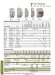
DIGITAL TIME RELAYS
SM / MCB / SER / ERTC / SSR / DG Series
(Er, R, Ts, Ta, Es, Em, Ef)
new
Er R
Ts
Ta
Es
Ef Em
MCB-9
MCB-20
Multi-function T. Relay
1sec - 100h
SM-9
Time Relay
0,1sec - 30 h
MCB-7
Time Relay
0,1sec - 60 h
MCB-8
Time Relay
0,1sec - 30 h
MCB-9
Time Relay
0,1sec - 30 h
MCB-30
Time Relay
2-30sec
MCB-60
Time Relay
4-60sec
Y
Y
SER-YU
24-240 VAC / DC
12-240 VAC / DC
220 VAC
24 VAC / DC
Trigger Input
(Ef)
Symmetric Flasher
Single shot trailling
edge with control input (Ta)
Single shot leading
(Em-2)
edge voltage controlled
(Es)
ON Delay with
Control Input
Single shot leading edge
(Ts)
with control input
(R)
OFF Delay with
Control Input
No Voltage,
Delayed Impulse
Left-Right
Star-Delta
Down-timer
OFF Flasher
ON Flasher
(Em-1)
Y
ERTC-01
OFF Delay
Product Code
(Er)
SER-Y/U
ON Delay
ERTC-01
/ U Relay 20-500msec. ( /U) 60sec ( )
SSR-2X
Left-Right Relay
1sec - 60 h
DG-06
Time Relay
0,1 - 6sec
MCB-15
Multi-function T. Relay
1sec-100 h
MCB-20
Multi-function T. Relay
0,05sec-100 h
SER-Y/U
DG-06
ERTC-01
SSR-2X
MCB-60
MCB-30
(new)
MCB-20
(new)
MCB-15
MCB-9
MCB-8
SPECIFICATIONS
MCB-7
MODELS
< 8 VA
< 3 VA
Electrical Parameters
Operating Voltage (Un)
230 V AC & 24 V AC / DC
pls.refer to
table above
Operating Range
230 V AC &
24 V AC / DC
230 V AC
Un±20% (for AC) ; In±10% (for DC)
Network Type
Single - phase / 2 wires
Power Consumption
< 8 VA
< 4 VA
Repetition Error
±0.1%
±5 msec.
Reset Time
Connection Type
150 msec.
=100 msec.
A (Terminal)
< 8 VA
200 msec.
1 C/O; 8 A, 2000 VA, cosj=1
Output Contact
< 3 VA
±0.1%
100 msec.
80 msec.
C
(Terminal)
2 C/O;
8A,2000VA,
cosj=1
1 C/O;
8A,2000VA,
cosj=1
-
120 msec.
E
2 NO;
5A,1250VA
A
1 C/O;
8A,2000VA
Mechanical Parameters
Degree of Protection
IP20
IP40
IP20
Dimensions
Weight / each
PK22
0,1 kg
PK27
0,1 kg
PK22
0,1 kg
Quantity in 1 package
24 pcs
10 pcs
24 pcs
IP20
IP40 (front panel)
PK15
PK20
0,3 kg
PK25
0,1 kg
PK10
0,25 kg
16 pcs
24 pcs
10 pcs
36
www.entes.com.tr
DIGITAL TIME RELAYS
SM / MCB / SER / ERT / SSR / MT-ST Series
Functions of MCB-15 and MCB-20
ON Delay (Er) [MCB-15 & MCB-20] :
When the supply voltage U is applied, the set interval t begins (green LED U/t flashes). After the interval
t has expired (green LED U/t illuminated) the output relay R switches into on-position (yellow LED
illuminated). This status remains until the supply voltage is interrupted. If the supply voltage is interrupted
before the expiry of the interval t, the interval already expired is erased and restarted when the supply
voltage is next applied.
Er
OFF Delay with control input (R) [MCB-15 & MCB-20] :
The supply voltage U must be constantly applied to the device (green LED U/t illuminated). When the
control contact S is closed, the output relay R switches into on-position (yellow LED illuminated). If the
control contact is opened, the set interval t begins (green LED flashes). After the interval t has expired
(green LED U/t illuminated) the output relay switches into off-position (yellow LED not illuminated).
If the control contact is closed again before the interval t has expired, the interval already expired is
erased and restarted at the the next opening of control contact S.
R
Single shot leading edge with control input (Ts) [MCB-20] :
The supply voltage U must be constantly applied to the device (green LED U/t illuminated). When the
control contact S is closed, the output relay R switches into on-position (green LED U/t illuminated) and
the set interval t begins (green LED U/t flashes). After the interval t has expired (green LED U/t
illuminated) the output relay switches into off-position (yellow LED not illuminated). During the interval,
the control contact can be operated any number of times. A further cycle can only be started when the
cycle run has been completed.
Ts
Single shot trailling edge with control input (Ta) [MCB-20] :
The supply voltage U must be constantly applied to the device (green LED U/t illuminated). Closing the
control contact S has no influence on the condition of the output R. When the control contact is opened,
the output relay switches into on-position (yellow LED illuminated) and the set interval t begins (green
LED U/t flashes). After the interval t has expired (green LED U/t illuminated), the ouput relay switches
into off-position (yellow LED not illuminated). During the interval, the control contact can be operated
any number of times. A further cycle can only be started when the cycle run has been completed.
Ta
ON delay with control input (Es) [MCB-20] :
The supply voltage U must be constantly applied to the device (green LED U/t illuminated). When the
control contact S is closed, the set interval t begins (green LED U/t flashes). After the interval t has
expired (green LED U/t illuminated) the output relay R switches into on-position (yellow LED illuminated).
This status remains until the control contact is opened again. If the control contact is opened before the
interval t has expired , the interval already expired is erased and restarted with the next cycle.
Single shot leading edge voltage controlled (Em-2) [MCB-15 & MCB-20] :
When the supply voltage U is applied, the output relay R switches into on-position (yellow LED illuminated)
and the set interval t begins (green LED U/t flashes). After the interval t has expired (green LED U/t
illuminated) the output relay switches into off-position (yellow LED not illuminated). This status remains
until the supply voltage is interrupted. If the supply voltage is interrupted before the interval t has expired,
the output relay switches into off-position immediately. The interval already expired is erased and restarted
when the supply voltage is next applied.
Em-2
Flash (Ef) [MCB-15 & MCB-20] :
When the supply voltage U is applied, the set interval t begins (green LED U/t flashes). After the interval
t has expired, the output relay R switches into on-position (yellow LED illuminated) and the set interval
t begins again. After the interval t has expired, the output relay switches into off-position (yellow LED
not illuminated). The output relay is triggered at a ratio of 1:1 until the supply voltage is interrupted.
37
www.entes.com.tr
Ef
U : Supply Voltage
: Relay Voltage
DIGITAL TIME RELAYS
SM / MCB / SER / ERTC / SSR / DG Series
Common Functions of SM-9; MCB-7/8/9; ERTC-01:
On Delay (Er) :
In the On Delay mode, after the device is energized, the timer starts to
count up and when it reaches the adjusted time, the relay is energized.
U
DELAY-ON
Pick-up Relay
t
ton
t
Off Delay (Em-1) :
A
In the Off Delay mode, after the device is energized and with start input,
the relay is energized and becomes de-energized at the end of the time
adjusted by the user.
U
DELAY-OFF
Impulse Relay
t
(1) 16
(3) 18
(2) 15
t
toff
Down Timer :
In the Down Timer mode, after the device is energized, the down
counter starts to count down from the time adjusted by the user and
when it reaches zero, the relay is energized.
2
1
Flasher :
In the Flasher mode, after the device is energized, when tOFF time
ends the relay is energized and becomes de-energized at the end of
the delay. The starting mode of the flasher mode can be choosen as
ON or OFF mode. In the OFF mode flasher starts with tOFF and
energized after the tOFF value, then continues to tOn mode. In the
On mode flasher starts with tOn and deenergized after the tOn value,
then continues to tOFF mode. The Flasher function is continuously
repetitive.
U
t
toff
FLASHER
t
ton
C
Functions of SSR-2x :
When the line voltage is applied, the right output relay starts to work
as "switching ON" and the left output relay as "switching OFF". At the
end of "t1" time both of two output relays switch OFF and this condition
is kept for "t0" times. At the end of this. period, the left output relay
"switches OFF" and the right output relay "switches ON" and also this
situation is kept during "t1" time.
U
t0
U : Rated Voltage
t0
2-3 : Right
5-6 : Left
t
t0
t
Right
t1
: Output Voltage
2(5)
3(6)
t1
Left
t
a2
Functions of DG-06 :
When the supply is applied, output relay turns ON and while supply
exists output relay keeps energized. When the supply is cut off, output
relay stays energized during adjusted t1 time (0.1-6 sec). At the end of
that time, output relay turns OFF. If the supply is applied before t1 time
isn't up, output relay continues to stay energized.
t1
U
1
t 2<t 1
a1
A
2
3
t
t
U : Source Voltage
: Device Voltage
No Voltage, Delayed Impulser)
a2
a1
E
Functions of SER-Y/U :
18
When the operating voltage is applied, the star contacts [(1/16, 2/15)
for PK21/PK15, for PK25], are closed and then released after the
operating time, tA. The delta contacts [(2/15, 3/18) for PK21/PK15] are
closed after the transition time, t0 = 50 msec (fixed at factory). The fault
of the transition time is ± 5 msec.This transition time can be adjusted
(to= 20-500 msec.) in PK25 type.
Main Connection
U
t
STAR
t
15
16
tA
t0
DELTA
t
Circuit Plan
L1
L2
L3
L1
T1
2/15
SER-
O
1/16
C1
C3
C2
C1
1
T1
C1
N
W
V
U
M
3~
Y
X
Z
a1
a2
C2
C2
a1
C3
a2
a1 (a3 )
a2
C3
/
3/18
a1
a2
2/15
1/16
3/18
Note: 24 VAC/DC supply of SER - Y/U is applied between A2-A3
There is no 24 VAC/DC supply in PK25 type
This transition time can be adjusted (to= 20-500 msec.) in PK25 type.
38
www.entes.com.tr
DIGITAL TIME RELAYS
SM / MCB / SER / ERT / SSR / MT-ST Series
Dimensions
Connection Diagram
ERTC-01:
Un
14
Auxiliary
Supply
2
3
4
5
6
7
8
9
C
NO
NC
Reset
Stop
Start
80
1
Un
35
23
80
TYPE PK 15
45
62
90
Start
Stop
Reset
C
NO
NC
35
58
32
48
53
TYPE PK 20
MCB-20
SM-8 / SM-9 / SER Y/U
(+)
(+)
U
U
15
A1 B1
A1 B1
A1
A1
15
R
15
R
A2 16 18
A2 16 18
A2
16 18
A2
16 18
28
48
58
62 90
28
48
58
MCB 7-8-9
2
3
A1-A2 : 115/127/220/230 VAC
A3-A2 : 12 VAC/DC
24 VAC/DC
12
Wall mont plastic
for DIN types
5
44
60
17,5
TYPE PK 27
Connection diagrams are given for reference. Please always check the latest user manual given with product or download from www.entes.com.tr.
39
www.entes.com.tr
87
A3
35
A1
36
TYPE PK 25
19
A2
23
45
1
19
TYPE PK 22
Using SM-8/9/SER-Y/U
without trigger input
Using MCB-20 with trigger input
61
S
45
15
90
(-)
45
(-)