1
SER·Y/U
E
'!!:!-
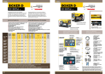
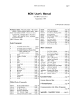
PRODUCT SELECTION TABLE
!!:!-
e-,
z
0
ERT-01
15-100 h
ERTC-01
Multi-function T. Relay
15-100 h
MCB-7
Time Relays
O,1s-30h
MCB·8
Time Relays
O,ls - 999 min
Time.Relays
.•
O,ls - 60 h
~~
MC8-9
-~~.".-.~.~.,
~.~
~
~
,a",,,-"5
.<:
Qi
0
"-c
Z5
"-0
OU ou
~.!:
Q)Q
Ob
!:g.
-g~ .c:;;
~:;
'" u::'"
~.~
0>.<:
.!:~
:;
Cl.
U
'C:
"'''
le8
g'£
oo"i
a>
to)
to)
:;
Cl.
0
0
to)
()
(/)
U>
:gg
~c
~~ m
E
~8
(E
ERTC-01
c
~
0>
•••
• ••
••
•
•
••
••
"-~.~=~~~,=-
Cil
!:g.
i!l.
Ol
Qi
'" a'" ~e
a
u,
u,
Time
Multi-function T. Relay
g
j-:;
,.,0- ~~
,.,c:
~.:= m-
c-,
Product Table
MCB·9
MCB·20
DG·60
s:
0
0
Z
0
eC
E
»,
(JJ
Q;
EO
'"
u;
'"
Q;
s:
(/)
'"
u:::
u,
u,
0
Q;
E
~c
;:
0
a
••• •
•••
aiE u
.l!l
Qi
a.!.
~
:c0>
oc
--'
~a>
0>-
~
:g ~
U
Cl
..,.
..,.
Cl
c
0
1::
~
N
N
U
(
..,.(
"'-0 _a
u
>~ ~
oa>
za
0
'<t
N
~
N
~
(')
N
•
N
16
16
10
10
10
•
-». -."~---,----~'
MCB-15
Multi-function T. Relay
0,055 - 100 h
MCB-20
Multi-function T. Relay
Otls - 100 h
MCB-30
Time Relays
2-30s
MCB-60
Time Relays.
SER-YU
Star-Delta Relays
4-605
(AlU) 20-500ms
CA) 1-60s
SSR-2X
Left-Right Relays
0,15-60 h
DG-10
Time Relays
0,65 -10m
DG-60
Time Relays
EF-10
Flasher Relays
EF-10T
Flasher Relays
ERB-50
Washing
M, Relay
•
••
•
•
•
••
•
•
• •
•
<1~~~10-s'' '1' ' '0' ' ,5'' 's'-' ' ' ~-"~
'"
U>
o
0..
•
-_~~~=n~_.
__.rr__
< --~
'~'
Washing
30,
60,
90,120,180''*s,'=~-"'-----~-------''''~------'-----'''"'''''''''----~
Waiting 35, Rinsing 1-305
~
10
1,0
10
10
10
24
10
••
10
10
••
•
""'-'"
20
SPECIFICATIONS
Operating Voltage
230VAC&
24VAC/DC
~-,==~-
Operating Rang~e~~ __
Power Consumption
230 VAC
for Un±%20(AC) ;
<3VA
<BVA
•
,,=WR-O=- ~-~.~,~
w~"-n1"'0"'"0-m-se-cr
±%O,1
Ambient Temperature;
SA,
2000VA,
coscp=1
2000VA,
coscp=1
•
·51 +50'C ;85 %
Huml Ity
•
Mounting
c.0i!nection Typ,;';e;;;;s,--~>_~Jc_~~
80 m88C,,~£ __
1 CO;
SA,
2CO;
~ __ ~~
"'-_,
~~__
Rail Mounted,terminal with screw
Singl~J2hase 2 wires
PDF processed with CutePDF evaluation edition www.CutePDF.com
80
Print
Data:
032013
120 mS8C"r
2 NO;
__
1 CO;
-,, __
~ .l
Trlyak;
5A,1250VA 6A,4000VA 8A,600VA
Functions of MCB-15 and MCB-20 (12rv 240V AC/DC)
ON Delay (Er) [MCB-15 & MCB~20]:
When the supply voltage U is applied, the set interval t begins (green LED utt flashes).
the interval t has expired (green LED U/t illuminated) the output relay R switches into
on-position
(yellow
interrupted.
If the supply voltage
already
expired
LED illuminated).
This status remains
is interrupted
is erased and restarted
until the supply voltage
LED illuminated)
expired
when the supply voltage
is interrupted
off-position
The interval already
R~
expired
:
into on-position
is interrupted.
(yellow
LED
Em-2
and restarted
into
when the
is next applied.
OFF Delay with control input (R) [MCB-15 & MCB-20] :
The supply voltage U must be constantly applied to the device (green LED Utt illuminated).
When the control contact S is closed, the output relay R switches into on-position (yellow LED
illuminated).
If the control contact
After the interval t has expired
off-position
(yellow
is opened,
the output relay switches
If the control contact
the interval already
of control contact
R
the set interval t begins (green LED flashes).
(green LED utt illuminated)
LED not illuminated).
interval t has expired,
opening
LEDU~t~
If the supply
the output relay switches
is erased
(yellow
After the interval t has
into off-position
until the supply voltage
before the interval t has expired,
immediately.
supply voltage
the output relay R switches
the output relay switches
This status remains
LEDU~t~
is next applied.
and the set interval t begins (green LED Utt flashes).
(green LED U/t illuminated)
not illuminated).
voltage
U is applied,
Er
is
before the expiry of the interval t, the interval
Single shot leading edge voltage controlled (Em) [MCB-15 & MCB-20]
When the supply voltage
After
expired
LEDU~5i§E
S
R
t
<t.
into
is closed again before the
is erased and restarted
at the next
S.
ON Delay with control input (Es) [MeB-20]:
The supply voltage
U must be constantly
applied
to the device (green LED Utt illuminated).
When the control contact S is closed, the set interval t begins (green LED Utt flashes).
the interval t has expired (green LED Utt illuminated) the output relay R switches into
on-position
(yellow
LED illuminated).
This status remains
until the control
again. If the control contact is opened before the interval t has expired,
expired is erased and restarted with the next cycle.
contact
Es
After
LEDU~~
R~
is opened
the interval
already
Single shot leading edge with control input (Ts) [MCB-20) :
The supply voltage U must be constantly applied to the device (green LED Utt illuminated). When the
Ts
control contact S is closed, the output relay R switches into on-position (green LED utt illuminated) and
the set interval t begins (green LED Utt flashes). After the interval t has expired (green LED utt
illuminated) the output relay switches into off-position (yellow LED not illuminated). During the interval,
the control contact can be operated any number of times. A further cycle can only be started when the
cycle run has been completed.
Single shot trailling edge with control input (Ta) [MCa-20]
The supply voltage
U must be constantly
Closing
contact
the control
control contact
is opened,
applied to the device
S has no influence
on the condition
the output relay switches
and the set interval t begins (green LED Utt flashes).
LED U/t illuminated),
the output relay switches
:
(green LED U/t illuminated).
of the output R. When the
into on-position
(yellow
Flasher (Et) [MCB-15 & MCa-20]
_
(green
of times. A further
cycle
the set interval t begins (green LED U/t flashes).
After
:
U is applied,
into off-position
LEDU~~
S
R
LED not illuminated).
the interval t has expired, the output relay R switches into on-position (yellow LED
illuminated) and the set interval t begins again. After the interval t has expired, the output
relay switches
Ta
LED illuminated)
After the interval t has expired
into off-position
During the interval, the control contact can be operated any number
can only be started when the cycle run has been completed.
When the supply voltage
(yellow
(yellow
at a ratio of 1: 1 until the supply voltage
LED not illuminated).
The output relay is triggered
is interrupted.
81
Print Date: 03.2013
Ef
U :
Supply Voltage
ij: Rea.y
Vobge
Common
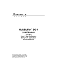
Functions
of MCB-7/8/9;
ERTC-01; EF-10/10T
On Delay (Er)
A
u __ ----_
In the On Delay mode, after the device is energized, the timer starts to
count up and when it reaches the adjusted time, the relay is energized.
• t
L.•
DELAY - ON
~.J:·JIo~fflll ••••
DELAY: - OFF
~-!~~!- _
(3)16~
(2)180
t
Off Delay (Em-1)
In the Off Delay mode, after the device is energized and with start input,
the relay is energized and becomes de-energized
u __ ----_
at the end of the time
adjusted by the user.
(1)15
a24al
• t
• t
Ion
Down Timer
In the Down Timer mode, after the device is energized,
counter starts to count down from the time adjusted
the down
by the user and
when it reaches zero, the relay is energized.
u
ON FLASHER
Flasher
~ ~
~
In the Flasher mode, after the device is energized, when tOFF time ends the relay
is energized and becomes de-energized
at the end of the delay. The starting mode
of the flasher mode can be chosen as ON or OFF mode. In the OFF mode flasher
starts with tOFF and energized after the tOFF value, then continues to tOn mode.
In the On mode flasher starts with tOn and deenergized
then continues
Functions
to tOFF mode. The Flasher function
~: Relay Voltage
• t
~
~
t,:
141 ••••
•
~ ~
•••
:
'++=:
t,: :
III
• t
3(6)~2(5)
•t
.,4a.
is also kept during "t," time.
of DG-06 / DG-10 / DG-60
is off, relay stays energized
during
R
Machine Relay
of 220 V. After the waiting
(No Voltage,
Delayed Impulser)
(ERB-30/50)
time of the selected
is turned off. After a fixed waiting
terminal,
uJ
220 V at the Wash
time(1 Os for Erb-30,
(Rinse) gives an output of 220 V. Rinsing
the device
has to be turned
...•.
t
WaShing~ ~ •••
3s for Erb-50),
twashing
_~
__
-cf
141
-+. t
....••t
for PK21/PK15,
off and on again.
for PK25),
is applied,
are closed
the star contacts
and
operating time, tA• The delta contacts [(2/15,
of the transition
then
3/18)
[(1/16,
released
transition
2/15)
after
the
for PK21/PK15]
are
time, t" = 50 msec (fixed at factory).
time is ± 5 msec.This
u
STAR
• t
• t
~A
to
The fault
DELTA
W
: lmsl
~ll
• t
time can be adjusted
rnsec.) in PK25 type.
Circuit Plan
Main Connection
L1----+----------
2115
1(a3)
j
Note: 24 VAC/DC
-cf
E
018
voltage
closed after the transition
o Rinse
A1.LA2
trinsing
of SER-Y/U
the operating
Eo Wash
A1
!
~
Rinsing r1
time can be
adjusted between 1 and 30 seconds by using the trimmer on the device. After
the adjusted rinsing time, 220 V at the Rinse terminal is turned off. In order to
redo the same operation,
,-iL
-t-•...•
. tOff'
When the device is energized after one of T1, T2, T3, T4, T5 terminals is
short-circuited
with the TO terminal, washing terminal (Wash) gives an output
rinsing terminal
-...;...!
At the end of that time, output relay turns OFF.
If the supply is applied before toff time isn't up, output relay
continues to stay energized.
(to= 20-500
2-3: Right
5-6: Left
OFF" and the right output
ON", and this situation
toff time.
Functions
• t
t...
U_ •••••••
u Operating Voltage r'l
is kept for "t," times. At the end of this
When the supply voltage
When
• t
• • •
repetitive.
the right output relay starts to
period, the left output relay "switches
relay "switches
terminal
: toff
• t
C
is applied,
OFF and this condition
Washing
~
• •
of SSR-2x
When the line voltage
adjusted
U
after the tOn value,
is continuously
work as "switching ON" and the left output relay as "switching
OFF". At the end of "t," time both of two output relays switch
Functions
OFF FLASHER
ton
• t
supply of SER - Y/U is applied
between
~
A2-A3
82
Print Date: 03.2013
ea
1/;6~n~- 3/18
15
016
4
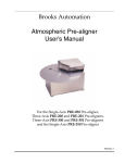
ime Relays
MCB - SER - ERT - SSR - DG Series
Connection Diagram
Dimensions
.~~74:=~.
II~
I
50.
I.
I
Auxiliary
Supply
l~rT<~d}l
*
000000
ERB-50
Bula~lkMaklnasl
Rolesi
00000
I
o
o
o
1$
t, •••
60
,--
I
00
00
TYPE: PK 10
000000000
~e~~~
) I
...r::-
=)
~
I
l
=1
-I-
D +1
0
en
L-
........
IT
000000000
I•
"="
.1
53
TYPE PK 20
(+)
'10 D
(+)
u-
u
(-)
-
I. '~'.I
80
I~I
(-)
s
15
jeA1 B1.
~
A1
,,
r
15
$ ~l
A1
~I
15
cc
$ ~l
I
rpl
L:_
A2 16 18
TYPE PK21
15
leA1 B1
,
I
I
I
0
A2 16 18
000
,
,
I
'----
A2·
16 18
Using MCB-20 with trigger input
:
I
2"81
I
A2·
16 18
en
I-----<
1
•
•
48
58
•
I-I
19
•
TYPE PK22
Without using MCB-20 with trigger input
••••
.
-02
~~~IO
IAI
1 2
3
••••
~rEij]I~
..........
l2ITJ
I~
TYPE PK 28
:~
®®
12
Rail mounted
plastic for
DIN types
A1-A2 : 230 VAC
A3-A2 : 24 VAC/DC
~~IOIO
Un : 220 - 230 VAC
---e'"'e-: 1 C/O, 4000 VAI
diagrams
are given for reference.
Please
always
check the latest user manual
16A
: 50/SO Hz
f
Connection
f: ~j~
I I
I
Un-
given with product
or download
from www.entes.com.tr
83
Print Date: 032013
o®
®®®®
_H_17,5
TYPE PK27