1
Catalog No.BKC0011
DIN EN ISO 9001
JIS Z 9901
Certificate:09 100 5919
Anlagentechnik GmbH
ISO 14001, JIS Q 14001
Certificate-No.: 09 104 8118
ROTARY ACTUATORS
RAT Series
ROTARY ACTUATORS
RAT Series
Light Weight and Compact
■High precision by using bearing.
■Work is easily mounted on the RAT table.
type and 180゜
type.
Two types are available for swing angle, 90゜
By adjusting thread length of rubber stopper or shock absorber, ±5°° adjustment
at the end of swing stroke is possible.
90˚type
Application example
Pick up work piece by
vacuum pad at the arm
end, and rotate the arm
to transfer.
Z slider
(One surface for RAT 5)
c
c
c
c
c
c
c
c
c
q
K
c
Piping direction can be selected for four surfaces.
This enables easy piping in confined spaces or in work installed condition.
For the piping location and swing direction, see p.23.
c
Piping and adjusting swing angle is
possible on one surface throughout
the product range.
By using a vertical lead wire sensor,
even lead wire can be run out in the
same surface. (Except RAT5)
Piping connection is possible on four surfaces.
c
Piping and adjusting swing
angle are possible on one
surface.
Caution
Always read the “Safety Precautions” on page 3 before use.
INDEX
Four types of cushioning are possible.
The same mounting thread is used for both the
rubber stopper and shock absorber. This allows for
change of the rubber stopper to a shock absorber if
required later on, or vice versa.
【With rubber stopper on
both sides】
【With shock absorber
on both sides】
【With shock absorber
on right side】
(Mounted at clockwise rotation end)
【With shock absorber
on left side】
(Mounted at counterclockwise rotation end)
3 types of torque, 0.5, 1.0, 3.0 N・m
are available.
Note
Characteristics
Safety Precautions
Handling Instructions
and Precautions
Air Flow Rate and
Air Consumption
Selection
Specifications
Order Code
Inner Construction,
Major Parts and Materials
Dimensions
Sensor Switch
1
3
7
9
11
20
21
22
24
28
[0.4, 0.7, 2.2 lbf・ft]
Note: At operating
pressure
0.5MPa [73psi.],
and nominal
value.
180˚type
Creceed
Screw fastening unit
Application example
Swing work
Locating hole on table and bottom of the body are available.
Embedded type sensor switch
is available.
Sensor switch mounting groove is
available on two surfaces. For RAT5,
it is available on one surface.
c
c
c
c
Locating hole and mounting hole are common between 90° and 180° types.
Dimensions of those are different in longitudinally only; consequently replacement
between 90° type and 180° type is easy.
For details in dimensions, refer to pages 24 to 27.
w
K
Safety Precautions (Rotary Actuators RAT Series) Always read these precautions carefully before use.
Before selecting and using products, please read all the Safety Precautions carefully to ensure proper product use.
The Safety Precautions shown below are to help you use the product safely and correctly, and to prevent injury or damage to assets
beforehand.
Follow the Safety Precautions for: ISO4414 (Pneumatic fluid power—Recommendations for the application of equipment to
transmission and control systems), JIS B 8370 (Pneumatic system regulations)
”“WARNING!”
”
The directions are ranked according to degree of potential danger or damage: “DANGER!”
“CAUTION!”
”and “ATTENTION!”
”
DANGER
Expresses situations that can be clearly predicted as dangerous.
If the noted danger is not avoided, it could result in death or serious injury.
It could also result in damage or destruction of assets.
WARNING
Expresses situations that, while not immediately dangerous, could become dangerous.
If the noted danger is not avoided, it could result in death or serious injury.
It could also result in damage or destruction of assets.
CAUTION
Expresses situations that, while not immediately dangerous, could become dangerous.
If the noted danger is not avoided, it could result in light or semi-serious injury.
It could also result in damage or destruction of assets.
ATTENTION
While there is little chance of injury, this content refers to points that should be observed for
appropriate use of the product.
■This product was designed and manufactured as parts for use in General Industrial Machinery.
■ Before selecting the equipment and using any product, always read the Safety Precautions, the Catalog, the Instruction Manual, etc.
■ After reading the Instruction Manual, etc., always place the Manual where it can be easily available for reference to users of this product.
■ If transferring or lending the product to an another person, always attach the Instruction Manual, etc., to the product where it is easily
visible, to ensure that the new user can use the product safely and properly.
■ The danger, warning, and caution items listed under these “Safety Precautions” do not cover all possible cases. Read the catalog
and user’s manual carefully, and always keep safety first.
DANGER
● Do not use for the purposes listed below:
1. Medical equipment related to maintenance or management
of human lives or bodies.
2. Mechanical devices or equipment designed for the purpose
of moving or transporting people.
3. Critical safety components in mechanical devices.
This product has not been planned or designed for purposes
that require advanced stages of safety. It could cause injury to
human life.
● Do not use in locations with or near dangerous substances
such as flammable or ignitable substances. This product is
not explosion-proof. It could ignite or burst into flames.
● When attaching the product, always ensure that it is securely
fixed in place. Dropping or falling the product or improper
operation could result in injury.
● Persons who use a pacemaker, etc., should keep a distance
of at least one meter away from the product. There is the
possibility that the pacemaker will malfunction due to the
strong magnet built into the product.
● Never attempt to remodel the product. It could result in
abnormal operation leading to injury, electric shock, fire, etc.
● Never attempt inappropriate disassembly or assembly of the
product’s basic configurations, or of its performance or
functions. It could result in injury, electric shock, fire, etc.
● Do not splash water on the product. Spraying it with water,
washing it, or using it underwater could result in malfunction
of the product leading to injury, electric shock, fire, etc.
● While the product is in operation, avoid touching it with your
hands or otherwise approaching too close. In addition, do not
make any adjustments to the interior or to the attached
mechanisms (removal, etc., of swing adjustment mechanism,
sensor switch mounting position, piping tubes, or sealing
plugs) while in operation. The actuator can move suddenly,
possibly resulting in injury.
● When operating the product, always install a speed controller,
and gradually loosen the needle valve from a choked state to
adjust the speed increasing. Failure to make this adjustment
could result in sudden movements, putting lives at risk.
e
WARNING
● Do not use this product in excess of its specification range.
Such use could result in product breakdowns, function stop or
damage.
● Before supplying air or electricity to the device and before
starting operation, always conduct a safety check of the area
of machine operation. Unintentional supply of air or electricity
could possibly result in electric shocks, or in injury caused by
contact with moving parts.
● Do not touch the terminal and the miscellaneous switches,
etc., while the device is plugged in. There is the possibility of
electric shock and abnormal operation.
● Do not allow the product to be thrown into fire. The product
could explode and release toxic gases.
● Do not sit on the product, place your foot on it, or place other
objects on it. Accidents such as falling and tripping over could
result in injury. Dropping the product may damage or break the
product resulting in abnormal, improper or erratic operation.
● When conducting any kind of operation for the product, such
as inspection, repair, installation/removal of piping, or
replacement, always turn off the air supply completely and
confirm that residual pressure inside the product or in piping
connected to the product is zero before proceeding. In
particular, be aware that residual air will still be in the air
compressor or air storage tank. The actuator could abruptly move
if residual air pressure remains inside the piping, causing injury.
● Do not use the actuator for equipment whose purpose is
absorbing the shocks and vibrations of mechanical devices. It
could break and possibly result in injury or in damage to
mechanical devices.
● Avoid scratching the cords for the sensor switch lead wires, etc.
Letting the cords be subject to scratching, excessive bending,
pulling, rolling up, or being placed under heavy objects or
squeezed between two objects, may result in current leaks or
defective continuity that lead to fires, electric shocks, or
abnormal operation.
● Do not subject the sensor switch to an external magnetic
field during actuator operation. Unintended movements could
result in damage to the equipment or in personal injury.
● Use within the recommended load and specified frequency.
Use exceeding the recommended load and specified
frequency could damage the table, etc., and raise the
possibility of damage to equipment or of personal injury.
Such operation will also drastically reduce the unit’s operating
life.
● Use safety circuits or system designs to prevent damage to
machinery or injury to personnel when the machine shuts
down due to emergency stop or electrical power failure.
● Install relief valves, etc., to ensure that the actuator does not
exceed its rated pressure when such pressure is rising due
to external forces on the actuator. Excessive pressure could
lead to breakdown and damage.
● In initial operations after the equipment has been idle for 48
hours or more, or has been in storage, there is a possibility that
contacting parts will stick, resulting in equipment operation
delays or sudden movements. For these initial operations,
always run a test operation before use to check that operating
performance is normal.
CAUTION
● Do not use in locations under direct sunlight (ultraviolet), in
locations subject to dust, salt, or iron powder, in locations
with humidity, or in the media and/or the ambient atmospheres that include organic solvents, phosphoric esterbased hydraulic fluids, sulfur dioxide gas, chlorine gas and
acids. These conditions could lead to functional shutdowns,
sudden degraded performance, or shortened operating life in
a brief period of time. For the materials used, see Major
Parts and Materials.
● When mounting the product, leave room for adequate
working space around it. Failure to assure adequate working
space will make it more difficult to conduct daily inspections
or maintenance, which could eventually lead to system
shutdown or damage to the product.
● Do not bring floppy disks or magnetic media, etc., within one
meter of the product. There is the possibility that the data on
the floppy disks will be destroyed due to the magnetism of
the magnet.
● Do not use the sensor switch in locations subject to large
electrical currents or strong magnetic fields. It could result in
erratic operation. In addition, do not use magnetized
materials in the mounting bracket. The magnetism could
leak, possibly resulting in erratic operation.
● Never use another company’s sensor switch with these
products. It could possibly cause error or accidental operation.
● Do not scratch, dent, or deform the actuator by climbing on
the product, using it as scaffold, or placing objects on top of
it. It could result in damaged or broken products that result in
operation shutdown or degraded performance.
● When performing mounting or adjustment work, put up "now
working" signs to prevent unintentional supplying air or
electrical power, etc. Such accidental supplies may cause
electrical shock, or sudden activation of the actuator that
could result in physical injury.
● Do not pull on the cords of the lead wires, etc., of the sensor
switches mounted on the actuators, grab them to lift, or place
heavy objects or excessive loads on them. Such action could
result in current leaks or defective continuity that lead to fires,
electric shocks, or abnormal operation.
ATTENTION
● When considering the possibility of using this product in
situations or environments not specifically noted in the
Catalog or user’s Manual, or in applications where safety is
an important requirement, such as in an airplane facility,
combustion equipment, leisure equipment, safety equipment
and other places where human life or assets may be greatly
affected, take adequate safety precautions such as
application with enough margins or fail-safe measures for
ratings and performance. Please consult KOGANEI with any
questions.
● Always check the catalog and other reference materials for
product wiring and piping.
● Use a protective cover, etc., to ensure that human bodies do
not come into direct contact with the operating section of
mechanical devices, etc.
● Do not control in a way that would cause work to fall during
power failure. Set the controls so that they prevent the table
or work, etc., from falling during power failure or emergency
stop of the mechanical devices.
● When handling the product, wear protective gloves, safety
glasses, safety boots, etc., to assure safety.
● When the product can no longer be used, or is no longer
necessary, dispose of it appropriately as industrial waste.
● Pneumatic equipment can exhibit degraded performance and
function over its operating life. Always conduct daily
inspections of the pneumatic equipment, and confirm that all
requisite system functions are satisfied, to prevent accidents
from happening.
● For inquiries about the product, contact your nearest Koganei
sales office or Koganei overseas division. The address and
telephone number is shown on the back cover of this catalog.
OTHER
● Always observe the following items.
1. When using this product in pneumatic systems, always
use genuine KOGANEI parts or compatible parts
(recommended parts).
When conducting maintenance and repairs, always use
genuine KOGANEI parts or compatible parts (recommended parts). Always observe the required methods.
2. Do not attempt inappropriate disassembly or assembly of
the product relating to basic configurations, or its
performance or functions.
Koganei cannot take responsibility for behavior in intentional
disregard of these safety precautions.
r
Safety Precautions (Sensor Switch)
Always read these precautions carefully before use.
Design and Selection
Installation and Adjustment
Warning
Warning
1.Check the specifications.
As use of this equipment over the specified ranges of voltage,
current, temperature, shock, etc., could result in breakdown
or abnormal operation, always read the specifications
carefully to ensure correct use.
2.Avoid mounting actuators in close proximity.
Mounting two or more actuators with sensor switches in close
proximity could result in erroneous operation of the sensor
switch, due to magnetic field interference with the system.
3.Caution about sensor switch ON time for positioning detection at intermediate stroke position.
Take caution that if the sensor switch is mounted at an
intermediate position of the actuator stroke for detection of
the piston travel, the sensor switch actuation time may be too
short when the actuator speed is very rapid, so that the load
(sequencer, etc.) may fail to activate.
Maximum cylinder speed for positioning detection
V〔mm/s〕[in./s]=
Sensor switch actuation range〔mm〕[in.]
Time required for activating load〔ms〕
×1000
4.Keep wiring as short as possible
In reed sensor switches, in particular, excessively long wiring
(10m or more) can shorten the operating life of the sensor
switch with capacitive surges. If the wiring must be long,
install the protection circuits listed in the catalog for inductive
or capacitive loads, as well.
5.Avoid repeated or excessive bending or pulling of
lead wires.
Applying repeated bending stress or tension force on the lead
wire could result in wire breakage.
6.Check for leak current.
4.Two-lead wire solid state sensor switches produce leak current to
activate their internal circuits, and the current flows even when
turned off condition. Check to ensure they satisfy the following
formula.
Input off current of programmable controller > Leak current
If the above formula cannot be satisfied, select a three-lead wire
solid state sensor switch, instead. Also note that parallel
connection of a total of n sensor switches will lead to n times the
leak current.
Caution
1.Check for sensor switch internal voltage drop.
Series connection of reed sensor switches with indicator
lamps or two-lead wire solid state sensor switches causes
increasing internal voltage drop, and the load may fail to
activate. A total of n sensor switches will lead to n times the
internal voltage drop. Ensure that the system satisfies the
following formula.
Supply voltage – Internal voltage drop × n > Minimum
operating voltage for load
In relays with rated voltage of less than 24VDC, check to see
whether the above formula is satisfied, even in the case of n = 1.
If the above formula cannot be satisfied, select either a reed
sensor switch without indicator lamp, or a three-lead wire
solid state sensor switch.
2.Do not use with other companies’ actuators.
The sensor switches are designed for use with Koganei
actuators. Use with other companies’ actuators could lead to
abnormal operation.
t
1.Do not subject the sensor switch to an external
magnetic field during actuator operation.
Unintended movements could result in damage to the
equipment or in personal injury.
Caution
1.Ensure a safe mounting environment for the
actuators with sensor switches.
Do not use sensor switches in places where large current or
magnetic fields are present. This could lead to unintentional
operation. Do not use magnetic material for the mounting
brackets. It could result in erratic operation.
2.Install sensor switches in the center of its operating
range.
Adjust the mounting position of a sensor switch so that the
piston stops in the center of its operating range (the range
while the sensor turns on). Operations can be unstable if
mounted at the end of the operating range (at the boundary
near ON and OFF). Also be aware that the operating range
can vary with changes in temperature.
3.Follow the tightening torque of sensor switches
when mounting.
Over-tightening beyond the allowed fastening torque may
damage the mounting screws, mounting brackets, sensor
switches, etc. In addition, insufficient tightening torque could
cause the sensor switch position to change, resulting in
operating instability.
For the tightening torque, see p.31.
4.Do not attempt to transport the actuator while the
sensor switch lead wires are attached.
After mounting a sensor switch to a actuator, do not grab the
lead wires to lift the actuator. Never do this, as it could result in
lead wire disconnections, and could also apply stress to the
interior of the sensor switch, resulting in breakage of internal
elements.
5.Do not drop switches, or bump them against others.
During handling of switches, do not apply excessive shocks
(294.2m/s2 {30G} [965ft/s2] or more) such as hitting, dropping, or
bumping. In reed sensor switches, the contact reed can be
activated unintentionally, causing it to send or break sudden
signals. It can also cause changes in the contact interval that
lead to changes in sensor switch sensitivity and result in
erratic operation. Even if the sensor switch case is
undamaged, the inner parts of the sensor switch may suffer
breakdown or erratic operation.
General Precautions
Wiring
Danger
1.Avoid letting moving objects near a sensor switch
come into contact with them.
When actuators with sensor switches move, or when moving
objects are nearby, do not let the moving objects come into
contact. In particular, lead wires could become worn out or
damaged, inducing operating instability in the sensor switch. In
the worst case, it could result in current leaks or electrical shocks.
Media
1. Use air for media. Consult with us for the use of any other
media.
2. For the air used in the rotary actuator, use clean air that does
not contain deteriorated compressor oil. Install a filter
(filtration rate of 40μm or less) near the rotary actuator or
valve to remove collected liquid or dust. Also, clean out the
collected liquid of the air filter on a regular basis.
2. Always turn off the power supply for wiring work.
Conducting wiring work while the power is on could result in
electric shocks. Also, incorrect wiring could damage sensor
switches in an instant. Turn on the power only after wiring
work is complete.
Warning
1.Check the Catalog, etc., to ensure that the sensor
switch wiring is correctly connected.
Piping
1. Always flush out the piping (blow through with compressed
air) before connecting the rotary actuator. Entering cutting
chips, sealing tape, rust, or other materials generated during
plumbing could result in air leaks or other operational
malfunctions.
2. Observe the following tightening torques when screwing
piping or fittings into the rotary actuator.
Miswiring could result in abnormal operation.
2.Do not share the same wiring with power or high
voltage lines.
Avoid wiring in parallel to or shared with power or high voltage
lines. The sensor switch or control circuit may suffer electric noise
that results in erratic operation.
3.Avoid repeated or excessive bending or pulling of
lead wires.
Applying repeated bending stress or tension force on the lead
wire could result in wire breakage.
Connecting thread
Tightening torque N・cm{kgf・cm} [lbf・ft]
M5×0.8
157{16} [1.16]
Lubrication
This product can be used without lubricating oil. If lubrication
must be used, use turbine oil Class 1 (ISO VG32) or its
equivalent. Do not use spindle oil or machine oil.
4. Check polarity in the wiring
In sensor switches that specify polarity (+, –, output), be sure
that wiring connections are correct. The wrong polarity could
result in damage to the sensor switch.
Atmosphere
If using in locations in oily or wet surroundings, protect with a
cover, etc.
Caution
1. Avoid short circuiting the loads.
Turning a sensor switch on while the load is short-circuited
causes overcurrent, which can damage the sensor switch in
an instant.
Example of short-circuited load: Sensor switch’s output lead
wire is directly connected to the power supply.
Start-Up
When starting up operations of a device and the rotary actuator
by supplying compressed air rapidly, it could not control the
speed due to the structure of the rotary actuator, resulting in
damage to the device and rotary actuator. When supplying
compressed air to a device and the rotary actuator where the air
has been exhausted, always ensure that the table is in a secure
position and cannot be moved further, paying attention to
safety, and then apply air pressure from the connection port of
not making move the table. For the piping location and swing
direction, see p.23.
y
Handling Instructions and Precautions
Mounting
1. Models with rubber stoppers on both sides can be freely
mounted in any direction. If using models with shock
absorbers (-SS2, -SSR, -SSL), however, avoid using with the
shock absorber mounted on top of the body. This position
drastically reduces the shock absorber’s operating life.
When using with shock absorber, locate the shock absorber
so that it is mounted on the bottom or side of the body.
Work
Bolt for mounting
work in place
Table
Thread depth L
Mounting
Top
Shock absorber
on top
Angle adjusting bolt
or shock absorber
Model
RAT5
RAT10
RAT30
Bottom
Top
Top Shock absorber
on the side
Top
Thread size
Thread depth
L mm [in.]
Maximum tightening
torque
N・m [lbf・ft]
M4×0.7
7 [0.28]
1.37 [1.01]
M6×1.0
8 [0.32]
4.80 [3.54]
Caution: When using a bolt to mount the work in place on the table, hold
either the table or work in place during the operation. Holding the
body in place for tightening will apply excessive moment to the
stopper, rubber stopper and shock absorber, resulting in a change
of angle.
6. The rotary actuator RAT series can be mounted in either of
the two ways shown below. When mounting, ensure that the
tightening torque is within the range of allowable values.
Shock absorber on the bottom
Bottom
Bottom
Bottom
2. Ensure that the mounting surface is flat. Twisting or bending
during the mounting could result in air leaks or defective
operation.
3. Avoid scratching or denting the mounting surface of the
rotary actuator, as it could damage the flatness.
4. Shocks or vibrations might loosen the bolt, consider taking
loosening preventive measure, etc.
5. For work mounting, female threads are available for installing
the work in place on the table. Always use bolts so that the
screw length is less than the depth of the female thread. Use
longer bolts than the female thread will interfere with the
angle adjusting bolt or shock absorber, and prevent them
from working properly. When mounting the work, tighten the
bolts within the range of the tightening torque.
Female thread for mounting
work in place
u
Mounting using the through
holes on the body
Mounting using the tap
on the body
Mounting method
Thread size
Maximum tightening
torque
N・m [lbf・ft]
RAT5
Through hole
M5×0.8
2.84 [2.09]
RAT10
Female thread
M6×1.0
4.80 [3.54]
Through hole
M6×1.0
4.80 [3.54]
Female thread
M8×1.25
12.0 [8.85]
Model
RAT30
Handling Instructions and Precautions
Rubber stopper and shock absorber replacement instructions
Loosen and remove the mounting nut of the rubber stopper or
shock absorber. Screw in the new rubber stopper or shock
absorber to the proper position, and then tighten the mounting
nut and fix in place. When tightening the nut, ensure that the
tightening torque is within the range of setting values.
Mounting nut
Shock absorber
Rubber stopper
Swing angle adjustment
1. The rotary actuator RAT series uses rubber stoppers or
shock absorbers for angle adjustment, in the ranges shown
on p.23. For both clockwise and counterclockwise rotation,
rotating the rubber stopper or shock absorber to the right
(clockwise) will reduce the swing angle. After completing
angle adjustment, tighten the nut and fix in place.
2. Always follow the swing angle within the specified range for
use. For the shock absorber, in particular, the angle between
the load applying direction and the axial center line of the
shock absorber exceeds the allowable angle variation, it
could damage the product.
3. The rubber stopper or shock absorber are only temporarily
tightened at time of delivery. For actual use, always tighten
the nut to fix in place.
4. When tightening the nut, ensure that the tightening torque is
within the range shown below.
Model
RAT5
RAT10
RAT30
Nut size
Maximum tightening
torque N・m [lbf・ft]
M8×0.75
2.45 [1.81]
M10×1.0
6.37 [4.70]
i
Air Flow Rate and Air Consumption
●Air consumption for 1 cycle operation
cm3/cycle(ANR)[in.3/cycle]
Air pressure MPa [psi.]
Model
0.2 [29]
0.3 [44]
0.4 [58]
0.5 [73]
0.6 [87]
0.7 [102]
RAT5-90
11.3 [0.69]
15.0 [0.92]
18.7 [1.14]
22.5 [1.37]
26.2 [1.60]
29.9 [1.82]
RAT5-180
22.5 [1.37]
30.0 [1.83]
37.5 [2.29]
44.9 [2.74]
52.4 [3.20]
59.9 [3.66]
RAT10-90
22.5 [1.37]
30.0 [1.83]
37.5 [2.29]
44.9 [2.74]
52.4 [3.20]
59.9 [3.66]
RAT10-180
45.0 [2.75]
60.0 [3.66]
74.9 [4.57]
89.9 [5.49]
104.8 [6.40]
119.8 [7.31]
RAT30-90
61.6 [3.76]
82.0 [5.00]
102.5 [6.25]
122.9 [7.50]
143.3 [8.74]
163.8 [10.00]
RAT30-180
123.2 [7.52]
164.0 [10.01]
204.9 [12.50]
245.8 [15.00]
286.7 [17.50]
327.6 [19.99]
Air consumption
cm3/cycle(ANR)
[in.3/cycle]
1000.0
[61]
RAT30-180
RAT30-90
RAT10-180
100.0
[6.1]
RAT5-180,RAT10-90
RAT5-90
10.0
[0.61]
1.0
0
0.1 0.2 0.3 0.4 0.5 0.6 0.7 0.8
[15] [29] [44] [58] [73] [87] [102] [116]
Air pressure
MPa
[psi.]
Calculation of air flow rate and air consumption
The above graph shows the air consumption for one cycle of the rotary actuator. The actual required air flow rate and air consumption
is found by the following formula. Note that the calculation method varies between ‘‘RAT5’’ and ‘‘RAT10,30’’ due to the difference
between single piston and double piston construction.
●Equation for finding air flow rate (when selecting the F.R.L., valve, etc.)
●RAT5
Q1=
●RAT5
πD2
60 P+0.1013
×L× ×
×10−6
4
t
0.1013
Q1′
=
●RAT10, 30
Q1=
π D′2 L′ 60 P′
+14.7
×
× ×
12
4 12
t
14.7
( ) ( )
●RAT10, 30
πD2
60 P+0.1013
×2×L× ×
×10−6
4
t
0.1013
Q1′
=
π D′2
L′ 60 P′
+14.7
×2×
× ×
4 12
12
14.7
t
( )
( )
●Equation for finding air consumption
●RAT5
●RAT5
Q2=
πD2
P+0.1013
×L×2×n×
×10−6
4
0.1013
=
Q2′
πD2
P+0.1013
×2×L×2×n×
×10−6
4
0.1013
Q1 : Air flow rate required for the cylinder
Q2 : Cylinder air consumption
D : Inner diameter of the cylinder tube
L : Cylinder stroke
t : Time required by the cylinder for one stroke
n : Number of the piston reciprocation
P : Pressure
Q2′
=
R/min (ANR)
R/min (ANR)
mm
mm
s
cycles/min
MPa
●Cylinder bore and stroke
Model
o
( )
●RAT10, 30
●RAT10, 30
Q2=
π D′2 L′
P′
+14.7
× ×2×n×
12
4 12
14.7
Cylinder bore
mm [in.]
Cylinder stroke
RAT5-90
16 [0.63]
9.4 [0.37]
RAT5-180
16 [0.63]
18.8 [0.74]
RAT10-90
16 [0.63]
9.4 [0.37]
RAT10-180
16 [0.63]
18.8 [0.74]
RAT30-90
20 [0.79]
16.5 [0.65]
RAT30-180
20 [0.79]
33.0 [1.30]
π D′2
L′
P′
+14.7
×2× ×2×n×
4 12
12
14.7
( )
Q1′
: Air flow rate required for the cylinder
Q2′
: Cylinder air consumption
D′: Inner diameter of the cylinder tube
L′: Cylinder stroke
t : Time required by the cylinder for one stroke
n : Number of the piston reciprocation
P′: Pressure
ft3/min
ft3/min
in.
in.
s
cycles/min
psi.
Handling Instructions and Precautions
●Allowable load
●Table displacement caused by bending moment
RAT10
RAT30
50 [11.2]
80 [18.0]
200 [45.0]
Allowable radial load WR: N [lbf]
30 [6.7]
80 [18.0]
200 [45.0]
Allowable bending moment M: N・m [lbf・ft]
1.5 [1.1]
2.5 [1.8]
5.5 [4.1]
Item
Model
Allowable thrust load Ws: N [lbf]
100mm [3.94 in.]
Bending moment
Thrust load
WS
In the rotary actuator RAT series, mounting a plate and
applying moment on it, and then measure the displacement at
100mm [3.94 in.] position from the rotation center.
WS
Radial load
WR
WR
WR
μm
[in.]
WR
RAT5
Bending moment
Displacement
80
[3.15x10⁻³]
M
Displacement
RAT5
M
60
[2.36x10⁻³]
RAT10
40
[1.57x10⁻³]
RAT30
20
[0.79x10⁻³]
0
0
1
[0.74]
2
[1.5]
3
[2.2]
Bending moment
●Effective torque
N・m [lbf・ft]
4
[3.0]
5
[3.7]
6
[4.4]
N・m
[lbf・ft]
Air pressure MPa [psi.]
Model
0.2 [29]
0.25 [36]
0.35 [51]
0.3 [44]
0.4 [58]
RAT5
0.12 [0.09]
0.17 [0.13] 0.22 [0.16] 0.27 [0.20] 0.32 [0.24]
RAT10
0.29 [0.21]
0.39 [0.29] 0.49 [0.36] 0.59 [0.44] 0.69 [0.51]
RAT30
1.10 [0.81]
1.40 [1.03] 1.69 [1.25] 1.99 [1.47] 2.28 [1.68]
0.45 [65]
0.5 [73]
0.37 [0.27]
0.42 [0.31]
0.47 [0.35] 0.52 [0.38] 0.57 [0.42] 0.62 [0.46]
0.79 [0.58]
0.89 [0.66]
0.99 [0.73] 1.09 [0.80] 1.19 [0.88] 1.29 [0.95]
2.57 [1.90]
2.87 [2.12]
3.16 [2.33] 3.46 [2.55] 3.75 [2.77] 4.04 [2.98]
Air pressure MPa [psi.]
0.55 [80]
0.65 [94]
0.6 [87]
0.7 [102]
N・m
[lbf・ft]
RAT30
Effective torque
4.0
[3.0]
3.0
[2.2]
2.0
[1.5]
RAT10
1.0
[0.74]
0.0
RAT5
0
0.1
[15]
0.2
[29]
0.3
[44]
0.4
[58]
0.5
[73]
Air pressure
0.6
[87]
0.7
[102]
0.8
[116]
MPa
[psi.]
!0
Selection
Caution: For the load and swing time, follow the below “Model selection method’’ to select within the range of specified values.
Moreover, about 80% of the allowable values is recommended to use in the application. By using these values, adverse
effects on cylinders and guides can be a minimum.
●Model selection method
●Model selection method
1. Check the application conditions
Check the following items q∼r
qSwing angle (90˚ or 180˚)
wSwing time (s)
eApplied pressure (MPa)
rLoad shape and materials
tMounting direction
1. Check the application conditions
Check the following items q∼r
qSwing angle [90˚ or 180˚]
wSwing time [s]
eApplied pressure [psi.]
rLoad shape and materials
tMounting direction
2. Check the swing time
Check the swing time in 1−w is within the swing time
adjustment range in the specification.
2. Check the swing time
Check the swing time in 1−w is within the swing time
adjustment range in the specification.
Angle
Swing time (s)
Swing time [s]
0.2∼1.0
90゜
0.2∼1.0
180゜
0.4∼2.0
180゜
0.4∼2.0
Note: The swing time value is derived by using the rubber stopper with no
load at 0.5MPa condition.
Note: The swing time value is derived by using the rubber stopper with no
load at 73psi. condition.
3. Select torque size (select model)
Find the torque TA required for rotating the body.
3. Select torque size (select model)
Find the torque TA′required for rotating the body.
・
TA = IωK
・ = 2θ
ω
t2
TA : Torque(N・m)
I : Moment of inertia(kg・m2)
Use the formulas on p.13∼16 to find.
・ : Equiangular acceleration(rad/s2)
ω
K : Marginal coefficient 5
θ : Swing angle(rad)
90゜
→1.57rad
180゜
→3.14rad
t : Swing time(s)
・K
= I′
ω
TA′
・ = 2θ
ω
t2
: Torque [lbf・ft]
TA′
I′: Moment of inertia [lbf・ft・s2]
Use the formulas on p.13∼16 to find.
・ : Equiangular acceleration [rad/s2]
ω
K : Marginal coefficient 5
θ : Swing angle [rad]
90゜
→1.57rad
180゜
→3.14rad
t : Swing time [s]
Select the model secures the required torque TA by using the
applied pressure checked in 1−e, from among the effective
torque table or diagram on p.10.
Select the model secures the required torque TA′by using
the applied pressure checked in 1−e, from among the
effective torque table or diagram on p.10.
4. Check the kinetic energy
If kinetic energy exceeds the allowable energy, the actuator
could be damaged. Always select a model so that the energy
remains within the allowable energy range. When the kinetic
energy is large, use a model with shock absorber (-SS2, -SSR,
or -SSL). For the allowable kinetic energy, see Table 1.
Find the kinetic energy.
●With rubber stopper
1
E = × I ×ω2
E : Kinetic energy(J)
2
I : Moment of inertia(kg・m2)
2θ
ω=
Use the formulas on p.13∼16 to find.
t
ω : Angular velocity(rad/s)
θ : Swing angle(rad)
E < Ea
90゜
→1.57rad
180゜
→3.14rad
t : Swing time(s)
Ea : Allowable energy with rubber stopper
... See Table 1.
!1
Angle
90゜
Find the kinetic energy.
●With rubber stopper
1
E′
= × I′
×ω2 E′: Kinetic energy [lbf・ft]
2
I′
: Moment of inertia [lbf・ft・s2]
2θ
ω=
Use the formulas on p.13∼16 to find.
t
ω : Angular velocity [rad/s]
θ : Swing angle [rad]
E′
< Ea′
90゜
→1.57rad
180゜
→3.14rad
t : Swing time [s]
Ea′
: Allowable energy with rubber stopper
... See Table 1.
●With shock absorber
qFind the equivalent mass m1.
●With shock absorber
qFind the equivalent weight w1.
I
R2
m1 =
m1 : Equivalent mass(kg)
I : Moment of inertia(kg・m2)
Use the formulas on p.13∼16 to find.
wFind the equivalent mass m2.
R : Distance from rotation center to impact
2×T×L
point (m) ... See Fig.1 and Table 2.
m2 = 3
R ×ω2
m2 : Equivalent mass(kg)
2θ
T : Effective torque(N・m)
ω=
t
Use the effective torque table or
diagram to find.
eFind the total mass m.
L : Shock absorber stroke(m)
m = m1 + m 2
... See Table 2.
ω : Angular velocity(rad/s)
rFind the impact velocity. θ : Swing angle(rad)
V = R ×ω
90゜
→1.57rad
180゜
→3.14rad
tFind the kinetic energy.
t : Swing time(s)
m : Total mass(kg)
1
V : Impact velocity(m/s)
E = × m × V2
2
E : Kinetic energy(J)
Ea : Allowable energy with shock
E < Ea
absorber ... See Table 1.
Table 1. Allowable energy Ea
Model
Allowable energy with
rubber stopper (J)
Allowable energy with
shock absorber (J)
w1 =
I′
×32.2
2
R′
w1 : Equivalent weight [lb]
I′: Moment of inertia [lbf・ft・s2]
Use the formulas on p.13∼16 to find.
wFind the equivalent weight w2.
R′
: Distance from rotation center to impact
2×T′
×L′
×32.2
point [ft] ... See Fig.1 and Table 2.
w2 =
3 ×ω2
R′
w2 : Equivalent weight [lb]
2θ
T′
: Effective torque [lbf・ft]
ω=
t
Use the effective torque table or
diagram to find.
eFind the total weight w.
L′
: Shock absorber stroke [ft]
w = w1 + w 2
... See Table 2.
ω : Angular velocity [rad/s]
rFind the impact velocity. θ : Swing angle [rad]
V′
= R′
×ω
90゜
→1.57rad
180゜
→3.14rad
tFind the kinetic energy.
t : Swing time [s]
w : Total weight [lb]
1
w
2
V′
: Impact velocity [ft/s]
E′
= ×
× V′
2
32.2
E′
: Kinetic energy [lbf・ft]
Ea′
: Allowable energy with shock
E′
< Ea′
absorber ... See Table 1.
Table 1. Allowable energy Ea′
Model
Allowable energy with
rubber stopper [lbf・ft]
Allowable energy with
shock absorber [lbf・ft]
RAT5
0.005
0.36
RAT5
0.004
0.266
RAT10
0.008
0.53
RAT10
0.006
0.391
RAT30
0.030
1.14
RAT30
0.022
0.841
Fig.1 R: Distance from rotation center to impact point
Fig.1 R′: Distance from rotation center to impact point
R
Table 2.
Model
Distance R′from
rotation center
to impact point [in.]
Shock absorber
stroke L′[in.]
Shock absorber
model
KSHAR5×5-D
RAT5
0.69
0.20
KSHAR5×5-D
KSHAR5×5-E
RAT10
0.69
0.20
KSHAR5×5-E
KSHAR6×8-F
RAT30
0.87
0.31
KSHAR6×8-F
Model
Distance R from
rotation center
to impact point (m)
Shock absorber
stroke L (m)
Shock absorber
model
RAT5
0.0175
0.005
RAT10
0.0175
0.005
RAT30
0.0220
R′
Table 2.
0.008
5. Check the load ratio
Check that the total sum of the load ratio does not exceed 1.
For the allowable load, see Table 3 (For the load direction,
see the allowable load on p.10.)
5. Check the load ratio
Check that the total sum of the load ratio does not exceed 1.
For the allowable load, see Table 3 (For the load direction,
see the allowable load on p.10.)
WS
WR
M
+
+
≦1
M MAX
WS MAX
WR MAX
WR
M
WS
+
+
≦1
M MAX
WS MAX
WR MAX
Table 3. Allowable load
Table 3. Allowable load
Model
Thrust load
WS MAX (N)
Radial load
WR MAX (N)
Moment load
M MAX (N・m)
Model
Thrust load
WS MAX [lbf]
Radial load
WR MAX [lbf]
Moment load
M MAX [lbf・ft]
RAT5
50
30
1.5
RAT5
11.2
6.7
1.1
RAT10
80
80
2.5
RAT10
18.0
18.0
1.8
RAT30
200
200
5.5
RAT30
45.0
45.0
4.1
6. Judgement whether the unit is usable or not
The unit is usable if it satisfies both 4. Kinetic energy and 5.
Load ratio.
E < Ea
Total sum of load ratio ≦ 1
6. Judgement whether the unit is usable or not
The unit is usable if it satisfies both 4. Kinetic energy and 5.
Load ratio.
E′
< Ea′
Total sum of load ratio ≦ 1
!2
Selection
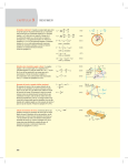
■Diagram for calculating moment of inertia
【When the rotating axis passes through the work】
●Disk
●Diameter
●Mass
d(m)
m(kg)
■Moment of inertia I(kg・m2)
■Rotating radius
md2
8
I=
d2
8
d
●Diameter
●Weight
d [ft]
w [lb]
■Moment of inertia I′[lbf・ft・s2]
I′
=
■Rotating radius
d2
8
wd2
8×32.2
Remark: No particular mounting direction.
For sliding use, see separate materials.
●Stepped disk
d1(m) ■Moment of inertia I(kg・m2)
d2(m)
1
I= (m1d12+m2d22)
●Mass d1 section m1(kg)
8
d2 section m2(kg)
■Rotating radius
●Diameter
■Rotating radius
●Diameter
d1
d2
d1 [ft]
d2 [ft]
●Weight d1 section w1 [lb]
d2 section w2 [lb]
■Moment of inertia I′[lbf・ft・s2]
I′
=
1
×(w1d12+w2d22)
8×32.2
d12+d22
8
d12+d22
8
Remark: The d2 section can be ignored when it is much smaller than the d1 section.
●Bar (rotation center is at edge)
R
●Bar length
●Mass
R(m)
m(kg)
■Moment of inertia I(kg・m2)
I=
●Bar length
●Weight
R[ft]
w [lb]
R2
3
mR2
3
■Moment of inertia I′[lbf・ft・s2]
I′
=
■Rotating radius
wR2
3×32.2
■Rotating radius
R2
3
Remark: Mounting direction is horizontal.
If the mounting direction is vertical, the swing time will change.
●Thin bar
●Bar length
R1
●Mass
R2
●Bar length
●Weight
R1(m)
R2(m)
m1(kg)
m2(kg)
■Moment of inertia I(kg・m2)
R1 [ft]
R2 [ft]
w1 [lb]
w2 [lb]
■Moment of inertia I′[lbf・ft・s2]
I=
I′
=
m1R12
3
+
m2R22
3
w2R22
w1R12
+
3×32.2
3×32.2
■Rotating radius
R12+R22
3
■Rotating radius
R12+R22
3
Remark: Mounting direction is horizontal.
If the mounting direction is vertical, the swing time will change.
!3
●Bar (rotation center is through the center of gravity)
●Bar length
●Mass
R(m)
m(kg)
■Moment of inertia I(kg・m2)
I=
R
●Bar length
●Weight
R[ft]
w [lb]
■Rotating radius
mR2
12
R2
12
■Moment of inertia I′[lbf・ft・s2]
■Rotating radius
wR2
I′
=
12×32.2
R2
12
Remark: No particular mounting direction.
●Thin rectangular plate (rectangular solid)
a1(m)
a2(m)
●Length of side b (m)
●Mass
m1(kg)
m2(kg)
■Moment of inertia I(kg・m2)
●Plate length
■Moment of inertia I′[lbf・ft・s2]
●Plate length
a1
b
a2
●Length of side
●Weight
a1 [ft]
a2 [ft]
b [ft]
w1 [lb]
w2 [lb]
I=
I′
=
■Rotating radius
m2
m1
(4a12+b2)+ (4a22+b2)
12
12
(4a12+b2)+(4a22+b2)
12
■Rotating radius
w1
w2
(4a12+b2)+
(4a22+b2)
12×32.2
12×32.2
(4a12+b2)+(4a22+b2)
12
Remark: Mounting direction is horizontal.
If the mounting direction is vertical, the swing time will change.
●Rectangular solid
●Plate length
●Mass
a
a(m)
b(m)
m(kg)
■Moment of inertia I(kg・m2)
a [ft]
b [ft]
w [lb]
■Moment of inertia I′[lbf・ft・s2]
m
I= (a2+b2)
12
■Rotating radius
a2+b2
12
b
●Plate length
●Weight
I′
=
w
(a2+b2)
12×32.2
■Rotating radius
a2+b2
12
Remark: No particular mounting direction.
For sliding use, see separate materials.
!4
Selection
Concentrated load m1
●Concentrated load
R1
R2
●Shape of concentrated load
●Distance to center of gravity of concentrated load
●Length of arm
●Mass of concentrated load
●Mass of arm
■Moment of inertia I(kg・m2)
R1(m)
R2(m)
m1(kg)
m2(kg)
I=m1k2+m1R12+
m2R22
3
Rotating radius: k2 is calculated according to shape of the
concentrated load.
Remark: Mounting direction is horizontal. When m2 is much
smaller than m1, calculate as m2 = 0.
Arm m2
●Shape of concentrated load
●Distance to center of gravity of concentrated load R1 [ft]
●Length of arm
R2 [ft]
●Weight of concentrated load
w1 [lb]
●Weight of arm
w2 [lb]
■Moment of inertia I′[lbf・ft・s2]
I′
=
w1k2 w1R12
w2 R22
+
+
×
32.2
3
32.2
32.2
Rotating radius: k2 is calculated according to shape of the
concentrated load.
Remark: Mounting direction is horizontal. When w2 is much
smaller than w1, calculate as w2 = 0.
●Gear Equation for calculating the load JL about the rotary actuator axis when transmitted by gear
b
Load Ib
●Gear Rotary actuator side
Load side
●Inertia moment of load
a
b
■Moment of inertia I(kg・m2)
Inertia moment of load around rotating axis
N・m
Ia
Ia=
Rotary actuator
a
●Gear Rotary actuator side
Load side
●Inertia moment of load
a
b
a
b
2
Ib
■Moment of inertia I′[lbf・ft・s2]
Inertia moment of load around rotating axis
lbf・ft
Ia=
a
b
2
Ib
Remark: If the shape of the gear is too large, the inertia
moment of the gear must be also taken into
consideration.
!5
【When the rotating axis is offset from the work】
●Rectangular solid
L
●Length of side
h(m)
●Length from rotating axis to the center of load L(m)
●Mass
m(kg)
■Moment of inertia I(kg・m2)
●Length of side
h [ft]
●Length from rotating axis to the center of load L [ft]
●Weight
w [lb]
■Moment of inertia I′[lbf・ft・s2]
I=
mh2
+mL2
12
h
wh2
wL2
I′
=
+
32.2×12
32.2
Remark: Same for cubical body.
●Hollow rectangular solid
L
h2
h1(m)
h2(m)
●Length from rotating axis to the center of load L(m)
●Mass
m(kg)
■Moment of inertia I(kg・m2)
●Length of side
■Moment of inertia I′[lbf・ft・s2]
●Length of side
h1 h1
h1 [ft]
h2 [ft]
●Length from rotating axis to the center of load L [ft]
●Weight
w [lb]
h2
I=
I′
=
m
(h22+h12)+mL2
12
w
(h22+h12) wL2
+
32.2
32.2×12
Remark: Cross-section is for cubic body only.
●Cylinder
L
d
●Diameter
d(m)
●Length from rotating axis to the center of load L(m)
●Mass
m(kg)
■Moment of inertia I(kg・m2)
●Diameter
d [ft]
●Length from rotating axis to the center of load L [ft]
●Weight
w [lb]
■Moment of inertia I′[lbf・ft・s2]
●Diameter
d1(m)
d2(m)
●Length from rotating axis to the center of load L(m)
●Mass
m(kg)
■Moment of inertia (kg
I ・m2)
●Diameter
■Moment of inertia I′[lbf・ft・s2]
I=
I′
=
md2
+mL2
16
wd2
wL2
+
32.2×16 32.2
●Hollow cylinder
L
I=
m
(d22+d12)+mL2
16
d1
d2
d1 [ft]
d2 [ft]
●Length from rotating axis to the center of load L [ft]
●Weight
w [lb]
I′
=
w
(d22+d12) wL2
+
32.2
32.2×16
!6
Selection
to
ter
cen
ion lid)
t
a
t
ro ic so
om
e fr f cub
tanc nter o 70
s
i
(D
ce
50
●Calculation example
When the load is a
rectangular solid on
a rectangular plate
●Calculation example
When the load is a
rectangular solid on
a rectangular plate
50
(unit: mm)
to
te r
cen
tion lid)
a
t
o
o
r ic s
om
e fr f c u b
6
ta n c e r o
(Dis cent 2.7
7
9
.
1
1 .9
7
8
0.9
50
Rectangular
plate
0.39
25
1.97
(unit: in.)
Rectangular
plate
10
2
4.7
12
0
1 .9
7
50
1. Check application conditions
qSwing angle:90゜
wSwing time:0.5(s)
eApplied pressure:0.5(MPa)
rLoad shape: Shown in the above
Load material
Rectangular plate: Aluminum alloy (Specific gravity =2.68×10³ kg/m3)
Rectangular solid: Steel (Specific gravity =7.85×10 3 kg/m3)
tMounting direction : Horizontal
2. Check the swing time
The swing time is 0.5s/90˚, which is within the range of 0.2∼
1.0s/90˚, and is therefore not a problem.
3. Select by the torque
Firstly calculate the moment of inertia.
Rectangular plate
m1=0.05×(0.12−0.025)×0.01×2.68×103=0.127(kg)
m2=0.05×0.025×0.01×2.68×103=0.034(kg)
I1=
0.127
0.034
{4×(0.12−0.025)2+0.052}
+
(4×0.0252+0.052)
12
12
=0.42×10⁻³(kg・m2)…q
Rectangular solid
m3=0.05×0.05×0.05×7.85×103=0.981(kg)
0.981×0.052
+0.981×0.072
I2=
12
=5.01×10⁻³(kg・m2)…w
From q and w, the total moment of inertia I is
I=I1+I2
=0.42×10⁻³+5.01×10−3
=5.43×10⁻³(kg・m2)…e
According to the conditions,θ=90゜
, t=0.5
(s)
・ is
therefore, the equiangular acceleration ω
2×1.57
・
ω=
=12.56(rad/s2)…r
0.52
From e and r, the required torque TA is
TA=5.43×10−3×12.56×5
=0.341(N・m)…t
From the Effective Torque Table (diagram), select a model
where the torque is more than 0.341 (N・m) at 0.5 MPa.
!7
RAT5-90
1. Check application conditions
qSwing angle:90゜
wSwing time:0.5 [s]
eApplied pressure:73 [psi.]
rLoad shape: Shown in the above
Load material
Rectangular plate: Aluminum alloy (Specific gravity =167 lb/ft3)
Rectangular solid: Steel (Specific gravity =490 lb/ft3)
tMounting direction : Horizontal
2. Check the swing time
The swing time is 0.5s/90˚, which is within the range of 0.2∼
1.0s/90˚, and is therefore not a problem.
3. Select by the torque
Firstly calculate the moment of inertia.
Rectangular plate
1.97 (4.72−0.98) 0.39
×
×
×167=0.278 [lb]
12
12
12
1.97 0.98 0.39
w2=
×
×
×167=0.073 [lb]
12
12
12
0.278
4.72−0.98 2 1.97 2 0.073
0.98 2 1.97
=
4×
+
+
4×
+
I1′
12×32.2
12
12
12×32.2
12
12
w1=
{ (
) ( )}
2
{ ( ) ( )}
=0.31×10⁻³ [lbf・ft・s2]…q
Rectangular solid
1.97 1.97 1.97
×
×
×490=2.17 [lb]
12
12
12
2.17
1.97 2 2.17 2.76 2
I2′
=
×
+
×
12×32.2
12
32.2
12
w3=
(
)
(
)
=3.71×10⁻³ [lbf・ft・s2]…w
From q and w, the total moment of inertia I′is
I′
=I1′
+I2′
=0.31×10⁻³+3.71×10−3
=4.02×10⁻³ [lbf・ft・s2]…e
According to the conditions,θ=90゜
, t=0.5 [s]
・ is
therefore, the equiangular acceleration ω
・ 2×1.57=12.56 [rad/s2]…r
ω=
0.52
From e and r, the required torque TA′is
=4.02×10−3×12.56×5
TA′
=0.252 [lbf・ft]…t
From the Effective Torque Table (diagram), select a model
where the torque is more than 0.252 [lbf・ft] at 73 psi.
RAT5-90
4. Check the kinetic energy
With rubber stopper
According to the conditions,θ=90゜
, t=0.5
(s)
therefore,
4. Check the kinetic energy
With rubber stopper
According to the conditions,θ=90゜
, t=0.5 [s]
therefore,
2×1.57
ω=
=6.28(rad/s)…q
0.5
2×1.57
ω=
=6.28 [rad/s]…q
0.5
From q, kinetic energy E is
From q, kinetic energy E′is
E=
1
×5.43×10−3×6.282=0.107(J)…w
2
E′
=
1
×4.02×10−3×6.282=0.0793 [lbf・ft]…w
2
0.107>0.005, which means the rubber stopper is not sufficient.
Therefore, recalculate with shock absorber.
0.0793>0.004, which means the rubber stopper is not sufficient.
Therefore, recalculate with shock absorber.
With shock absorber
With shock absorber
−3
m1=5.43×102 =17.73(kg)…e
0.0175
2×0.42×0.005
=19.87(kg)…r
m2=
0.01753×6.282
From e and r,
m=17.73+19.87=37.60(kg)…t
V=0.0175×6.28=0.110…y
−3
w1=4.02×10 ×32.2
=39.15 [lb]…e
0.69 2
12
(
w2=
1
×37.60×0.1102=0.227(J)
2
V′
=
【Moment】
The moment by the rectangular plate M1 is
M1=(0.034+0.127)×9.8×
0.12
−0.025 =0.055(N・m)…e
2
The moment by the rectangular solid M2 is
M2=0.981×9.8×0.07=0.673(N・m)…r
From e and r, the total moment is
M=0.055+0.673=0.728(N・m)…t
From q, w, and t, find the load ratio
WS
WS MAX
+
WR
WR MAX
+
M
M MAX
11.192
0
0.728
=
+
+
=0.71<1.0
50
30
1.5
and the load ratio is less than 1.0, which means there is no problem.
6. Check the unit specifications
Selection of RAT5-90-SS2 satisfies both the kinetic energy and
load ratio requirements.
0.69
×6.28=0.361…y
12
From t and y, find the kinetic energy.
E′
=
【Radial load】
Since no radial load is applied,
WR=0(N)…w
)
From e and r,
w =39.15+44.38=83.53 [lb]…t
0.227<0.36, which means there is no problem in the application with shock absorber.
5. Check the load
【Thrust load】
The total mass is
0.034+0.127+0.981=1.142(kg)
Therefore,
WS=1.142×9.8=11.192(N)…q
×32.2
2×0.31×0.2
12
=44.38 [lb]…r
0.69 3
2
×6.28
12
(
From t and y, find the kinetic energy.
E=
)
83.53×0.3612
=0.169 [lbf・ft]
2×32.2
0.169<0.27, which means there is no problem in the application with shock absorber.
5. Check the load
【Thrust load】
The total weight is
0.278+0.073+2.17=2.52 [lb]
Therefore,
WS=2.52 [lb]…q
【Radial load】
Since no radial load is applied,
WR=0 [lb]…w
【Moment】
The moment by the rectangular plate M1 is
1
4.72
0.98
( 2 × 12 − 12 )=0.040 [lbf・ft]…e
M1=(0.073+0.278)×
The moment by the rectangular solid M2 is
2.76
=0.499 [lbf・ft]…r
M2=2.17×
12
From e and r, the total moment is
M=0.040+0.499=0.539 [lbf・ft]…t
From q, w, and t, find the load ratio
WR
M
2.52
0
0.539
WS
+
+
=
+
+
=0.715<1.0
WS MAX WR MAX
M MAX
11.2
6.7
1.1
and the load ratio is less than 1.0, which means there is no problem.
6. Check the unit specifications
Selection of RAT5-90-SS2 satisfies both the kinetic energy and
load ratio requirements.
!8
!9
ROTARY ACTUATORS
RAT Series
Symbol
Specifications
Item
Model
Operation
Effective torqueNote 1
RAT10
RAT5
Double acting single piston type
(rack and pinion method)
N・m {kgf・m} [lbf・ft]
(rack and pinion method)
0.89 {0.091} [0.66]
0.42 {0.043} [0.31]
Operating pressure range
MPa{kgf/cm2} [psi.]
0.2∼0.7 {2∼7.1} [29∼102]
Proof pressure
MPa{kgf/cm2} [psi.]
1.05 {10.7} [152]
°C [°F]
0∼60 [32∼140]
Operating temperature range
Swing angle range
Swing angle adjustment rangeNote 2
With rubber stopper
Rubber bumper
With shock absorber
Shock absorber
90° type
−5°∼95°
180° type
−5°∼185°
90° type
Clockwise rotation end: ±5° referred to 0° position/Counterclockwise rotation end: ±5° referred to 90° position
Clockwise rotation end: ±5° referred to 0° position/Counterclockwise rotation end: ±5° referred to 180° position
180° type
Swing time adjustment rangeNote 3
Allowable energy J{kgf・m} [lbf・ft]
2.87 {0.293} [2.12]
Air
Media
Cushion
RAT30
Double acting double piston type
0.2∼1.0
s/90°
With rubber stopper
0.005 {0.0005} [0.004]
0.008 {0.0008} [0.006]
0.03 {0.003} [0.022]
With shock absorber
0.36 {0.037} [0.27]
0.53 {0.054} [0.39]
1.14 {0.116} [0.841]
Allowable thrust load
N{kgf} [lbf]
50 {5.1} [11]
80 {8.1} [18]
200 {20.4} [45]
Allowable radial load
N{kgf} [lbf]
30 {3.1} [6.7]
80 {8.1} [18]
200 {20.4} [45]
1.5 {0.15} [1.1]
2.5 {0.25} [1.8]
5.5 {0.56} [4.1]
Allowable bending moment
N・m {kgf・m} [lbf・ft]
Not needed (If lubrication must be used, use turbine oil Class 1 (ISO VG32) or its equivalent)
Lubrication
M5×0.8
Port size
Notes: 1. Effective torque is the value when the pressure is 0.5 MPa [73 psi.].
2. For the swing end position, see p.23.
3. The swing time adjustment range is the value by using rubber stopper option, at no load and pressure of 0.5 MPa [73 psi.].
Shock Absorber Specifications
Item
Model
Applicable model
Maximum absorption
Absorption stroke
Maximum operating frequency
Maximum impact speed
Angle variation
Operating temperature range
J{kgf・m} [lbf・ft]
mm [in.]
cycle/min
KSHAR5×5-E
RAT5
RAT10
RAT30
1.0 {0.1} [0.7]
2.0 {0.2} [1.5]
3.0 {0.3} [2.2]
5 [0.2]
°
8 [0.3]
60
mm/s[ in./s]
°C [°F]
KSHAR6×8-F
KSHAR5×5-D
30
300 [11.8]
8 or less
12 or less
0∼60 [32∼140]
Caution: Even if applications are within the shock absorber absorption range, follow also within the rotary actuator RAT series swing time adjustment and
allowable energy range.
Remarks: 1. Do not loosen or remove the small screw on the back end surface of the shock absorber. Oil enclosed inside could leak out and damage shock
absorber performance.
2. Depending on usage conditions, the shock absorber’s life may vary from the rotary actuator RAT series body’s life.
@0
Order Code
RAT
-
-
Number of sensor switches
1: With 1 switch
2: With 2 switches
n: With n switches
Lead wire length
A: 1000mm [39 in.]
B: 3000mm [118 in.]
Type of sensor switch
Blank :Without sensor switch
ZE101 :Reed switch type, without indicator lamp
ZE102 :Reed switch type, with indicator lamp
ZE201 :Reed switch type, without indicator lamp
ZE202 :Reed switch type, with indicator lamp
ZE135 :2-lead wires solid state type, with indicator lamp
ZE155 :3-lead wires solid state type, with indicator lamp
ZE235 :2-lead wires solid state type, with indicator lamp
ZE255 :3-lead wires solid state type, with indicator lamp
●For details about sensor switches, see p.28.
Horizontal lead wire
Horizontal lead wire
Vertical lead wireNote3
Vertical lead wireNote3
Horizontal lead wire
Horizontal lead wire
Vertical lead wireNote3
Vertical lead wireNote3
DC5∼28V, AC85∼115V
DC10∼28V, AC85∼115V
DC5∼28V, AC85∼115V
DC10∼28V, AC85∼115V
DC10∼28V
DC4.5∼28V
DC10∼28V
DC4.5∼28V
Angle adjustment mechanism
Blank :With rubber stopper on both sides
SS2 :With shock absorber on both sides
SSR :With shock absorber on right side (Clockwise rotation end side)Note 2
SSL :With shock absorber on left side (Counterclockwise rotation end side)Note 2
Swing angle
90:90°
180:180°
Nominal torque
5 :0.42N・m [0.31lbf・ft]
10:0.89N・m [0.66 lbf・ft]
30:2.87N・m [2.12 lbf・ft]
90゜
180゜
Basic model
Rotary actuator RAT series
Notes: 1. Standard, with magnet type.
2. The opposite side of the shock absorber unit (SSR or SSL)
comes with rubber stopper.
3. The vertical lead wire type is lead wire runs out from the
perpendicular direction of the sensor switch.
Mass
g [lb]
Model
Additional Parts
●Rubber stopper
CRK
588:For RAT5-□, For RAT10-□
589:For RAT30-□
●Shock absorber
KSHAR
5×5-D:For RAT5-□
5×5-E:For RAT10-□
6×8-F:For RAT30-□
Remark: The shock absorber or rubber stopper come as a set consisting
of its body and one mounting nut.
@1
Mass
RAT5-90
285 [0.628]
RAT5-90-SS2
285 [0.628]
RAT5-90-SSR(L)
285 [0.628]
RAT5-180
340 [0.750]
RAT5-180-SS2
340 [0.750]
RAT5-180-SSR(L)
340 [0.750]
RAT10-90
350 [0.772]
RAT10-90-SS2
350 [0.772]
RAT10-90-SSR(L)
350 [0.772]
RAT10-180
420 [0.926]
RAT10-180-SS2
420 [0.926]
RAT10-180-SSR(L)
420 [0.926]
RAT30-90
690 [1.52]
RAT30-90-SS2
694 [1.53]
RAT30-90-SSR(L)
692 [1.53]
RAT30-180
855 [1.88]
RAT30-180-SS2
859 [1.89]
RAT30-180-SSR(L)
857 [1.89]
CRK588
10 [0.022]
CRK589
20 [0.044]
KSHAR5×5-D
10 [0.022]
KSHAR5×5-E
10 [0.022]
KSHAR6×8-F
22 [0.049]
Inner Construction
RAT5
7
12
18
A
19
B
9
5
10
11
15
4
21
20
8
3
16
22
6
14
13
17
A – A cross section
A
1
2
B
B – B cross section
RAT10
RAT30
A
7
12
13
19
B
20
9
10
5
8
16
11
22
4
3
21
17
B
A
23
6
15
A – A cross section
14
18
1
2
B – B cross section
Major Parts and Materials
RAT5
RAT10 RAT30
No
Parts
Materials
No
Parts
Materials
q
K
K
w
K
e
K
r
K
t
K
y
K
u
K
i
K
o
K
!0
K
!1
K
!2
K
!3
K
!4
K
!5
K
!6
K
!7
K
!8
K
!9
K
@0
K
@1
K
@2
Body
Aluminum alloy (anodized)
q
K
K
w
K
e
K
r
K
t
K
y
K
u
K
i
K
o
K
!0
K
!1
K
!2
K
!3
K
!4
K
!5
K
!6
K
!7
K
!8
K
!9
K
@0
K
@1
K
@2
@3
Body
Aluminum alloy (anodized)
Piston seal
Synthetic rubber (NBR)
Table
Aluminum alloy (anodized)
Table holding screw
Stainless steel
Stopper
Special steel
Adjusting bolt
Steel (nickel plated)
Rack
Plastic
Spur gear
Steel
Bearing
Steel
Bearing
Steel
Spring pin
Steel
O ring
Synthetic rubber (NBR)
O ring
Synthetic rubber (NBR)
Snap ring
Steel (nickel plated)
Washer
Steel
Hexagonal nut
Mild steel (zinc plated)
Piston
Plastic
Magnet
Plastic magnet
Magnet holder
Plastic
End plate
Plastic
Bumper
Synthetic rubber (NBR)
Shock absorber
―
Piston seal
Synthetic rubber (NBR)
Table
Aluminum alloy (anodized)
Table holding screw
Stainless steel
Stopper
Special steel
Adjusting bolt
Steel (nickel plated)
Rack
Plastic
Bearing
Steel
Bearing
Steel
Plug
Mild steel (nickel plated)
Steel ball
Special steel
Seal
Mild steel + Synthetic rubber (NBR)
O ring
Synthetic rubber (NBR)
O ring
Synthetic rubber (NBR)
Snap ring
Steel (nickel plated)
Washer
Steel
Hexagonal nut
Mild steel (zinc plated)
Piston
Plastic
Magnet
Plastic magnet
Magnet holder
Plastic
End plate
Plastic
Bumper
Synthetic rubber (NBR)
Shock absorber
―
@2
Swing Angle Range and Swing Direction
Stopper
Locating pin hole
●90° type
Remark: The diagram shows when air is supplied to
connection port A on the clockwise rotation
side, and the table has completed the rotation
at the end of clockwise direction (0° position).
Angle adjustment range ±5° by adjusting
bolt C (shock absorber C)
Clo c k wi
sw
io n
p or
ng
in g
tA
a
a n n g le
ra n
g a te r c l
g
l
er
ge 8
ng o c k w
an
0°
le
ge
Co
ra n i s e r o t
90°
a ti o
ge
un
100 n e n d
te r
(9 0 °
°
c lo
p o s iti o
ck w
n)
is e
ro ta
ti o n
: Co
nnec
ti o n p o
rt B
un
●180° type
Angle adjustment range ±5° by
adjusting bolt D (shock absorber D)
Stopper
Locating pin hole
Angle adjustment range ±5° by
adjusting bolt D (shock absorber D)
en
on
po
70°
s w i n g a n gle ra n g e 1
Nom
80°
in al s w
ing angle range 1
M in
n)
im u m
rt
A
M ax
im u m
9
swing angle range 1
Co
c
clo
ter
un
kw
° po
i
Co
0°
ise
c ti
se
po
ne
0°
on
d(
:C
tio
180
d(
en
ti o n
ti o n
si
ro
tat
ion
:C
ot a
r ot a
Adjusting bolt C
(Shock absorber C)
Adjusting bolt D
(Shock absorber D)
ro
ta
tio
n
w is e
Connection port A
Connection port B
ck
w
Clo c k
is e r
C lo c k w
sition
)
Angle adjustment range ±5° by adjusting
bolt C (shock absorber C)
ort B
e ct
wi
Connection port A
Adjusting bolt C
(Shock absorber C)
Adjusting bolt D
(Shock absorber D)
onn
ect
ion
p
onn
um s
n i m al
Mi
in
Co
m
in
No
n) s w
i ti o m
p o s mu
( 0 ° M a xi
n: C
end
t a ti o
a ti o n
is e ro
s e r ot
C lo c k w
Connection port B
lo
rc
te
n
u
Piping Location and Swing Direction
●RAT5
●RAT10, 30
The table swings in clockwise rotation when air is supplied
to connection port A, and in counterclockwise rotation
when air is supplied to connection port B. (The other
surfaces do not have connection ports.)
The table swings in clockwise rotation when air is supplied to
connection ports A, C, E or G, and in counterclockwise rotation
when air is supplied to connection ports B, D, F or H. Note that
connection ports C, D, E, F, G and H are plugged at time of
delivery.
Clockwise rotation
Clockwise rotation
Counterclockwise
rotation
Counterclockwise
rotation
F
D
C
E
A
A
H
@3
B
G
B
Unit: mm [in.]
Remark: The diagram shows when air is supplied to the
connection port on the clockwise rotation side,
and the table has completed the rotation in the
clockwise direction (0° position).
RAT5-90
40 [1.57]
53 [2.09]
28 [1.10]
45°
8 [0.31]
56 [2.20]
φ49 [1.93]
76 [2.99]
64 [2.52]
2 [0.079]
50 [1.97]
.38
]
35 [1.38]
5 [1
4 +0.012
[ 0.1575 +0.0005
] Depth4 [0.16]
0
0
M5×0.8
Connection port
(Clockwise rotation side)
Note
4−M4×0.7 Depth7 [0.28]
P.C
.D.φ
3
2 [0.079]
45°
35 [1.38]
MAX.10.5 [0.413]
40 [1.57]
Dimensions
)]
φ14H7 ( +0.018
) [ 0.5512 (+0.0007
0
0
Depth6 [0.24]
]
4 +0.012 [ 0.1575 +0.0005
0
Depth4 [0.16]
)]
φ4H7 ( +0.012
) [0.1575 (+0.0005
0
0
Depth4 [0.16]
2−M6×1
Depth9 [0.35]
Prepared hole diameterφ5.2 [0.205]
through hole
M5×0.8
Connection port
(Counterclockwise rotation side)
28.5 [1.12]
2–Angle adjusting bolt (rubber stopper)
(2−M8×0.75)
RAT5-90-SS2
RAT5-90-SSR
RAT5-90-SSL
53 [2.09]
53 [2.09]
53 [2.09]
MAX.20 [0.79]
MAX.20 [0.79]
2–Shock absorber
(KSHAR5×5−D)
MAX.20 [0.79]
Shock absorber
(KSHAR5×5−D)
Angle adjusting bolt (rubber stopper)
(M8×0.75)
Angle adjusting bolt (rubber stopper)
(M8×0.75)
Shock absorber
(KSHAR5×5−D)
Note: Do not screw the bolt deeper than the thread depth.
For mounting works on the table, see the Handling Instructions and Precautions,
“Mounting,” on p.7.
Shock Absorber Dimensions
Unit: mm [in.]
C
D
Q
J
F
G
K
φE
(M)
L
A
B
(Stroke)
Model
H
(Width across flats)
Nut
A
B
C
D
E
F
G
H
J
K
L
M
Q
KSHAR5×5−D
M8×0.75
5
[0.20]
46
[1.81]
31
[1.22]
6
[0.24]
3
[0.12]
5
[0.20]
7
[0.28]
1.2
[0.047]
2
[0.079]
10
[0.39]
11.5
[0.453]
10
[0.39]
KSHAR5×5−E
M8×0.75
5
[0.20]
46
[1.81]
31
[1.22]
6
[0.24]
3
[0.12]
5
[0.20]
7
[0.28]
1.2
[0.047]
2
[0.079]
10
[0.39]
11.5
[0.453]
10
[0.39]
KSHAR6×8−F
M10×1
8
[0.31]
61
[2.40]
45
[1.77]
8
[0.31]
4
[0.16]
5
[0.20]
9
[0.35]
2
[0.079]
3
[0.12]
12
[0.47]
13.9
[0.547]
8
[0.31]
@4
Unit: mm [in.]
Remark: The diagram shows when air is supplied to the
connection port on the clockwise rotation side,
and the table has completed the rotation in the
clockwise direction (0° position).
RAT5-180
40 [1.57]
35 [1.38]
45°
28 [1.10]
MAX.10.5 [0.413]
8 [0.31]
45°
M5×0.8
Connection port
(Clockwise rotation side)
76 [2.99]
96 [3.78]
64 [2.52]
2 [0.079]
50 [1.97]
.38
]
35 [1.38]
5 [1
φ49 [1.93]
Note
4−M4×0.7 Depth7 [0.28]
P.C
.D.φ
3
4 +0.012
[ 0.1575 +0.0005
] Depth4 [0.16]
0
0
2 [0.079]
53 [2.09]
40 [1.57]
Dimensions
+0.0007
)]
φ14H7 (+0.018
0 ) [ 0.5512 ( 0
Depth6 [0.24]
]
4 +0.012 [ 0.1575 +0.0005
0
Depth4 [0.16]
M5×0.8
Connection port
(Counterclockwise rotation side)
2–Angle adjusting bolt (rubber stopper)
)]
φ4H7 ( +0.012
) [0.1575 (+0.0005
0
0
Depth4 [0.16]
2−M6×1
Depth9 [0.35]
Prepared hole diameterφ5.2 [0.20]
through hole
28.5 [1.12]
(2−M8×0.75)
RAT5-180-SS2
RAT5-180-SSR
RAT5-180-SSL
53 [2.09]
53 [2.09]
53 [2.09]
MAX.20 [0.79]
2–Shock absorber
(KSHAR5×5−D)
MAX.20 [0.79]
MAX.20 [0.79]
Shock absorber
(KSHAR5×5−D)
Angle adjusting bolt (rubber stopper)
(M8×0.75)
Angle adjusting bolt (rubber stopper)
(M8×0.75)
Shock absorber
(KSHAR5×5−D)
Note: Do not screw the bolt deeper than the thread depth.
For mounting works on the table, see the Handling Instructions and Precautions,
“Mounting,” on p.7.
@5
M5×0.8 Connection port
Remark: The diagram shows when air is supplied to the
connection port on the clockwise rotation side,
and the table has completed the rotation in the
clockwise direction (0° position).
(Clockwise rotation side,
plug included)
Z
Y
W
M5×0.8 Connection port
(Counterclockwise rotation
side, plug included)
RAT10-90
RAT30-90
P
N
M5×0.8 Connection port
(Counterclockwise rotation
2 [0.079]
side, plug included)
AA
U
M
45°
AB
Note
4−G
(Clockwise rotation side,
plug included)
(Clockwise rotation side)
4
[ 0.1575
6-φ8 [0.31]
]
[ 0.1575 +0.0005
] Depth4 [0.16]
4 +0.012
0
0
Depth4 [0.16]
M5×0.8 Connection port
(Counterclockwise rotation side)
Z
W
Y
φ4H7 ( +0.012
)
0
)]
[ 0.1575 (+0.0005
0
Depth4 [0.16]
2−S
2–Angle adjusting bolt (rubber stopper)
(2−V)
U
T
R
φQ
F
E
1.5 [0.059]
φJ
+0.012
0
+0.0005
0
D
C
2 [0.079]
M5×0.8 Connection port
M5×0.8 Connection port
K
.D.φ
H
AC
P.C
L
2 [0.079]
45 °
1.5 [0.059]
MAX.B
A
M5×0.8 Connection port
(Counterclockwise rotation
side, plug included)
(Clockwise rotation side,
plug included)
RAT10-90-SSR
RAT30-90-SSR
RAT10-90-SS2
RAT30-90-SS2
MAX.AD
A
M5×0.8 Connection port
RAT10-90-SSL
RAT30-90-SSL
MAX.AD
A
2–Shock absorber
(AE)
MAX.AD
A
Shock absorber
(AE)
Angle adjusting bolt (rubber stopper)
(V)
Angle adjusting bolt (rubber stopper)
(V)
Shock absorber
(AE)
Note: Do not screw the bolt deeper than the thread depth.
For mounting works on the table, see the Handling Instructions and Precautions,
“Mounting,” on p.7.
Model
Code
RAT10
RAT30
Model
Code
G
N
P
Q
R
A
B
C
D
E
F
H
J
K
L
M
) [0.5512 (+0.0007
)]
53
43
48
49
53
10.5
35
50
64
76
35 14H7 (+0.018
6
28
34
+0
+0
M4×0.7 Depth7 [0.28]
[2.09] [0.413] [1.38] [1.97] [2.52] [2.99]
[1.38] Depth6 [0.24]
[0.24] [1.10] [1.34] [1.69] [1.89] [1.93] [2.09]
) [0.7087 (+0.0007
)]
54
60
59
84
63
44
60
72
102
44 18H7 (+0.018
6
35
11.5
41
+0
+0
[2.48] [0.453] [1.73] [2.36] [2.83] [4.02] M6×1 Depth8 [0.31] [1.73] Depth12 [0.47]
[0.24] [1.38] [1.61] [2.13] [2.36] [2.32] [3.31]
S
T
U
RAT10
39
M6×1
Depth9 [0.35]
40
Prepared hole diameterφ5.2 [0.20] through hole [1.57] [1.54]
RAT30
50
48
M8×1.25 Depth12 [0.47]
Prepared hole diameterφ6.6 [0.26] through hole [1.89] [1.97]
V
W
Y
Z
AA
AB
AC
AD
AE
M8×0.75
20
53
6
28
36.5
28
6
[0.24] [1.10] [1.44] [1.10] [0.24] [2.09] [0.787]
KSHAR5×5-E
M10×1
84
6
35
46.5
35
6
27
[0.24] [1.38] [1.83] [1.38] [0.24] [3.31] [1.06]
KSHAR6×8-F
@6
Dimensions
Unit: mm [in.]
M5×0.8 Connection port
Remark: The diagram shows when air is supplied to the
connection port on the clockwise rotation side,
and the table has completed the rotation in the
clockwise direction (0° position).
(Clockwise rotation side,
plug included)
Z
Y
W
M5×0.8 Connection port
(Counterclockwise rotation
side, plug included)
RAT10-180
RAT30-180
P
N
M
M5×0.8 Connection port
(Counterclockwise rotation side, plug included)
2 [0.079]
AA
MAX.B
A
45°
M5×0.8 Connection port
(Clockwise rotation +0.012
] Depth4 [0.16]
4 0 [ 0.1575 +0.0005
0
side)
K
2 [0.079]
45°
Note
φJ
M5×0.8 Connection port
6-φ8 [0.31]
T
F
φQ
R
M5×0.8 Connection port
2–Angle adjusting bolt (rubber stopper)
(2−V)
U
φ4H7 ( +0.012
)
0
[0.1575 (+0.0005
)]
0
Depth4 [0.16]
2−S
(Counterclockwise rotation side)
W
Y
Z
(Clockwise rotation side,
plug included)
4 +0.012
0
[ 0.1575 +0.0005
]
0
Depth4 [0.16]
1.5 [0.059]
2 [0.079]
C
D
.D.φ
H
AC
P .C
E
4−G
L
1.5 [0.059]
AB
U
M5×0.8 Connection port
M5×0.8 Connection port
(Counterclockwise rotation
side, plug included)
RAT10-180-SS2
RAT30-180-SS2
RAT10-180-SSR
RAT30-180-SSR
MAX.AD
A
(Clockwise rotation side,
plug included)
RAT10-180-SSL
RAT30-180-SSL
2–Shock absorber
(AE)
MAX.AD
A
MAX.AD
A
Shock absorber
(AE)
Angle adjusting bolt (rubber stopper)
(V)
Angle adjusting bolt (rubber stopper)
(V)
Shock absorber
(AE)
Note: Do not screw the bolt deeper than the thread depth.
For mounting works on the table, see the Handling Instructions and Precautions,
“Mounting,” on p.7.
Model
Code
RAT10
RAT30
Model
@7
Code
G
R
Q
P
N
L
K
H
F
E
D
A
B
C
J
M
) [0.5512 (+0.0007
)]
75
49
48
43
28
6
35 14H7( +0.018
96
64
50
53
10.5
35
34
+0
+0
M4×0.7 Depth7 [0.28]
[0.24] [1.10] [1.34] [1.69] [1.89] [1.93] [2.95]
[1.38] Depth6 [0.24]
[2.09] [0.413] [1.38] [1.97] [2.52] [3.78]
) [0.7087 (+0.0007
)]
117
59
60
54
35
6
44 18H7( +0.018
135
72
60
63
44
11.5
41
+0
+0
[0.24] [1.38] [1.61] [2.13] [2.36] [2.32] [4.61]
[2.48] [0.453] [1.73] [2.36] [2.83] [5.32] M6×1 Depth8 [0.31] [1.73] Depth12 [0.47]
S
T
U
RAT10
39
M6×1
Depth9 [0.35]
40
Prepared hole diameterφ5.2 [0.20] through hole [1.57] [1.54]
RAT30
50
48
M8×1.25 Depth12 [0.47]
Prepared hole diameterφ6.6 [0.26] through hole [1.89] [1.97]
V
W
Y
Z
AA
AB
AC
AD
AE
M8×0.75
20
75
6
28
36.5
28
6
[0.24] [1.10] [1.44] [1.10] [0.24] [2.95] [0.787]
KSHAR5×5-E
M10×1
117
6
35
46.5
35
6
[0.24] [1.38] [1.83] [1.38] [0.24] [4.61]
KSHAR6×8-F
27
[1.06]
Sensor Switch
Solid State Type and Reed Switch Type
Specifications
●Solid State Type
Item
Model
ZE135
ZE155
ZE235
ZE255
2-lead wires
3-lead wires
2-lead wires
3-lead wires
―
DC4.5∼28V
―
DC4.5∼28V
Load voltage
DC10∼28V
DC4.5∼28V
DC10∼28V
DC4.5∼28V
Load current
4∼20mA (At 25°C[77°F]; 10mA at 60°C[140°F])
50mA MAX.
4∼20mA (At 25°C[77°F]; 10mA at 60°C[140°F])
50mA MAX.
―
10mA MAX.(DC24V)
―
10mA MAX.(DC24V)
4.5V MAX.
0.5V MAX (but at 20mA when voltage is 10V or less)
4.5V MAX.
0.5V MAX (but at 20mA when voltage is 10V or less)
1mA MAX.(DC24V、25°C)
50μA MAX.
(DC24V)
1mA MAX.(DC24V、25°
C)
50μA MAX.
(DC24V)
Wiring
Horizontal
Lead wire direction
Power supply voltage
Consumption current
Internal voltage drop Note 1
Leak current
Vertical
1ms MAX.
Response time
100MΩ MIN. (with DC500V megger, between case and lead wire terminals)
Insulation resistance
AC500V (50/60Hz) in one minute (between case and lead wire terminals)
Dielectric strength
294.2m/s2 [965ft/s2] {30.0G} (non-repeating)
Shock resistanceNote 2
Total amplitude 1.5mm [0.059in.]・10∼55Hz {88.3m/s2 [290ft/s2] (9.0G)}
Vibration resistance Note 2
Protective structure
IEC IP67, JIS C0920 (watertight type)
Operation indicator
Red LED indicator lights up when ON
Note3
Lead wires
PCCV 0.2SQ x 2 leads (brown and blue) x R
Note3
PCCV 0.15SQ x 3 leads (brown, blue and black) x R
Ambient temperature
PCCV 0.15SQ x 3 leads (brown, blue and black) x R
Note3
−10∼70°C [14∼158°F]
Storage temperature range
Mass
Note3
PCCV 0.2SQ x 2 leads (brown and blue) x R
0∼60°C [32∼140°F]
15 [0.53] (for lead wire length A: 1000mm [39in.] ), 35 [1.23] (for lead wire length B: 3000mm [118in.] )
g[oz]
Notes: 1. Internal voltage drop will vary according to the load current.
2. According to Koganei test standards.
3. Lead wire length R: A:1000mm [39in.] , B: 3000mm [118in.]
●Reed Switch Type
Item
Model
ZE102
ZE101
ZE202
ZE201
Wiring
2-lead wires
Lead wire direction
Horizontal
Vertical
Load voltage
DC5∼28V
AC85∼115V
(r.m.s)
DC10∼28V
AC85∼115V
(r.m.s)
DC5∼28V
AC85∼115V
(r.m.s)
DC10∼28V
AC85∼115V
(r.m.s)
Load current
40mA MAX.
20mA MAX.
5∼40mA
5∼20mA
40mA MAX.
20mA MAX.
5∼40mA
5∼20mA
Internal voltage drop Note 1
3.0V MAX.
0.1V MAX. (for load current of DC40mA)
Leak current
3.0V MAX.
0.1V MAX. (for load current of DC40mA)
0mA
Response time
1ms MAX.
Insulation resistance
100MΩ MIN. (with DC500V megger, between case and lead wire terminals)
Dielectric strength
AC1500V (50/60Hz) in one minute (between case and lead wire terminals)
294.2m/s2 [965ft/s2] {30.0G} (non-repeating)
Shock resistanceNote 2
Vibration resistance Note 2
Total amplitude 1.5mm [0.059in.]・10∼55Hz {88.3m/s2 [290ft/s2] (9.0G)}, Resonant frequency 2570 ±250Hz
IEC IP67, JIS C0920 (watertight type)
Protective structure
Operation indicator
None
Red LED indicator lights up when ON
Red LED indicator lights up when ON
Note3
Ambient temperature
0∼60°C [32∼140°F]
Storage temperature range
−10∼70°C [14∼158°F]
Required (See the contact protection on p.30.)
Contact protection
Mass
None
PCCV 0.2SQ x 2 leads (brown and blue) x R
Lead wires
g[oz]
15 [0.53] (for lead wire length A: 1000mm [39in.] ), 35 [1.23] (for lead wire length B: 3000mm [118in.] )
Notes: 1. Internal voltage drop will vary according to the load current.
2. According to Koganei test standards.
3. Lead wire length R: A:1000mm [39in.] , B: 3000mm [118in.]
@8
Order Code
- RAT
Series
RAT : Rotary actuator RAT series
Lead wire length
A 1000mm [39in.]
B 3000mm [118in.]
Type of sensor switch
ZE135
ZE235
Solid state type
Solid state type
ZE101
Reed switch type
ZE201
Reed switch type
DC10∼28V
DC10∼28V
DC5∼28V
Without indicator lamp AC85∼115V
DC5∼28V
Without indicator lamp
AC85∼115V
With indicator lamp
With indicator lamp
Horizontal lead wire ZE155
Vertical lead wire
ZE255
Solid state type
Solid state type
Horizontal lead wire ZE102
Reed switch type
Vertical lead wire
Reed switch type
ZE202
With indicator lamp DC4.5∼28V
With indicator lamp DC4.5∼28V
DC10∼28V
With indicator lamp
AC85∼115V
DC10∼28V
With indicator lamp
AC85∼115V
Horizontal lead wire
Vertical lead wire
Horizontal lead wire
Vertical lead wire
Internal Circuit Diagrams
●Solid state type
● 2-lead wire type
●Reed switch type
● 3-lead wire type
Brown(+)
Load
Black
Main switch
circuit
●Without indicator lamp ●With indicator lamp
Brown(+)
Brown(+)
Blue
Blue(−)
Load
Main switch
circuit
DC10∼28V
Brown
DC4.5∼28V
Blue(−)
Blue(−)
Sensor Switch Diagrams
Unit: mm [in.]
●Horizontal lead wire
●Without indicator lamp (ZE101)
φ2.6 [0.10]
M2.5 set screw with slot
4.6 [0.18]
φ2.6 [0.10]
4 [0.16]
M2.5 set screw with slot
Indicator lamp
4.6 [0.18]
4 [0.16]
●With indicator lamp (ZE135, ZE155, ZE102)
(8) [(0.31)]
(8) [(0.31)]
Solid state type 6 [0.24]
Maximum sensing location
Reed switch type 10 [0.39]
22.5 [0.886]
60±10
[2.36±0.39]
Reed switch type 10 [0.39]
Maximum sensing location
22.5 [0.886]
R
R
●Vertical lead wire
M2.5 set screw with slot
60±10
[2.36±0.39]
Solid state type 6 [0.24]
φ2.6
[0.10]
Maximum sensing location
11.5
[0.453]
4.6 [0.18]
R
11.5
[0.453]
4.6 [0.18]
φ2.6
[0.10]
Reed switch type 10 [0.39]
Maximum sensing location
Reed switch type 10 [0.39]
22 [0.866]
@9
60±10
R [2.36±0.39]
(8) [(0.31)]
4 [0.16]
M2.5 set screw with slot
Indicator lamp
●Without indicator lamp (ZE201)
(8) [(0.31)]
4 [0.16]
●With indicator lamp (ZE235, ZE255, ZE202)
22 [0.866]
60±10
[2.36±0.39]
Contact Protection for Reed Sensor Switch Type
To ensure stable use of the reed type sensor switch, implement the following contact protection.
●When connecting an inductive load
(solenoid relay, etc.)
Sensor switch
●When generating a capacitive surge
(When lead wire length exceeds 10m)
Choke coil:1∼5mH
Inductive load
C surge suppressor
Surge absorption element
As close as
possible
For DC: diode or CR, etc.
For AC: CR, etc.
Diode: Forward direction capacity should exceed
the circuit current, while the reverse
direction should have reverse dielectric
strength at least 10 times the circuit voltage.
Load
C:0.01∼0.1μF
R:1∼4kΩ
Wiring Instructions for Solid State Type Sensor Switch
●2-lead wires type
●3-lead wires type
●Basic connection
●Basic connection
Brown
Sensor switch
Brown
Load
DC10∼28V
Blue
●Connection to relay
Sensor switch
Black
Blue
DC4.5∼28V
Load
●Connection to relay
(+)
(−)
(+)
(−)
Brown
Brown
CR
Sensor switch
Black
Blue
AND (serial) connection, OR (parallel) connection
Sensor switch
CR
Blue
AND (serial) connection, OR (parallel) connection
Relay
●Connection to TTL
Separate connection
Sensor switch
Sensor switch
Relay
Vcc
(+)
Relay
Sensor switch
Sensor switch
Relay
Sensor switch
Relay
Relay
Sensor switch
Brown
Black
Sensor switch
Relay contact
Relay contact
Blue
(−)
Direct connection
Load
Load
Vcc
Relay contact
Relay contact
Brown
Sensor switch
●Connection to solenoid valve
(+)
Blue
Load
Load
(−)
●Connection to solenoid valve
(+)
●Connection to C-MOS
Vcc
(−)
Brown
Brown
Brown
Sensor switch
Blue
Black
Black
Sensor switch
Blue
Sensor switch
Black
Blue
●Connection to programmable controller
Brown
Sensor switch
Blue
Programmable
controller
input terminal
●Connection to programmable controller
Sensor switch
Brown
Black
Blue
(+)
COM.
Programmable
controller
input terminal
(+)
COM.
cautions: 1. Follow wire color code for proper connection. Miswiring could
damage the switch due to the lack of surge protection measure.
2. Do not connect the 2-wire solid state sensor switch to TTL or CMOS.
3. The use of surge protection diodes is recommended for the
induction loads such as solenoids relays.
4. Since the circuit voltage will drop in proportion to the used number
of sensor switches, avoid use of AND (serial) connections.
5. While pairs of sensor outputs (such as pairs of black wires) can be
used with OR (parallel) connections, be aware that leakage voltage
increases by several times the number of using sensor switches,
and may cause load return abnormalities.
6. Since the sensor switches are magnetic-sensitive types, avoid
using in locations subject to strong external magnetic fields, or
bringing them too close to power lines or other large electric
current. In addition, do not use magnetic materials for mounting
bracket. It could result in abnormal operation.
7. Do not pull too strong on the lead wires, bend them too far, or apply
excessive force to them.
8. Avoid use in environments subject to chemicals or gases, etc.
9. For use in oily or wet surroundings, consult with Koganei.
#0
Sensor Switch Mounting Instructions
When Mounting the Sensor Switch in Close Proximity
●Loose the set screw, slide the sensor switch along the switch
mounting groove on the rotary actuator.
●Tighten the set screw with a tightening torque of 0.1N・m∼
0.2N・m{1kgf・cm∼2kgf・cm} [0.07∼0.15lbf・ft].
If using the actuator in close proximity, use at the values shown
in the table below, or higher.
A
B
●Solid State Type
mm [in.]
B
A
Model
RAT5
70 [2.76]
RAT10
17 [0.67]
80 [3.15]
RAT30
●Reed Switch Type
Model
RAT5
RAT10
RAT30
mm [in.]
A
B
57 [2.24]
4 [0.16]
67 [2.64]
Sensor Switch Operating Range, Response Differential, and Maximum Sensing Location
●Operating range:R
The distance the piston travels in one direction, while the
switch is in the ON position.
●Response Differential: C
The distance between the point where the piston turns the
switch ON and the point where the switch turns OFF as the
piston travels in the opposite direction.
●Solid State Type
Item
Operating range:R
mm [in.]
Model
RAT5
RAT10
RAT30
2.0∼6.0 [0.08∼0.24]
R
C(Response differential) ON
1.0 or less [0.04 or less]
Response differential: C
Maximum sensing location Note
OFF
R
6 [0.24]
OFF
ON C(Response differential)
Remark: The above table shows reference values.
Note: Figure is measured from the side opposite to the lead wire.
Maximum sensing location
●Reed Switch Type
Item
Operating range:R
mm [in.]
Model
Response differential: C
Maximum sensing location Note
RAT5
RAT10
5.5∼9.5 [0.22∼0.37]
1.5 or less [0.059 or less]
10 [0.39]
Remark: The above table shows reference values.
Note: Figure is measured from the side opposite to the lead wire.
#1
RAT30
Mounting Position for Swing End Detection Sensor Switch
RAT5-90/180
(0° position)
A
(90° or 180° position)
B
(0° position)
C
D
(90° or 180° position)
RAT10-90/-180
RAT30-90/-180
(0° position)
A
(90° or 180° position)
B
D
(0° position)
E
(90° or 180° position)
(0° position)
G
H
(90° or 180° position)
F
(0° position)
C
(90° or 180° position)
Remark: For the table’s 0°, 90° and 180° positions, see p.23.
●Solid State Type (ZE135・ZE155・ZE235・ZE255)
mm [in.]
90° position
E
180° position
H
A
B
C
D
E
F
G
H
―
―
40.3
[1.59]
59.1
[2.33]
43.7
[1.72]
24.9
[0.980]
―
―
―
―
39.7
[1.56]
33.7
[1.33]
24.3
[0.957]
40.3
[1.59]
59.1
[2.33]
43.7
[1.72]
24.9
[0.980]
40.3
[1.59]
59.1
[2.33]
43.7
[1.72]
24.9
[0.980]
63.7
[2.51]
42.8
[1.69]
26.3
[1.04]
65.3
[2.57]
98.2
[3.87]
57.7
[2.27]
24.8
[0.976]
63.7
[2.51]
96.7
[3.81]
59.3
[2.33]
26.3
[1.04]
F
A
B
C
D
RAT5
30.3
[1.19]
39.7
[1.56]
33.7
[1.33]
24.3
[0.957]
―
―
RAT10
30.3
[1.19]
39.7
[1.56]
33.7
[1.33]
24.3
[0.957]
30.3
[1.19]
RAT30
48.8
[1.92]
65.3
[2.57]
41.2
[1.62]
24.7
[0.972]
47.2
[1.86]
G
●Reed Switch Type (ZE101・ZE102・ZE201・ZE202)
mm [in.]
90° position
E
180° position
H
A
B
C
D
E
F
G
H
―
―
36.3
[1.43]
55.1
[2.17]
39.7
[1.56]
20.9
[0.823]
―
―
―
―
35.7
[1.41]
29.7
[1.17]
20.3
[0.799]
36.3
[1.43]
55.1
[2.17]
39.7
[1.56]
20.9
[0.823]
36.3
[1.43]
55.1
[2.17]
39.7
[1.56]
20.9
[0.823]
59.7
[2.35]
38.8
[1.53]
22.3
[0.878]
61.3
[2.41]
94.2
[3.71]
53.7
[2.11]
20.8
[0.819]
59.7
[2.35]
92.7
[3.65]
55.3
[2.18]
22.3
[0.878]
F
A
B
C
D
RAT5
26.3
[1.04]
35.7
[1.41]
29.7
[1.17]
20.3
[0.799]
―
―
RAT10
26.3
[1.04]
35.7
[1.41]
29.7
[1.17]
20.3
[0.799]
26.3
[1.04]
RAT30
44.8
[1.76]
61.3
[2.41]
37.2
[1.46]
20.7
[0.815]
43.2
[1.70]
G
#2
Limited Warranty
KOGANEI CORP. warrants its products to be free from defects
in material and workmanship subject to the following provisions.
Warranty Period
Koganei
Responsibility
Limitations
The warranty period is 180 days from the date
of delivery.
If a defect in material or workmanship is found
during the warranty period, KOGANEI will
replace free of charge any part proved
defective under normal use and will provide the
service necessary to service such part.
•
This warranty is in lieu of all other warranties,
expressed or implied, and is limited to the
original cost of the product and shall not
include any transportation, the cost of
installation or any liability for direct, indirect
or consequential damages or delay resulting
from defects.
•
•
•
•
KOGANEI CORP. shall in no way be liable or responsible for
injuries or damages to persons or property arising out of the
use or operation of the manufacturer’s product.
This warranty shall be void if the engineered safety devices
are removed, made inoperative or not periodically checked for
proper functioning.
Any operation beyond the rated capacity, or the improper use,
application, or installation of the product, or substitution upon it
of parts not furnished or approved by KOGANEI CORP., shall
void this warranty.
This warranty covers only such items supplied by KOGANEI
CORP. The products of other manufacturers are covered only by
such warranties as made by these original manufacturers, even
though such items may have been included as components.
These specifications are subject to change without notice.
#4
URL http://www.koganei.co.jp
E-mail: [email protected]
OVERSEAS DIVISION
3-11-28, Midoricyo,Koganei-shi, Tokyo 184-8533, Japan
Tel: 042-383-7271 Fax: 042-383-7276
LOS ANGELES REPRESENTATIVE OFFICE
3838 Carson Street, Suite 329, Torrance, CA 90503, U.S.A.
Tel: 310-792-0471 Fax: 310-792-0462
9/’01 30 DP
©KOGANEI CORP. PRINTED IN JAPAN
RECYCLED PAPER