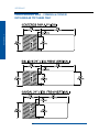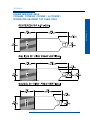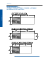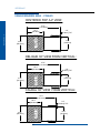
1
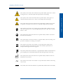
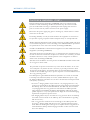
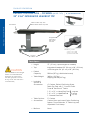
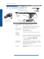
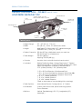
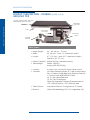
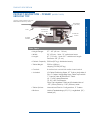
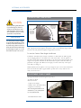
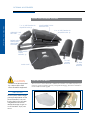
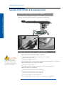
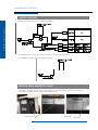
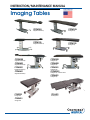
Instruction/Maintenance Manual
Imaging Tables
CFPMFXH
CFPMFXH
CFPM100
CFPM100
integrated headrest top
rectangular top
integrated headrest top
rectangular top
CFPM300
CFPM300
CFPM400
CFPM400
CFPM301
CFPM301
CFPM401
CFPMB301
integrated headrest top
integrated headrest top
integrated headrest top
integrated headrest top
rectangular top
rectangular top
rectangular top
rectangular top - Bariatric Version
CFPM401
rectangular top
CFUR301
Urology Table
CFUR401
Urology Table
CFLU401
Lithotripsy Table
© Copyright 2007
OAKWORKS®, Inc.
Notice
The information contained in this document is subject to
change without notice and should not be construed as a
commitment by Oakworks®, Inc.
Printed in U.S.A.
All rights are reserved. No part of this
document may be photocopied, reproduced
or translated to another language without prior
written consent of Oakworks®, Inc.
Oakworks® is a registered trademark of Oakworks®, Inc.
Oakworks®, Inc. assumes no responsibility for any errors
that may appear in this document nor does it make
expressed or implied warranty of any kind with regard
to this material, including, but not limited to, the
implied warranties of merchantability and fitness for a
particular purpose.
Oakworks®, Inc. shall not be liable for incidental or
consequential damages in connection with or arising
out of the furnishing, performance, or use of this
document and the program material which it describes.
table of contents
Symbol Identification .............................................................................................................. 1
Indications & Contraindications ......................................................................................... 2
Section I: Product Description & Photo
CFPMFXH Integrated Headrest & Rectangular Top............................................... 4
CFPM100 Integrated Headrest & Rectangular Top................................................. 5
CFPM300 Integrated Headrest & Rectangular Top................................................. 6
CFPM400 Integrated Headrest & Rectangular Top................................................. 7
CFPM301 Integrated Headrest & Rectangular Top................................................. 8
CFPMB301 Bariatric Top........................................................................................... 9
CFPM401 Integrated Headrest & Rectangular Top................................................10
CFLU401 Lithotripsy Top.........................................................................................11
CFUR301 Urology Top..............................................................................................12
CFUR401 Urology Top..............................................................................................13
Section II: Directions for Use
Foot Controls................................................................................................................................. 14
Hand Controls................................................................................................................................ 15
Bubble Levels, Angle Indicator & Patient Positioning Strap............................................... 16
Adjusting Table Top Pad ......................................................................................................... 17
Adjusting Cranial Positioning Pads (integrated headrest only)............................................. 17
Moving the Imaging Table ......................................................................................................... 18
Emergency Stop .......................................................................................................................... 18
Weight Capacity & Patient Use.................................................................................................. 19
Urology Table Bag Hoop .......................................................................................................... 20
Lithotripsy/Urology & Urology Table End Extensions....................................................... 21
Lithotripsy/Urology Table Lateral Extensions........................................................................ 22
Lithotripsy Table used as Urology Table.................................................................................. 23
Urology Table Lateral Extensions.............................................................................................. 24
Section III: Reference - Usable Imaging Area Diagrams
CFPMFXH & CFPM100 - integrated headrest tops............................................................. 25
CFPMFXH & CFPM100 - rectangular tops........................................................................... 26
CFPM400,CFPM300, CFPM401 & CFPM301
- integrated headrest tops............................................................................................................. 27
CFPM400,CFPM300, CFPM401, CFPM301 & CFPMB301
- rectangular tops........................................................................................................................... 28
CFUR301 & CFUR401 - Urology top...................................................................................... 29
CFLU401 - Lithotripsy/Urology top........................................................................................ 30
Section IV: Optional Accessories
Carbon Fiber Arm Board ........................................................................................................... 31
Adjustable T-Rail Clamp ............................................................................................................ 31
Spine Positioning System ............................................................................................................ 32
Fluoro Extender .......................................................................................................................... 32
table of contents
Warnings & Precautions ...................................................................................................... 2-3
table of contents
table of contents
Section V: Maintenance & Service
Cleaning...................................................................................................................... 33
Inspection & Maintenance........................................................................................ 33
Ground Point Testing............................................................................................... 34
Troubleshooting................................................................................................34 & 35
Foot and Hand Control Replacement..................................................................... 35
Warranty Information............................................................................................... 36
Parts Identification...........................................................................................36 & 37
Wiring Diagram.......................................................................................................... 38
Model & Serial Number Location............................................................................ 38
Model Number Chart................................................................................................ 39
Specifications
Product & Electrical Specifications.. .......................................................40
Guidance & Manufacturers Declaration - Emissions (all systems)............... 41
Recommended Separations - Distances from the CFPM400 ....................... 41
Guidance & Manufacturers Declaration - Immunity .................................... 42
Guidance & Manufacturers Declaration - Emmissions
(Equipment that is NOT life supporting) ..................................................... 43
Contact Information
...................................................................... Back Cover
Symbol Identification
This symbol, when used in this manual and on product labels, represents a caution
warning. Be sure to read and comply with all precautions and warnings.
symbol identification
This symbol, when used in this manual and on product labels, warns against an
electrical shock hazard. Be sure to observe and comply with all warnings.
This symbol, when used in this manual and on product labels, indicates the potential
of exposure to harmful x-rays. Be sure to read and comply with all warnings.
This symbol, when used in this manual and on product labels, indicates that the
table and components are a Type B Applied Part pursuant to IEC 601.1 and EN
60601-1: 1990.
This symbol, when used in this manual or on product labels, indicates a Protective
Earth (Ground) Terminal.
R
US
C
LISTED
UL 2601-1
CSA C22.2 NO.601.1
IEC 60601-2 (2001-09)
This symbol when used in this manual or on product labels, warns that during transport there should be no stacking of containers.
R
R
US
C
LISTED
LISTED
UL 2601-1
CSA C22.2 NO.601.1
IEC 60601-2 (2001-09)
US
C
UL 2601-1
CSA C22.2 NO.601.1
IEC 60601-2 (2001-09)
This symbol, when used in this manual or on product labels, indicates that
the product should be protected from moisture. The humidity specifications for
Transport & Storage are listed on page 40.
R
US
C
LISTED
UL 2601-1
CSA C22.2 NO.601.1
IEC 60601-2 (2001-09)
R
This symbol, when used in this manual or on product labels, indicates that information is
given regarding the recommended temperature limits during transport and storing.
US
C
LISTED
UL 2601-1
CSA C22.2 NO.601.1
IEC 60601-2 (2001-09)
This symbol, when used in this manual or on product labels, indicates the date of
manufacture of the device.
~
This symbol, when used in this manual or on product labels, indicates alternating
current (AC).
----
This symbol, when used in this manual or on product labels, indicates direct current (DC).
R
US
C
LISTED
UL 2601-1
CSA C22.2 NO.601.1
IEC 60601-2 (2001-09)
1
warnings / precautions
warnings/precautions
product description
Oakworks® Imaging Tables are radiographic tables intended for use with mobile
or compact stationary C-arm Imaging Systems. It is ideally suited for pain management imaging and therapeutic procedures. These tables are suitable to use for
diagnostic x-ray imaging and imaging during therapeutic procedures such as spinal
injections, vertebroplasty procedures and other pain management procedures. The
CFLU & CFUR Tables are designed for Lithotripsy and Urology procedures.
Contraindications
The Oakworks® Imaging Tables should not be used with Imaging systems having
intensifier screens or film cassettes larger than 12 inches (30 cm) when an oblique
angle of view is being used.
The tables are not designed for and should not be used with Magnetic Resonance
Imaging procedures.
cautions & warnings
After unpacking your Oakworks® Imaging Table, inspect it thoroughly for
damage. If you suspect a problem do not use the table and call our customer
service department at 800-916-4612.
Improper use of this device can cause injury. Be sure to read all operating
instructions prior to use.
Weight
limit (patient and accessories): Carbon Fiber Top: 340 kg / 500 lbs. distributed evenly.
Bariatric Table only: 550 kg / 750 lbs. distributed evenly.
Do not sit beyond warning line on carbon fiber top.
Lock casters when mounting and dismounting.
The table utilizes four locking casters to permit movement of the table within the imaging suite. Accidental movement of the table may occur. Lock
casters prior to accomplishing imaging of the patient.
There may be pinch points under the table top. Do not have any body part under
the top when the table is in motion.
Be certain that the table is completely lowered prior to discharging an ambulatory
patient. The patient may lose balance and fall. NOTE: The CFPMFXH is a fixed
height table. It is recommended that all patients are assisted onto the table (physical
assistance & step stools with side rails is recommended.)
Patient Safety Strap must be secured prior to using the O akworks® Imaging
Tables.
2
Warnings / precautions
Electrical Shock Hazard. (Excluding CFPMFXH) The power supply/control
module is located inside lifting column and under the top. No user serviceable
parts are inside. Refer servicing to qualified personnel. Unplug wall connector
prior to contact with any cables connected to the power supply.
Disconnect the power supply plug prior to cleaning any surfaces below or inside
of the base of the table.
Grounding reliability can only be achieved when this equipment is connected to
an equivalent 3 prong receptacle marked “Hospital Only” or “Hospital Grade”.
Medical Electrical Equipment needs special precautions regarding EMC and needs
to be installed and put into service according to the EMC information provided in
the specifications at the end of this manual. (Excluding CFPMFXH)
Portable and Mobile RF Communications Equipment can affect Medical Electrical
Equipment. (Excluding CFPMFXH)
The Table should not be used adjacent to or stacked with other equipment due to
the risk of electronic interference. If adjacent or stacked use is necessary, the table
should be observed to verify normal operation in the configuration in which it
will be used. (Excluding CFPMFXH)
This table is not suitable for use in the presence of flammable anesthetic mixture with
air or oxygen or nitrous oxide.
The potential of exposure to harmful x-rays exists when this table is in use. The
use of adequate x-ray barrier devices is necessary to provide protection to both
the operator and the patient. X-ray barrier devices are recommended for the patient
outside of the intended target area to prevent exposure to scattered radiation from
the x-ray generating source.
The tabletop has a typical aluminum filtration equivalence of 1.10 mm as measured
at 100 kVp and a half value (HVL) of 3.6 mm. (NOTE: Bariatric Top has a typical aluminum filtration equivalence of 1.50 mm. as measured at 100 kVp and a half
value (HVL) of 3.6 mm.)
• Oakworks® Imaging Tables may be used for x-ray imaging where the x-ray generator is located below the tabletop and the image receptor is located above the tabletop. This is the recommended method. The tables may also be used for x-ray imaging where the x-ray generator is located above the tabletop and the image receptor is located below the tabletop. This application will result in greater patient exposure to x-rays. The operator must weigh this issue with the imaging requirements and patient exposure issues.
• The Imaging Tables may be used with the x-ray generator above the tabletop and a film cassette located on the tabletop. (See contraindications regarding film cassette size.)
• The x-ray generator should never be located above the tabletop when the Oakworks® Imaging Table and the Oakworks® Spine Positioning System/
Prone Pillow are used together. This type of use requires that the x-ray generator is located below the tabletop and the imaging intensifier or film cassette located above the tabletop.
3
warnings/precautions
cautions & warnings: (cont.)
product description
product Description - CFPMFXH (model: flfd)
22” x 84” integrated headrest top
24” x 80” rectangular top
Carbon Fiber Top with
Removable Table Top Pad
product description
Hand Rail
Integrated
Face Rest
with Face
Cushion
1)
2)
3)
Includes 3-pad Set:
1) 2” h x 12” s q Pad
2) 4” h x 12” s q Pad
3) Crescent Face Pad
Locking
Casters
Table Specs :
caution
• Height:
• Top:
37” (91 cm) (optional heights are available)
Integrated Headrest 22” (56 cm) x 84” (214 cm)
or Rectangular 24” (61 cm) x 80” (203 cm)
• Patient
The CFPMFXH is a fixed height
Capacity:
500 lbs.(227 kg.) distributed evenly
table. It is recommended that
all patients are assisted onto • Table Weight:
368 lbs. (167 kg.)
the table (physical assistance shipping 500 lbs.(227 kg.)
& step stools with side rails is
• Included
recommended.)
options &
Accessories:
4” Casters, Patient Positioning Strap,
Table Top Pad with 1” Comfort Foam
Foam & TerraTouch™ Fabric
}
1- 2”h x 12” sq Head Rest Pad
1- 4”h x 12” sq Head Rest Pad
1 - Crescent Face Pad
5” Casters
• Table Options:
Integrated
Headrest
Top Only
• Accessories:
Carbon fiber arm board, Spine Positioning
System, Fluoro-Extender, 2” Table top pad,
Adjustable T-rail clamp
None
• Motions:
4
Product description
product description - CFPM100 (model: fl10)
22” x 84” integrated headrest top
24” x 80” rectangular top
Carbon Fiber Top with
Removable Table Top Pad
product description
Hand Rail
1)
Electronic
Lift Tower
2)
3)
Includes 3-pad Set:
1) 2” h x 12” s q Pad
2) 4” h x 12” s q Pad
3) Crescent Face Pad
Integrated
Face Rest
with Face
Cushion
Power kill
switch
Locking
Casters
Table Specs :
•Height Range:
22” - 40” (56 cm - 102 cm)
•Top:
Integrated Headrest 22” (56 cm) x 84” (214 cm)
or Rectangular 24” (61 cm) x 80” (203 cm)
•Patient
Capacity:
500 lbs.(227 kg.) distributed evenly
•Table Weight:
343 lbs. (146 kg.)
shipping 475 lbs.(215 kg.)
1 foot control
•Controls:
• Included
options &
Accessories:
4” Casters, Patient Positioning Strap, Table Top Pad
with 1”Comfort Foam & TerraTouch™ Fabric
1- 2”h x 12” sq Head Rest Pad
1 - 4”h x 12” sq Head Rest Pad
1 - Crescent Face Pad
International Electric Configurations, 5” Casters
•Table Options:
}
Integrated
Headrest
Top Only
•Accessories:
Carbon fiber arm board, Spine Positioning System,
Fluoro-Extender, 2” Table top pad,
Adjustable T-rail clamp
Vertical Motion
•Motions:
5
product description
product description - CFPM300 (model: fl30)
22” x 84” integrated headrest top
24” x 80” rectangular top
product description
Carbon Fiber Top with
Removable Table Top Pad
1)
Integrated
Face Rest
with Face
Cushion
2)
3)
Includes 3-pad Set:
1) 2” h x 12” s q Pad
2) 4” h x 12” s q Pad
3) Crescent Face Pad
Electronic
Lift Tower
Hand Rail
Power kill
switch
Locking
Casters
Table Specs :
•Height Range:
•Top:
26” - 44” (66 cm - 112 cm)
Integrated Headrest 22” (56 cm) x 84” (214 cm)
or Rectangular 24” (61 cm) x 80” (203 cm)
•Patient Capacity: 500 lbs.(227 kg.) distributed evenly
•Table Weight:
498 lbs. (226 kg.)
shipping 630 lbs.(286 kg.)
3 motion foot control & 3 motion hand control
•Controls:
• Included
options &
Accessories:
Patient Positioning Strap, 4” Casters, Table Top
Pad with 1” Comfort Foam & TerraTouch™ Fabric
1- 2”h x 12” sq Head Rest Pad
1 - 4”h x 12” sq Head Rest Pad
1 - Crescent Face Pad
International Electric Configurations, 5” Casters
•Table Options:
}
Integrated
Headrest
Top Only
•Accessories:
Carbon fiber arm board, Spine Positioning System,
Fluoro-Extender, 2” Table top pad,
Adjustable T-rail clamp
Vertical, Trendelenburg (+15°/-12°), Lateral Tilt (±15°)
•Motions:
6
product description
product description - CFPM400 (model: fl40)
22” x 84” integrated headrest top
24” x 80” rectangular top
1)
Integrated
Face Rest
with Face
Cushion
2)
3)
Includes 3-pad Set:
1) 2” h x 12” s q Pad
2) 4” h x 12” s q Pad
3) Crescent Face Pad
Electronic
Lift Tower
Hand Rail
Power kill
switch
Locking
Casters
Table Specs :
•Height Range:
•Top:
26” - 44” (66 cm - 112 cm)
Integrated Headrest 22” (56 cm) x 84” (214 cm)
or Rectangular 24” (61 cm) x 80” (203 cm)
•Patient Capacity: 500 lbs.(227 kg.) distributed evenly
•Table Weight:
498 lbs. (226 kg.)
shipping 630 lbs.(286 kg.)
4 motion foot control & 4 motion hand control
•Controls:
• Included
options &
Accessories:
Patient Positioning Strap, 4” Casters, Table Top
Pad with 1” Comfort Foam & TerraTouch™ Fabric
1- 2”h x 12” sq Head Rest Pad
1 - 4”h x 12” sq Head Rest Pad
1 - Crescent Face Pad
International Electric Configurations, 5” Casters
•Table Options:
}
Integrated
Headrest
Top Only
•Accessories:
Carbon fiber arm board, Spine Positioning System,
Fluoro-Extender, 2” Table top pad,
Adjustable T-rail clamp
•Motions:
Vertical, Trendelenburg (+15°/-12°), Lateral Tilt (±15°),
Longitudinal (10”)
7
product description
Carbon Fiber Top with
Removable Table Top Pad
product description
product description - CFPM301 (model: fl31)
22” x 84” integrated headrest top
24” x 80” rectangular top
product description
Carbon Fiber Top with
Removable Table Top Pad
1)
Integrated
Face Rest
with Face
Cushion
2)
3)
Includes 3-pad Set:
1) 2” h x 12” s q Pad
2) 4” h x 12” s q Pad
3) Crescent Face Pad
Electronic
Lift Tower
Hand Rail
Power kill
switch
Locking
Casters
Table Specs :
•Height Range:
•Top:
25” - 43” (64 cm - 109 cm)
Integrated Headrest 22” (56 cm) x 84” (214 cm)
or Rectangular 24” (61 cm) x 80” (203 cm)
•Patient Capacity: 500 lbs.(227 kg.) distributed evenly
•Table Weight:
538 lbs. (244 kg.)
shipping 670 lbs.(304 kg.)
3 motion foot control & 3 motion hand control
•Controls:
• Included
options &
Accessories:
Patient Positioning Strap, 4” Casters, Table Top
Pad with 1” Comfort Foam & TerraTouch™ Fabric
1- 2”h x 12” sq Head Rest Pad
1 - 4”h x 12” sq Head Rest Pad
1 - Crescent Face Pad
International Electric Configurations, 5” Casters
•Table Options:
}
Integrated
Headrest
Top Only
•Accessories:
Carbon fiber arm board, Spine Positioning System,
Fluoro-Extender, 2” Table top pad
Adjustable T-rail clamp
Vertical, Trendelenburg (+15°/-11°), Longitudinal (10”)
•Motions:
8
product description
(model: flbaba)
Carbon Fiber Top with
Removable Table Top Pad
Hand Rail
product description
product description - CFPMb301
24” x 80” bariatric top
Electronic
Lift Tower
Power kill
switch
Locking
Casters
Table Specs :
• Height Range:
26” - 44” (66 cm - 112 cm)
•Top:
24” (56 cm) x 80” (203 cm)
•Patient Capacity: 750 lbs.(340 kg.) distributed evenly
•Table Weight:
573 lbs. (260 kg.)
shipping 705 lbs.(320 kg.)
3 motion foot control & 3 motion hand control
•Controls:
• Included
options &
Accessories:
Patient Positioning Strap, 5” Casters, Table Top
Pad with 1” Comfort Foam & TerraTouch™ Fabric
International Electric Configurations
•Table Options:
•Accessories:
Carbon fiber arm board, Spine Positioning System,
Fluoro-Extender, 2” Table top pad
Vertical, Trendelenburg (+15°/-11°), Longitudinal (10”)
•Motions:
9
product description
product description - CFPM401 (model: fl41)
22” x 84” integrated headrest top
24” x 80” rectangular top
product description
Carbon Fiber Top with
Removable Table Top Pad
1)
Integrated
Face Rest
with Face
Cushion
2)
3)
Includes 3-pad Set:
1) 2” h x 12” s q Pad
2) 4” h x 12” s q Pad
3) Crescent Face Pad
Electronic
Lift Tower
Hand Rail
Power kill
switch
Locking
Casters
Table Specs :
•Height Range:
•Top:
26” - 44” (66 cm - 112 cm)
Integrated Headrest 22” (56 cm) x 84” (214 cm)
or Rectangular 24” (61 cm) x 80” (203 cm)
•Patient Capacity: 500 lbs.(227 kg.) distributed evenly
•Table Weight:
548 lbs. (249 kg.)
shipping 680 lbs.(308 kg.)
4 motion foot control & 4 motion hand control
•Controls:
• Included
options &
Accessories:
Patient Positioning Strap, 4” Casters, Table Top
Pad with 1” Comfort Foam & TerraTouch™ Fabric
1- 2”h x 12” sq Head Rest Pad
1 - 4”h x 12” sq Head Rest Pad
1 - Crescent Face Pad
International Electric Configurations, 5” Casters
•Table Options:
}
Integrated
Headrest
Top Only
•Accessories:
Carbon fiber arm board, Spine Positioning System,
Fluoro-Extender, 2” Table top pad,
Adjustable T-rail clamp
•Motions:
Vertical, Trendelenburg (+15°/-11°), Longitudinal (10”)
Lateral (±4”)
10
product description
T-rail
(model: fl41li)
End Extension
Carbon Fiber Top with
Removable Table Top Pad
(along each side)
L a te r a
l
io n s
E x te n s
Hand Rail
(4)
(under end)
product description
product description - CFlu401
lithotripsy/urology top
End Extension
Power kill
switch
Locking
Casters
Table Specs :
•Height Range:
27” - 45” (69 cm - 114 cm)
•Width:
23” (58 cm) - Note: 19” radiolucent width
• Length:
Main Table: 47” (119cm) Note: 23.7” radiolucent length
Extensions: 28” (71cm), 16” (41cm)
•Patient Capacity: 500 lbs.(227 kg.) distributed evenly on main top
200 lbs.(91 kg.) on all extensions
•Table Weight:
618 lbs. (280 kg.)
shipping 750 lbs.(340 kg.)
4 motion foot control & 4 motion hand control
•Controls:
• Included:
Patient Positioning Strap, Urology Bag Hoop, 5” Casters,
Table Top Pad with 1” Comfort Foam & TerraTouch™ Fabric
Note: The Integrated T-Rails are US standard size of
.375” (9.5mm) thick by 1.125” (28.6mm) wide.
International Electric Configurations , 4” Casters
•Table Options:
1- 23” x 28” End Extension (Cantilevered End)
1- 23” x 16” Short End Extension (Support Tower End) OR
23” x 20” Short End Extension (Support Tower End)
2 - 8” x 11” Lateral Extensions
1 - 8” x 14” Lateral Extension
1 - 8” x 24” Lateral Extension
T-Rails on both sides of top (excluding Litho openings)
•Accessories:
Carbon fiber arm board, Spine Positioning System,
Fluoro-Extender
•Motions:
Vertical, Trendelenburg (+15°/-11°), Longitudinal (10”)
Lateral (±4”)
11
product description
product description - CFur301
urology top
(model: fl31ur)
product description
Urology Carbon Fiber Top with
Removable Table Top Pad
T-rail
Hand Rail
(at end)
Electronic
Lift Tower
Power kill
switch
Locking
Casters
Table Specs :
• Height Range:
26” - 44” (66 cm - 112 cm)
•Width:
23” (58 cm) - Note: 19” radiolucent width
•Length:
47” (119 cm) - Note: 23.7” radiolucent length
Extension: 28” (71 cm)
•Patient Capacity: 500 lbs.(227 kg.) distributed evenly
•Table Weight:
568 lbs. (258 kg.)
shipping 700 lbs.(318 kg.)
3 motion foot control & 3 motion hand control
•Controls:
• Included:
(2) Patient Positioning Straps, 47” T-rails on both sides of
top, 4” Casters, Urology Bag Hoop, Table Top Pad with
1” Comfort Foam & TerraTouch™ Fabric
(2) - 5”x 24” Lateral Extensions
(1)- 23” x 28” End Extension
Note: The Integrated T-Rails are US standard size of
.375” (9.5mm) thick by 1.125” (28.6mm) wide.
•Table Options:
International Electric Configurations, 5” Casters
•Motions:
Vertical, Trendelenburg (+15°/-11°), Longitudinal (10”)
12
product description
product description - CFur401
urology top
(model: fl41ur)
Urology Carbon Fiber Top with
Removable Table Top Pad
Electronic
Lift Tower
Power kill
switch
Locking
Casters
product description
T-rail
Hand Rail
(at end)
Table Specs :
• Height Range:
27” - 45” (69 cm - 114 cm)
•Width:
23” (58 cm) - Note: 19” radiolucent area
•Length:
47” (119 cm) - Note: 23.7” radiolucent length
Extension: 28” (71 cm)
•Patient Capacity: 500 lbs.(227 kg.) distributed evenly
•Table Weight:
590 lbs. (268 kg.)
shipping 722 lbs.(327 kg.)
4 motion foot control & 4 motion hand control
•Controls:
• Included:
(2) Patient Positioning Straps, 47” T-rails on both sides of
top, 4” Casters, Urology Bag Hoop, Table Top Pad with
1” Comfort Foam & TerraTouch™ Fabric
(2) - 5”x 24” Lateral Extensions
(1)- 23” x 28” End Extension
Note: The Integrated T-Rails are US standard size of
.375” (9.5mm) thick by 1.125” (28.6mm) wide.
•Table Options:
International Electric Configurations, 5” Casters
•Motions:
Vertical, Trendelenburg (+15°/-11°), Longitudinal (10”)
Lateral (±4”)
13
directions for use
directions for use - foot controls
one motion
directions for use
Used to raise and lower height of the table.
3 motion
Used to control table Vertical Height, Trendelenburg, Lateral Tilt OR
Vertical Height, Trendelenburg, Longitudinal Motion.
Control functions dependent
upon table’s features.
4 motion
Used to control table Vertical Height, Trendelenburg, Longitudinal Motion,
Lateral Tilt OR Vertical Height, Trendelenburg, Longitudinal Motion, Lateral Motion.
Control functions dependent
upon table’s features.
14
directions for use
directions for use hand controls
3 motion
directions for use
Used to control table Vertical Height, Trendelenburg, Lateral Tilt OR
Vertical Height, Trendelenburg, Longitudinal Motion.
Control functions dependent
upon table’s features.
4 motion
Used to control table Vertical Height, Trendelenburg, Longitudinal Motion,
Lateral Tilt OR Vertical Height, Trendelenburg, Longitudinal Motion, Lateral Motion.
Control functions dependent
upon table’s features.
15
directions for use
Bubble levels
directions for use
Bubble levels are installed on the handle end of the table to aid the operator
to determine the horizontal plane.
angle indicator
Standard on CFLU401 and CFUR301 Tables.
Optional on all other Imaging Tables.
To use angle indicator, simply press “on/off”
button on the left side of the indicator.
NOTE: Do not press “zero” unless table
is in the horizontal position.
Patient Positioning Strap
caution
Patient Safety Strap must
be secured.
The Patient Positioning strap must be used during all procedures to prevent
the patient from falling off the table. The strap has Velcro® attached to the ends.
Strap is attached as follows:
1. Place the center of the strap around the patient’s waist. Relocate the strap as
necessary for adequate clearance.
2. Take the ends of the strap down around the
table top. Pull the strap snug underneath the
table and press the two Velcro® ends together.
3. Check the strap to assure adequate patient
restraint prior to the Trendelenburg motion.
16
directions for use
Removal
ofthe
Table
Pad
accessory)
adjusting
table
top(optional
pad
directions for use
Underside of Tabletop
caution
There may be pinch points under
the table. Do not have any body
part under the table when the
table is in motion.
Remove Table Pad by pulling flaps at the underside of the table on either end
until the hook and loop fastener becomes unanchored.
Replace pad by first centering on the table and then pressing flaps in place,
anchoring with the hook and loop fasteners.
adjusting the Cranial Positioning Pads Integrated headrest
Face Resttables
Pad Configurations
integrated
only
Prone Positioning: Use the Crescent Face Pad and adjust accordingly.
Pads are held in place by
hook & loop fasteners.
The Crescent Face Pad can
be adjusted as needed.
Place close in to the edge
of the table with sides
together for smaller patients
or further away from the
edge with sides apart for
larger patients.
Supine Positioning: Use either the 2” or 4” square pad for proper placement.
2” or 4”
Pads are provided that give
two levels of elevation:
2” or 4”
Pads attach to the integrated face rest
extension with hook & loop fasteners that
hold the pad securely in place.
17
directions for use
Moving Imaging Table
directions for use
Be sure to lower table completely before attempting to move it.
NOTE
Casters are designed
for normal Hospital/
Clinic environments. Not
intended for outdoor
travel/use.
Unlocked Caster - Table may be moved
Push down until locking lever clicks into place.
Unlocked caster.
Locked Caster - Table locked down.
Emergency Stop
All electric tables are equipped with an emergency stop switch. To stop the operation, push the red button. To reset, rotate the red button clockwise.
18
directions for use
weight capacity & patient use
directions for use
The Oakworks® table top is rated at 500 lb. load evenly distributed. (Bariatric
table is rated at 750 lbs.) To minimize any risk to the patient, do not allow the
patient to sit on the face rest area beyond the warning line on the table top.
do not sit beyond this point.
safe zone
Casters should be locked when patient is mounting or dismounting the table.
Table should be flat when mounting and dismounting.
Patient should mount and dismount near the lifting column.
Table top should be moved fully to the rear after each use.
19
directions for use
urology table bag hoop
directions for use
Slide bag over Urology hoop.
Attach ends of hoop to the ends of the table T-rails. Tighten hoop ends to the T-rail.
Completed assembly.
20
directions for use
end extensions - Urology & lithotripsy/urology top
To insert extension, simply slide the two “arms” into the ends of the table top. Push fully
in. Extension arms will drop slightly into a locking pin.
To remove extension, simply lift extension slightly and pull away from table top.
21
directions for use
There are extensions which can be inserted on either end of the table.
(1) - 23” x 28” and (1) - 23” x 16” - Lithotripsy/Urology, (1) - 23” x 28” - Urology
directions for use
directions for use
lateral extensions - lithotripsy/urology top
There are four lateral extensions for the Lithotripsy table. (2 - 8” x 11”,
1 - 8” x 14” and 1 - 8” x 24”). The 8” x 24” extension is designed to bridge
the Lithotripsy opening.
8” x 11”
8” x 24”
8” x 14”
8” x 11”
The 2 - 8” x 11” are angled and designed to be used on both
sides of the Lithotripsy opening.
The 8” x 14” extension can be used as required for your procedure along with
other extensions.
22
directions for use
lateral extensions (cont.)
directions for use
The Lateral Extensions are clamped to the T-rail with a locking clamp design.
lithotripsy table used as a urology table
If the extensions are removed from the Lithotripsy Table, the table can be used as a
Urology Table. A bag hoop is included with your table. (Refer to Urology Table Bag
Hoop directions for use).
23
directions for use
lateral extensions - urology top
directions for use
There are 2 lateral extensions for the Urology Table - (2) 5” x 24”. These extensions can be used as required to extend the effective width of the table top.
24
Reference
reference
Usable imaging area - CFPMFXH & CFPM100 Integrated head
rest top tables only
25
Reference
reference
Usable imaging area - CFPMFXH & CFPM100
rectangular top tables only
26
Reference
reference
Usable imaging area
CFPM400, CFPM300, CFPM401, & CFPM301
Integrated Headrest top Table only
27
reference
reference
Usable imaging area
CFPM400, CFPM300, CFPM401, CFPM301 & CFPMB301
rectangular top table only
28
Reference
Usable imaging area - CFur301 & CFUR401
CENTERED FOP A-P VIEW:
47.0"
[119.38cm]
23.3"
[59.06cm]
reference
No Image
23.0"
[58.42cm]
2.0"
[5.08cm] TYP
19.0"
[48.26cm]
OBLIQUE 30° VIEW FROM VERTICAL:
47.0"
[119.38cm]
23.3"
[59.06cm]
No Image
21.0"
[53.34cm]
2.8"
[6.99cm] TYP
15.5"
[39.37cm]
CAUDAL 30° VIEW FROM VERTICAL:
41.5"
[105.41cm]
20.0"
[50.80cm]
No Image
23.0"
[58.42cm]
2.0"
[5.08cm] TYP
19.0"
[48.26cm]
29
Reference
Usable imaging area - CFlu401
CENTERED FOP A-P VIEW:
47.0"
[119.38cm]
2.0"
[5.08cm] TYP
No Image
reference
23.3"
[59.06cm]
23.0"
[58.42cm]
19.0"
[48.26cm]
OBLIQUE 30° VIEW FROM VERTICAL:
47.0"
[119.38cm]
23.3"
[59.06cm]
No Image
21.0"
[53.34cm]
2.8"
[6.99cm] TYP
15.5"
[39.37cm]
CAUDAL 30° VIEW FROM VERTICAL:
41.5"
[105.41cm]
20.0"
[50.80cm]
No Image
23.0"
[58.42cm]
30
2.0"
[5.08cm] TYP
19.0"
[48.26cm]
optional accessories
Carbon Fiber Arm Board
When making adjustments
in positioning be sure to
observe all cautions and
warnings given in the manual to prevent injury to both
opetator and patient.
Carbon Fiber
Arm Board
base slides
under table
top pad
Upper Arm
Board rotates
as needed
a full 180º
Prone Position at 135º
IMPORTANT
DO NOT place undue weight
or downward pressure on the
Carbon Fiber Arm Board. It is
a positioning device for the
arms and should not be used
as leverage to get on or off
the table. Injury can occur.
to 180º
Supine Position at 180º
The Oakworks® Carbon Fiber Single Arm Board conveniently slides under the
table top pad and easily supports the patient’s arm in a positionary range of 180º.
The unit can easily fold for compact storage when not in use.
To use the Carbon Fiber Single Arm Board:
Unfold the Arm Board just enough to enable it to slide under the table top pad
on the Imaging Table at a 90º angle to the side of the table. Ask the patient to
lie down on the table. Position the patient to suit the needs of the procedure. The
weight of the patient will hold the Arm Board base in place under the table top
pad. Move the upper Arm Board to the angle you need. It will stay at that position until you change it.
When finished, ask the patient to rise up enough for you to move the Arm Board
base from under the table top pad. Fold it up and store it away until the next
time you need to use it.
adjustable t-rail clamp
(Intergrated Headrest & Rectangular Tops Only*)
To attach or adjust
table accessories:
1. Open T-rail clamp.
2. Slide T-rail to desired location.
3. Tighten T-rail clamp.
Note: The Integrated T-Rails are US
standard size of .375” (9.5mm) thick
by 1.125” (28.6mm) wide.
*Excludes Bariatric table
31
optional accessories
caution
optional accessories
optional accessories
Spine positioning system
7” x 12” rectangular
adjuster pads (2)
Contoured Torso
Support Pad
8” x 16” rectangular
adjuster pads (2)
Crescent Face
Rest Pad
Radiolucent
frame with
adjustable
face rest
Contoured
Torso
Wedges (2)
8” half
round
bolster
carry case
caution
8” semi
round
bolster
Fluoro Extender
The Oakworks® Fluoro Extender is radiolucent and offers extra width only where you
need it for greater positioning accuracy with optimum imaging. The Fluoro Extender is
inserted under the table top pad.
Children must be supervised
by a responsible adult
when around this equipment.
IMPORTANT
DO NOT place undue weight
or downward pressure on the
Fluoro Extender. It is a positioning device for the arms
or legs and should not be
used as leverage to get on
or off the table. Injury can
occur.
32
maintenance & service
IMPORTANT
caution
Before cleaning with any
liquid cleaner be sure to
unplug the power cord
from the power outlet.
Table
Use only a mild detergent solution or 10% sodium hypochlorite solution on surfaces.
Be sure excess liquid does not drip onto any other surfaces or mechanisms.
Disinfectants other than recommended above will harm the table’s surface. Wipe off
excess with a lint-free cloth. Remove residual with a damp (not wet) cloth.
Table Pad
Clean your upholstered items when needed using a mild solution of 4:1 diluted nonalcohol cleaner such as Formula 409®, Fantastik®, Green Windex® or some other
non-abrasive cleaner. For disinfecting purposes you may use Protex, MadaCide, Accell
TB, Virox® (Canada) or a diluted 1/100 bleach solution. Dry the fabric immediately
after cleaning to remove excess cleaning solution. Using citrus based cleaners or other
strong cleaners, such as alcohol, acetone, higher concentrations of bleach or other
products that contain high concentrations of these substances, can shorten the life of
your fabric. Be sure underside of table pad is completely dry prior to placing back
onto tabletop.
Note: Damage caused by cleaners will not be covered under the warranty.
The operator should ascertain the disinfecting properties of the agent being used prior
to cleaning.
inspections & Maintenance
Recommended regular inspections (monthly or local standard)
IMPORTANT
Be sure to read all cautions,
warnings and instructions
given in the manual to
prevent injury to both
operator and client.
• Check for damage to the power, handset or footswitch cables.
• Visually inspect components for obvious damage that could cause problems
during operation.
Recommended periodic inspections (yearly or local standard)
• Check for damage to the power, handset or footswitch cables and all visible
wiring.
• Visually inspect components for obvious damage that could cause problems
during operation.
• Check all mechanical functions using the foot control. Repeat using the
hand control. Check for abnormal noises.
• Replace any missing or illegible labels.
• Check that all fasteners are present and fastened securely.
• Check table grounding. (See Ground Point Testing)
• Clean unusual buildup of dirt on the table and/or parts of the table not
normally cleaned on a regular basis.
• Check for tears or cracks in the tabletop pads.
maintenance
• The angle indicator (present on some tables) uses a battery for power. This battery
will need to be replaced periodically (recommended yearly). To replace the battery,
remove the angle indicator from the table (it is held on with Velcro®). Unscrew the
back cover, replace battery (#CR2023), replace cover. Reattach angle indicator on
table, push “on/off” button on the left, move table top to a horizontal position,
then hit “zero” button on the right.
NOTE: The electronics and motions do not require any general maintenance
or lubrication.
33
maintenance & service
Cleaning
maintenance & service
ground point testing & troubleshooting
Ground point testing (electric tables)
maintenance & service
To confirm table grounding from the plug to the metal table, use the ground post
located on the base. (Connect the tester to the ground post and the plug.)
If the table top will not change position
Table will not function in any capacity:
caution
The Carbon Fiber table
weighs as much as 475 lbs
(216 kg). Turning the table
on its side is not required
and not recommended.
• Check to make sure the Emergency Stop Button is not engaged.
(Must be in the up position).
• Check Power Supply in the room.
• If the table still fails to operate, contact our customer service department. 717.235.6807
Table Height will not raise or lower:
• Check foot pedal connection.
• If the table still fails to operate, contact our customer service department.
Table Top will not operate:
• Check hand control connection to the control box.
• Check actuator(s) connection to the control box.
• Check power cord connection to the control box.
• Is there a green light lit on the control box?
• If the table still fails to operate, contact our customer service department.
34
maintenance & service
troubleshooting
1. If angle indicator will not work, the battery may need to be replaced.
(See maintenance instructions)
2. If the angle indicator on the table does not read near “0.0” in the
horizontal position, the indicator may need to be reset. To reset the level
indicator, just push the right “zero” button on the indicator.
maintenance & service
Angle indicator does not work or is inaccurate (if applicable)
FOOT control Replacement instructions electric tables
Replacement of the foot control will be necessary if the foot control does not
activate the correct function.
To Replace the foot control, follow these steps:
1. Before proceeding, disconnect the power cord from the power outlet.
2. Follow foot control cord back to the nearest junction connector (remove
cable guides and strain relief as required). Disconnect foot control.
4. Plug the power cord back into the power outlet.
5. Attempt to operate the table functions from the Foot Control.
6. If the table functions fail to operate, contact the Customer Service Department.
3. Obtain the new foot control and insert the cable plug into the junction
connector until firmly seated. Reconnect strain relief and cable guides.
Hand control Replacement instructions electric Tables (if applicable)
Replacement of the hand control will be necessary if the hand control does not
activate the correct table function.
To replace the hand control, follow these steps:
1. Before proceeding, disconnect the power cord from the power outlet.
2. Follow hand control cord back to the nearest junction connector (remove
cable guides and strain relief as required). Disconnect hand control.
3. Obtain the new hand control and insert the cable plug into the
junction connector until firmly seated. Reconnect cable guides and
strain relief.
4. Plug the power cord back into the power outlet.
5. Attempt to operate the table functions from the hand control.
6. If the table functions fail to operate, contact the Customer Service Department. 717.235.6807
35
maintenance & service
Warranty
maintenance & service
View complete warranty details at www.oakworks.com
All warranties are limited to factory-provided replacement parts, factory repair or
replacement, at the discretion of Oakworks®. Oakworks® only covers parts and labor
on field repair of stationary products.
All warranties exclude damage caused by improper set-up, accident, abuse, misuse,
neglect, use for other than intended purpose or reasonable wear such as tears in the
upholstery.
All warranties are invalidated by non-factory modifications and unauthorized repairs,
which will immediately terminate all liability by Oakworks® for the product or damages
caused by its use.
The buyer and its customers shall be responsible for proper set-up and use of the products as well as any supervision required for safety. In no event shall Oakworks® be liable
for any special, indirect, consequential, incidental, exemplary or punitive damages or
costs. Use of non-approved cleaning solutions voids the guarantee on all fabrics.
The warranties set forth herein are the sole and exclusive warranties provided by
Oakworks®. There are no other warranties, representations or guarantees provided by
Oakworks® either expressed or implied, including warranties of merchantability and fitness for a particular purpose. Warranty valid with proof of purchase.
parts identification - Power Cord Parts
Plug View:
Voltage (AC)
Power Cord Plug
120v 60 Hz
3 prong grounded
hospital grade; North America
220v 50 Hz
Continental Plug; Europe
220v 50 Hz
Swiss plug; Switzerland
220v 50 Hz
British plug; United Kingdom
36
maintenance & service
parts identification - table Parts
Part No.Description
maintenance & service
55848
Locking 4" Caster
65190
Locking 5" Heavy Duty Caster
64649-110
Control Box - U.S.
64649-220
Control Box - European
9723-110
Lifting Column - U.S.
9723-220
Lifting Column - European
63884-110
Lifting Column CFLU401 & CFPMB301 - U.S.
63884-220
Lifting Column CFLU401 & CFPMB301 - European
55720
Longitudinal Motion Actuator
4723
Trendelenburg Motion Actuator
64653
Tilt Motion Actuator
64682
Heavy Duty Trendelenburg Motion Actuator - CFLU401 & CFPMB301
65966
Tilt Indicator
64845
Urology bag hoop
8806
Patient Positioning Strap
53330
Single Motion Foot Control - CFPM100
64434
6 Pedal Foot Control
64431
8 Pedal Foot Control
56035
6 Button Hand Control
56035-3
6 Button Hand Control Face Overlay for CFPM301, CFPMB301 & CFUR301
56035-4
6 Button Hand Control Face Overlay for CFPM300
55721
8 Button Hand Control
55721-1
8 Button Hand Control Face Overlay - CFPM400
55721-2
8 Button Hand Control Face Overlay - CFLU401
6411-06
Table Top Pad - 1" x 23" x 47" - Urology
6408-06
Table Top Pad - 1" x 23" x 47" - Lithotripsy
58940-06
Table Top Pad - 1" x 24" x 80" - Rectangular
9468-06
Table Top Pad - 1" x 22" x 84" - Intergrated Head Rest
4796-06
Head Rest Pad - 2" x 12" x 12"
4795-06
Head Rest Pad - 4" x 12" x 12"
2410-06
Crescent Face Rest Pad
Lithotripsy/Urology Table Only
64656
Longitudinal or Lateral Motion Actuator
18051-06
Table End Extender, Large
18052-06
Table End Extender, Small
18055-06
Angled Table Side Extender, Left
18056-06
Angled Table Side Extender, Right
18053-06
Table Side Extender, Large
18054-06
Table Side Extender, Small
Optional Accessories
3395-01
Carbon Filber Arm Board
4796-06
Head Rest Pad - 2" x 12" Square
3PXXXXXXXXTTOakworks® Prone Pillow
2005Fluoro-Extender
6427-06
Table Top Pad - 2" x 22" x 84" - Intergrated Head Rest
TBD
Table Top Pad - 2" x 24" x 80" - Rectangular
63336
Clamp on T-Rail
SPSXXXXXXXTT
Spine Positioning System
37
maintenance & service
wiring diagrams
maintenance & service
1. All 400 and 401 products use the following diagram.
2. All 300 and 301 products are similar to the above, but have fewer actuators.
3. The CFPM100 product uses the following diagram.
OAKWORKS INC.
BREAK SHARP EDGES
B
1/1
model & serial Number location
The label is located on the foot end of the table at the top of the lifting column as shown below.
Exception: CFPM100 has the label located under the top.
OAK
BREAK SHARP EDGES
B
Label location
38
Model #
Serial #
1/1
maintenance & service
Diving Board Fluoroscopy Model Number Chart
model Number chart
FL 40 IF 22 26 84 MG TT XX XX
specifications
Options: - May be in any order
EU = Europe
AU = Australia
GB =United Kingdom
5C = 5" Casters
Not Used
Fabric: Terra Touch ™
Padding: Comfort
Medical Grade
Foam
Table Top Length
Minimum Table Height
Table Top Width
Top:
IF = Integrated Face Rest
RT = Rectangular
BA = Bariatric
UR = Urology
LI = Lithotripsy
Base Motion:
10 = Vertical
30 = Vertical, Trendelenberg
u & Roll
31 = Vertical, Trendelenberg
u & Longitudinal
40 = Vertical, Trendelenberg,
u Longitudinal & Roll
u Lateral & Longitudinal
41 = Vertical, Trendelenberg,
BA = Bariatric Vertical, Trendelenberg
u & Longitudinal
FD = Fixed Height
Fluoroscopy Table
39
maintenance & service
specifications
R
US
C
LISTED
UL 2601-1
CSA C22.2 NO.601.1
IEC 60601-2 (2001-09)
Temperature: 32 - 100º F 0 - 38ºC
Storage &
Transport
Humidity: 60% relative humidity
During transport, DO NOT stack containers.
Pressure: no limitations known
R
US
C
LISTED
UL 2601-1
CSA C22.2 NO.601.1
IEC 60601-2 (2001-09)
R
US
C
LISTED
UL 2601-1
CSA C22.2 NO.601.1
IEC 60601-2 (2001-09)
maintenance & service
Materials of
Construction
This product contains no latex.
This product complies with United States Department of Health and Human Services radiation performance standards,
21 CFR Subchapter J, in effect at the time of manufacture for radiographic tables.
Aluminum Filtration
Equivalent of
Table Tops
Tabletop (AL mm)
100 kVp, HVL of 3.6 mm = 1.10 (1.35 max) All Tables except Bariatric Table
100 kVp, HVL of 3.6 mm = 1.50 (1.79 max) Bariatric Table
100 kVp, HVL of 3.6 mm = 1.66 (2.00 max) All Extensions
1” TABLE TOP PAD
100 kVp, HVL of 3.6 mm = .88 (1.07 max)
2” TABLE TOP PAD
100 kVp, HVL of 3.6 mm = 1.47 (1.76 max)
ETL Classified
Complies with UL 60601-1; CSA C22.2 # 601.1, IEC 60601-2-32
Electrical specifications - CFPM100
Designed For:
North America
Europe
Input Service
120 VAC/15 amps/60Hz
230 VAC/10 amps/50Hz
Current Draw
5.8 amps
3.0 amps
Maximum Momentary Current Consumption
9.0 amps
4.5 amps
Voltage to Actuators
120 VDC
220 VDC
Class I Equipment
Class I Equipment
Electric Shock Protection
Tabletop Applied Part
Type B Applied Part
Mode of Operation
Type B Applied Part
Continuous Operation
@ 10% Duty Cycle
Electrical specifications -
Continuous Operation
@ 10% Duty Cycle
R
R
US
C
US
C
LISTED
UL 2601-1
CSA C22.2 NO.601.1
IEC 60601-2 (2001-09)
LISTED
UL 2601-1
CSA C22.2 NO.601.1
IEC 60601-2 (2001-09)
CFPM400, CFPM401, CFPM300, CFPM301, CFLU401, CFUR401, CFUR301
Designed For:
North America
Europe
Input Service
120 VAC/15 amps/60Hz
230 VAC/10 amps/50Hz
Current Draw
8.2 amps
4.5 amps
Maximum Momentary Current Consumption
12.3 amps
6.7 amps
24V Top, 120V Column
24V Top, 220V Column
Class I Equipment
Class I Equipment
Voltage to Actuators
Electric Shock Protection
Tabletop Applied Part
Type B Applied Part
Mode of Operation
40
Type B Applied Part
Continuous Operation
@ 10% Duty Cycle
Continuous Operation
@ 10% Duty Cycle
R
R
US
C
LISTED
UL 2601-1
CSA C22.2 NO.601.1
IEC 60601-2 (2001-09)
US
C
LISTED
UL 2601-1
CSA C22.2 NO.601.1
IEC 60601-2 (2001-09)
maintenance & service
specifications
All Equipment and Systems (except FLFD)
The table is intended for use in the electromagnetic environment specified below. The
customer or user of the table should ensure that it is used in such an environment.
Emissions Test
Compliance
Electromagnetic Environment - Guidance
RF Emissions
CISPR11
Class B, Group1
The tables use RF energy only for their internal function. Therefore,
the RF emissions are very low and are not likely to cause any interference in nearby electronic equipment.
Harmonics
IEC 61000-3-2
Class A
The tables are suitable for use in all establishments, including domestic, and those directly connected to the public low-voltage power
supply network that supplies buildings used for domestic purposes.
Flicker
IEC 61000-3-3
Complies
Table 206 – Recommended Separation Distances between portable and mobile RF
equipment
the CFPM400
RecommendedCommunications
Separation Distances
between and
the portable
and mobile RF
Equipment
and
Systems
that
are
NOT
Communications equipment and the OakworksLife-supporting
Imaging Tables
for Equipment and Systems that are NOT life-supporting
Recommended Separations Distances for the CFPM100
CFPM400& CFPM400
The
table
is
intended
for
use
in
the
electromagnetic
environment
in whichinradiated
disturtable
The CFPM400
is intended for use in the electromagnetic
environment
which radiated
bances are controlled. The customer or user of the table can help
prevent
electromagnetic
table
disturbances are controlled. The customer or user of the CFPM400
can help prevent
interference by maintaining a minimum distance between the portable and mobile RF
electromagnetic
by maintaining
minimum distance
portable
Communicationsinterference
Equipment and
the table as a
recommended
below,between
according
to the and
table
mobile
RF output
Communications
Equipment
and theequipment.
CFPM400
as recommended below,
maximum
power of the
communications
according to the maximum output power of the communications equipment.
Max Output Power
(Watts)
Separation (m)
150kHz to 80MHz
Separation (m)
80 to 800MHz
Separation (m)
800MHz to 2.5GHz
0.01
0.1
1
10
100
D=(3.5/V1)(Sqrt P)
.1166
.3689
1.1666
3.6893
11.6666
D=(3.5/E1)(Sqrt P)
.1166
.3689
1.1666
3.6893
11.6666
D=(7/E1)(Sqrt P)
.2333
.7378
2.3333
7.3786
23.3333
41
maintenance & service
Guidance and Manufacturer’s Declaration - Emissions
maintenance & service
specifications
maintenance & service
Table 202 – Guidance and Manufacturer’s Declaration – Immunity
All Equipment and Systems
Guidance and Manufacturer’s Declaration - Immunity
All Equipment and Systems
Guidance and Manufacturer’s Declaration – Immunity (CFPM100 & 400 only)
The CFPM400
table
is intended
for usefor
in use
the electromagnetic
environment
specified
below. below.
The
is intended
in the electromagnetic
environment
specified
table
The customer or user of the table should ensure that it is used in such an environment.
table
The customer or user of the CFPM400
should ensure that it is used in such an
environment.
Immunity Test
EN/IEC 60601
Test Level
Compliance
Level
ESD
EN/IEC 61000-4-2
±6kV Contact
±8kV Air
±6kV Contact
±8kV Air
EFT
EN/IEC 61000-4-4
±2kV Mains
±1kV I/Os
±2kV Mains
±1kV I/Os
Surge
EN/IEC 61000-4-5
±1kV Differential
±2kV Common
±1kV Differential
±2kV Common
Voltage Dips/Dropout
EN/IEC 61000-4-11
>95% Dip for
0.5 Cycle
>95% Dip for
0.5 Cycle
60% Dip for
5 Cycles
60% Dip for
5 Cycles
30% Dip for
25 Cycles
30% Dip for
25 Cycles
>95% Dip for
5 Seconds
>95% Dip for
5 Seconds
3A/m
3A/m
Power Frequency
50/60Hz
Magnetic Field
EN/IEC 61000-4-8
Report Number 3172175BOX-005
42
Electromagnetic
Environment –
Guidance
Floors should be wood,
concrete or ceramic tile.
If floors are synthetic,
the r/h should be at least
30%
Mains power quality
should be that of a
typical commercial or
hospital environment.
Mains power quality
should be that of a
typical commercial or
hospital environment.
Mainspower
power
quality
Mains
quality
should
should
that ofcommera
be
that ofbe
a typical
typical
commercial
or
cial
or hospital
environment.
hospital environment. If
If
theuser
user of the
the
thetable
requires
continued
operation
CFPM400
requires
table
during power mains interrupcontinued operation
tions, it is recommended that
during
mains
the
tablepower
be powered
from an
interruptions,power
it is supply
uninterruptible
recommended
that the
or
battery.
table
CFPM400
be powered
from an uninterruptible
power supply or battery.
Power frequency
magnetic fields should
be that of a typical
commercial or hospital
environment.
Page 41 of 44
maintenance & service
specifications
Table 204 – Guidance and Manufacturer’s Declaration – Emissions
Equipment and Systems that are NOT Life-supporting
Immunity Test
EN/IEC 60601 Test
Level
Compliance
Level
Electromagnetic
Environment –
Guidance
Portable and mobile
Portable
and mobile comcommunications
munications
equipment
equipment should
be
separated
from the from
should
be separated
the
table
CFPM400
byless
no than
less
tableby no
the
calculated/
thandistances
the distances
listed
below:
calculated/listed
below:
Conducted RF
EN/IEC 61000-4-6
3 Vrms
150 kHz to 80 MHz
(3)Vrms
D=(3.5/V1)(Sqrt P)
Radiated RF
EN/IEC 61000-4-3
3 V/m
80 MHz to 2.5 GHz
(3)V/m
D=(3.5/E1)(Sqrt P)
80 to 800 MHz
D=(7/E1)(Sqrt P)
800 MHz to 2.5 GHz
where P is the max
power in watts and D is
the recommended
separation distance in
meters.
Field strengths from
fixed transmitters, as
determined by an
electromagnetic site
survey, should be less
than the compliance
levels (V1 and E1).
Interference may occur
in the vicinity of
equipment containing a
transmitter.
Report Number 3172175BOX-005
Page 42 of 44
43
maintenance & service
Guidance and Manufacturer’s Declaration - Emissions
Equipment and
Systems–that
are NOT(CFPM100
life-supporting
& 400 only)
Guidance and Manufacturer’s
Declaration
Emissions
The CFPM400
is intended for use in the electromagnetic environment specified below.
table
The table is intended for use in the electromagnetic environment specified below. The
table
The
customer
or user
the CFPM400
should
that
it is used
in such an
customer
or user
of theoftable
should ensure
that ensure
it is used
in such
an environment.
environment.
Instruction / maintenance Manual
Imaging Tables
Contact Information:
Oakworks® Medical Equipment
923 East Wellspring Road
New Freedom, PA 17349
Phone: 717-235-6807
FAX: 717-235-6798
www.oakworksmed.com
European Authorized
Representative
Emergo Europe
Molenstraat 15
The Hague, 2513 BH Netherlands
Tel: +31 70 3458570
Fax: +31 70 3467299
Manual Part # MMMNST0008, rev. 03.27.12
5th Edition, March 2012
4th Edition, September 2009
3nd Edition, February 2009
2nd Edition, March 2008
1st Edition, October 2007
Printed in U.S.A.