1
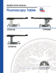
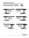
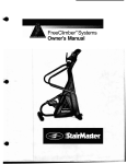
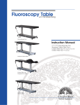
INSTRUCTION/MAINTENANCE MANUAL
PerformaLift
™
Series
Electric Salon Top
Shown with optional
Adjustable Side Arm Rests
and Universal Table Extender
Flat Top
Lift-Assist Backrest Top
Shown with optional
QuickLock™ Face rest platform
and Boiance™ crescent
www.oakworks.com · 717.235.6807
© Copyright 2012
OAKWORKS® , Inc.
Notice
The information contained in this
document is subject to change
without notice and should not
be construed as a commitment by
OAKWORKS®, Inc.
All rights are reserved. No part
of this document may be
photocopied, reproduced or
translated to another language
without prior written consent
of OAKWORKS®, Inc.
OAKWORKS® is a registered
trademark of OAKWORKS®, Inc.
OAKWORKS®, Inc. assumes no
responsibility for any errors that
may appear in this document nor
does it make expressed or implied
warranty of any kind with regard
to this material, including, but not
limited to, the implied warranties
of merchantability and fitness for
a particular purpose.
OAKWORKS®, Inc. shall not be
liable for incidental or consequential damages in connection with or
arising out of the furnishing, performance, or use of this document
and the program material which it
describes.
TABLE OF CONTENTS
TABLE OF CONTENTS
TABLE
CONTE
Symbol Identification ................................................................................................ 1
Important Safety Instructions ........................................................................... 1-2
Section I: Product Description & Photo
Electric Salon Top ....................................................................................... 3
Lift Assist Backrest Top.............................................................................. 4
Flat Top ........................................................................................................ 5
Section II: Installation
Grounding .................................................................................................. 6
Leveling ....................................................................................................... 7
Moving the Table ........................................................................................ 8
Section III: Directions for Use
Foot Control ........................................................................................... 9-10
Operating the manual backrest top ..........................................................10
Hand Control ....................................................................................... 11-12
Locking Casters ..........................................................................................13
Arm Rests ...................................................................................................14
Lowered Arm Rest .....................................................................................15
QuickLock Face Rest ..................................................................................15
Section IV: Maintenance & Service
Cleaning ......................................................................................................16
Inspection & Maintenance ........................................................................16
Troubleshooting .........................................................................................17
Foot and Hand Control Replacement ......................................................18
Parts Identification ....................................................................................19
Warranty Information ...............................................................................20
Part Number and Serial Number Location ..............................................20
Wiring Diagram .........................................................................................21
Specifications ..............................................................................................21
Guidance and manufacturer’s declaration Electromagnetic emissions ........................................................................22
Recommended separation distances ........................................................22
Guidance and manufacturer’s declaration Electromagnetic immunity .................................................................. 23-24
Contact Information ................................................................... back cover
SYMBOL IDENTIFICATION
SYMBOL
IDENTIFIC
ATION
SYMBOL IDENTIFICATION
This symbol, when used in this manual and on product labels, represents a caution
warning. Be sure to read and comply with all precautions and warnings.
This symbol, when used in this manual and on product labels, warns against an electrical
shock hazard. Be sure to observe and comply with all warnings.
This symbol, when used in this manual or on product labels, indicates a Protective
Earth (Ground) Terminal.
This symbol, when used in this manual or on product labels, indicates the date of
manufacture of the device.
~
----
This symbol, when used in this manual or on product labels, indicates alternating
current (AC).
This symbol, when used in this manual or on product labels, indicates direct current
(DC).
This symbol is used to indicate that the operator should consult the user manual.
INTRODUCTION
Oakworks PerformaLift Series offers a variety of positioning capabilities for massage
therapists and spa professionals of all specialties. On these multifunctional professional
tables the practitioner can perform numerous protocols with ease and comfort. The
fully electric PerformaLift Series is especially effective when professional protocols
require specific positioning for the client or patient. While the client receives comfortable, relaxing support, the comfort level of the therapeutic professional is enhanced by
superior ergonomics.
This table is intended to be operated by a Massage Therapist in a professional environment. No special training is required but a review of the following Safety Instructions
is important for the safety of the operator and patient. The massage professional
should read and understand this entire manual before use with a client. There are no
known contraindications to the use of this equipment.
The PerformaLift Series should not be used in any other manner than that described
within this manual. Use of any unnecessary force or unauthorized procedures could
result in injury to practitioner, client or equipment.
1
IMPORTANT SAFETY INSTRUCTIONS
READ AND
SAVE THESE
INSTRUCTIONS
CAUTION
IMPORT
T SAFE
INSTRU
ONS
IMPORTANT SAFETY INSTRUCTIONS
The PerformaLift Series Exam Table is a powered positioning table used for routine
treatment and examination procedures. It is intended to be operated by a healthcare
professional in a medical environment. No special training is required but a review of the
following Safety Instructions is important for the safety of the operator and patient. The
healthcare professional should read and understand this entire manual before use with a
patient. There are no known contraindications to the use of this equipment.
Medical Electrical Equipment needs special precautions regarding EMC and needs to be installed
and put into service according to the EMC information provided in this manual.
Portable and mobile RF communications equipment can affect Medical Electrical Equipment.
Table is not to be used as a gurney or to transport patient from room to room.
The use of accessories, transducers, and cables other than those specified by the manufacturer, may
result in increased emissions or decreased immunity of the PerformaLift Series Exam Table.
The PerformaLift Series Exam Table should not be used adjacent to or stacked with other equipment and that if adjacent or stacked use is necessary, the PerformaLift Series Exam Table should be
observed to verify normal operation in the configuration in which it will be used.
The PerformaLift Series Exam Table is designed to be a stand-alone table. This table must
not be modified or incorporated into any other equipment.
As with any moving mechanism there are potential pinch points around and underneath
the table. It is the responsibility of the operator of this equipment to insure that bystanders are not in the area below or around this equipment during operation.
Proper operation of this equipment is very important for the safety of the operator, patient,
and any other individuals in the area of this equipment. Directions for use of this
equipment are described on pages 9 through 15. The operator should read these sections carefully.
Weight Limit: (patient and accessories) 550 lbs. (250 kg) Do not exceed.
Be certain that the table is completely lowered without any tilt being present prior to
discharging an ambulatory patient. The patient may lose balance and fall.
This table is not suitable for use in the presence of flammable anesthetic mixture with air or
oxygen or nitrous oxide.
Do not operate where aerosol (spray) products are being used or where oxygen
is being administered.
Do not lift table by the table top. This can damage the table.
When lowering the table or using the Trendelenburg/Reverse Trendelenburg function, make
sure there is nothing underneath the table top that can impede motion (like stools, cabinets,
accessory parts, cleaners, etc)
Use this furnishing only for its intended use as described in these instructions. Do not use
attachments not recommended by the manufacturer.
Close supervision is necessary when this furnishing is used by, or near children, invalids,
or disabled persons.
WARNING
To reduce the risk of burns, fire, electric shock or injury to persons:
1. Unplug this furnishing from the electrical outlet before cleaning.
2. Unplug from outlet before adding or removing parts.
3. Never operate this furnishing if it has a damaged cord or plug, if it is not working
properly, if it has been dropped or damaged, or dropped into water. Contact
Oakworks Customer Service before use at 717.235.6807.
4. Keep the cord away from heated surfaces.
5. Never drop or insert any object into any opening.
6. Do not use outdoors.
DANGER
Risk of electric shock - Connect this furnishing to a properly grounded outlet only. See
Grounding Instructions on page 6.
Electrical Shock Hazard. The power supply/control module is located under the table top. No
user serviceable parts are inside. Refer servicing to qualified personnel. Unplug wall plug prior to
contact with any cables connected to the power supply.
2
PRODUCT DESCRIPTION
PRODUCT
DESCRIPTI
ON
PerformaLift™
Electric Salon Top
Universal
Table Extender
(optional accessory)
Arm rests (2)
(optional
accessory)
Electric Lift
Towers (2)
Accessory
outlets (2)
Shown with
optional stain
Foot Control
Tab le Sp ecs* :
•
Lifting Capacity:
550 lbs. (250 kg)
•
Height Range:
22”-38” (56 - 97 cm)
•
Widths:
29” or 31” (74 or 79 cm)
•
Length:
73” (185 cm)
•
Top:
Electric Salon Top
•
Padding:
4”
•
Upholstery:
Aero•Cel™
Aero•Cel™
TerraTouch™
•
Safety Standards
cETLus, CE marked
or
6”
For electrical specs, see Specifications Chart in the back of this manual.
•
published
material
density
3
weight
variations
may
and
differ
padding
due
to
options
chosen,
natural
PRODUCT DESCRIPTION
PRODU
DESCR
ON
PerformaLift™
Lift-Assist Backrest Top
Electric Lift
Towers (2)
Accessory
outlets (2)
Foot Control
Table Specs* :
•
Lifting Capacity:
550 lbs. (250 kg)
•
Height Range:
22”-38” (56 - 97 cm)
•
Widths:
29” or 31” (74 or 79 cm)
•
Length:
73” (185 cm)
•
Top:
Lift Assist Backrest
•
Padding:
•
Upholstery:
3” Plush (standard)
4”
Aero•Cel™
Aero•Cel™
TerraTouch™
•
Safety Standards
cETLus, CE marked
or
6”
For electrical specs, see Specifications Chart in the back of this manual.
•
published
variations
weight
and
may
padding
differ
density
due
to
options
chosen,
natural
4
material
PRODUCT DESCRIPTION
PRODUCT
DESCRIPTI
ON
PerformaLift™
Flat Top
Electric Lift
Towers (2)
Accessory
outlets (2)
Shown with optional
QuickLock™
Rest
and
Crescent
Foot Control
Face
Boiance™
Table Specs* :
•
Lifting Capacity:
550 lbs. (250 kg)
•
Height Range:
21”-37” (53 - 94 cm)
•
Widths:
29” or 31” (74 or 79 cm)
•
Length:
73” (185 cm)
•
Top:
Flat Top
•
Padding:
•
Upholstery:
3” Plush (standard)
4”
Aero•Cel™
Aero•Cel™
TerraTouch™
•
Safety Standards
cETLus, CE marked
or
6”
For electrical specs, see Specifications Chart in the back of this manual.
•
published
variations
5
weight
and
may
padding
differ
density
due
to
options
chosen,
natural
material
INSTALLATION
READ AND
SAVE THESE
INSTRUCTIONS
The tables come completely assembled and ready to use. Plug the cord
into a functioning outlet that is rated for the table.
INSTAL
ION
Arrange the power cord and control cords so that they will not create a
tripping hazard and where the controls are located to your liking and
are conveniently accessible.
To disconnect the table from electrical power, remove the plug from the
outlet. Be sure access to plug is not blocked for disconnecting the table
from power.
GROUNDING
WARNING
This product must be grounded. If it should malfunction or break down,
grounding provides a path of least resistance for electrical current to reduce
the risk of electric shock. This product is equipped with a cord having an
equipment-grounding conductor and a grounding plug. The plug must be
plugged into an appropriate outlet that is properly installed and grounded in
accordance with all local codes and ordinances. See U.S. sample below.
Be sure to read all
cautions, warnings
and
instructions given
in
the
injury to both operator
and client.
manual
prevent
This product is manufactured for use on a nominal 120-volt circuit for the
United States and a nominal 220-volt circuit for use in Europe. The plug has
to a grounding pin (see figure A) in a pattern that varies by country as shown
in the Product Identification section of this manual. Make sure that the
product is connected to an outlet having the same configuration as the plug.
Correct Implementation
Figure A
Incorrect Implementation
Figure B
DANGER- Improper connection of the equipment-grounding conductor
(see figure B) can result in a risk of electric shock. Check with a qualified electrician or service man if you are in doubt as to whether the product
is properly grounded. Do not modify the plug provided with the product
- if it will not fit the outlet, have a proper outlet installed by a qualified
electrician.
To reduce the risk of electric shock, this furnishing has a polarized plug.
This plug will fit in a polarized outlet only one way. Do not change the
plug in any way.
6
INSTALLATION
INSTALLAT
ION
LEVELING INSTRUCTIONS:
If Table Will Not Sit Flat on the Floor:
The tables are equipped with Leveler Feet that adjust to level the table
on uneven floors. To adjust the Leveler Feet to suit common floor differences, you will need to use a 1/2” open-end wrench or an adjustable
wrench.
1/2” Open-end Wrench
Leveler Foot
To
Adjust the
Leveler Feet:
1. Place the table in the location where you plan to use it.
2. Rock the table to determine if it is level with the floor. If the table
rocks back and forth at all, the foot that clears the floor when you rock
the table will need adjustment.
3. Adjust the Leveler Foot by first loosening the locking nut found just
above the rubber Leveler Foot with the open-end wrench.
4. Lower the adjustable rubber Leveler Foot until it meets the floor
snugly. Tighten the locking nut against the wooden leg of the table
with the open-end wrench to fix the Leveler Foot in position.
5. Rock the table again to be sure adjustments have stabilized the table.
If necessary make any additional adjustments in the same way.
Locking
Nut
Locking Nut
7
Tighten Locking Nut
INSTALLATION
INSTAL
ION
MOVING THE TABLE
CAUTION
The table weighs as much
as 235 lbs. DO NOT lift or
move
the
unit
using
proper safety procedures
or equipment. DO NOT turn
the table on its side for any
reason. To do so could
cause damage to the base
and will
void
the
There
are
no
items that require this action.
Never
lift
the
grasping
the table top as the table
top is not designed to hold
the weight of the base and
you could damage the table.
at low height range
Grasp
at base
corner
without
warranty.
serviceable
table
The table weighs approximately 235 lbs. (107 kg) You will need 4 people
working together if it is necessary to move the table. Never lift the table by
grasping the table top as the table top is not designed to hold the weight
of the base and you could damage the table and the electronics that run
the tabletop.
byIf
you need to move the table, place one person at each corner of the
table. Have each person firmly grasp the base at the bottom and lift
the table. As when moving any piece of heavy equipment, bend at the
knees and lift with your legs beneath you and not with your back. Be
aware and use proper, safe procedures for moving a table of this size to
prevent injury to yourself or the table. We strongly recommend that a
flatbed dolly be used that can hold the entire table if moving the table
involves any distance.
CAUTION
Before doing any work on the
table, disconnect the power
cord from the power outlet
and secure the electrical
cord, and foot controls for
moving.
8
DIRECTIONS FOR USE
DIRECTION
S FOR USE
FOOT CONTROL OPERATIONS (ELECTRIC TOP)
CAUTION
Do
not
the
sit
elevated
The Multi-function Foot Control operates all functions of the table with
the touch of a button. Follow the directions below to access these functions.
on If a function button does not release, pressing and holding any other function
button will stop the motion.
Do
not
leave
back rest or leg section.
patient
unattended when table
is tilted near its limits.
WARNING
When lowering the table or
using
the
Trendelenburg/Reverse
Trendelenburg function, make
sure there is nothing underneath
the table top that can impede
motion (like stools, cabinets,
accessory parts, cleaners, etc)
Table Up
Head End Up
Leg Rest
UP
Back Rest
UP
NOTE:
Button
location
may
slightly from locations shown
Back Rest
DOWN
Leg Rest
DOWN
Table Down
9
Head End Down
vary
DIRECTIONS FOR USE
DIRECT
S FOR U
FOOT CONTROL OPERATIONS
(LIFT-ASSIST BACKREST TOP & FLAT TOP)
Operate the foot control as shown below to raise or lower the height
or to adjust the tilt of the table.
CAUTION
When operating the table controls
be
sure
to
cautions
and
warnings given
manual
to
prevent
injury
operator
and patient.
Do
not
leave
unattended
when table is tilted near its limits.
observe
all
in
the
to
both
Table Up
Head End Up
Table Down
Head End Down
patient
WARNING
When lowering the table or
using
the
Trendelenburg/Reverse
Trendelenburg function, make
sure there is nothing underneath
the table top that can impede
motion (like stools, cabinets,
accessory parts, cleaners, etc)
OPERATING THE MANUAL TOP
(LIFT-ASSIST BACKREST TOP)
Back Rest
Control
To Raise the Back Rest:
Raise the back rest by pressing the lever under the head section and lifting up
to the desired height. It is recommended that the client take some weight off the
back rest while you lift.
To Lower the Back Rest:
Press the lever under the head section and push the back rest down. Release the
lever and the back rest will stay in place.
To
Change Position of
the
Back
Rest
Lever:
The back rest
lever can be moved to the opposite side of the back rest by removing the screws and relocating the hand lever to the opposite side of the top into
the four pre-drilled holes.
10
DIRECTIONS FOR USE
DIRECTION
S FOR USE
HAND CONTROL OPERATIONS (ELECTRIC TOP)
CAUTION
Do
not
the
sit
elevated
The Multi-function Hand Control operates all functions of the table with
the touch of a button. Follow the directions below to access these functions.
on If a function button does not release, pressing and holding any other function
button will stop the motion.
Do
not
leave
back rest or leg section.
patient
unattended when table
is tilted near its limits.
WARNING
When lowering the table or
using
the
Trendelenburg/Reverse
Head End Up
Head End Down
Trendelenburg function, make
sure there is nothing underneath
the table top that can impede
motion (like stools, cabinets,
accessory parts, cleaners, etc)
Table Up
Back Rest UP
Leg Rest
UP
NOTE:
Button
location
may
slightly from locations shown
vary
11
Table Down
Back Rest
DOWN
Leg Rest
DOWN
DIRECTIONS FOR USE
DIRECT
S FOR U
HAND CONTROL OPERATIONS
(LIFT-ASSIST BACKREST TOP & FLAT TOP)
Head End Up
Table Up
Head End Down
Table Down
12
DIRECTIONS FOR USE
DIRECTION
S FOR USE
LOCKING CASTERS
LOCK
To lock, push locking tab down.
13
UNLOCK
To unlock, pull tab up as shown.
DIRECTIONS FOR USE
DIRECT
S FOR U
ARM REST INSTALLATION AND ADJUSTMENT INSTRUCTIONS
OPTIONAL ACCESSORY
AVAILABLE ON 4 SECTION TOP ONLY
CAUTION: Do not use the arm rest
for customer weight support during the
mounting or dismounting of the table.
The arm rest is not designed to support
the patient’s weight.
Adjustable Side Arm Rests
Manicure Arm Rests
TO INSTALL THE ARM REST:
The arm rests adjust automatically as the table’s back support moves to remain parallel to the floor in any position.
They are designed to be strong and will take a reasonable amount of weight, but they are not designed to be used to
sustain a person’s weight when getting on or off the table.
1. Insert end of arm rest into
hole in backrest while holding
arm rest at 60° angle.
2. Push end all the way into hole and drop arm rest into horizontal
position. Tug slightly to make sure the armrest is fully locked to
the table (for patient safety).
To remove the arm rest, simply reverse the procedure above.
TO LEVEL THE ARM REST:
The arm rest height is adjusted to level at the factory. When in use, some of the new
parts will wear, and you may see some sagging of the arm rest over time. If the arm
rest is too low the height can easily be adjusted using the enclosed Allen wrench.
To Raise the Arm Rest
1. Loosen bottom 2 set screws
(turn counter-clockwise).
2. Turn side set screw (clockwise
to raise or counter clockwise to
lower) while lightly raising the
arm rest with your other hand
(to make the adjustment easier).
3. When you have achieved the
desired height, tighten the two
bottom set screws (turn clockwise).
14
DIRECTIONS FOR USE
LOWERED ARM REST INSTRUCTIONS
DIRECTION
S FOR USE
For a totally comfortable and relaxed patient, add a Lowered Arm Rest Shelf
to your lift table. It’s covered in the same luxurious plush padding as the
table itself. The Lowered Arm Rest Shelf can be removed when not in use and
stored away. It can also act as a table extender, when used in place of the face
rest or at the foot of the table. For complete use & care instructions see product
instructions “Arm rest shelf instructions” included with the arm rest.
Lowered Arm Rest Shelf with
Aromatherapy, shown here with
QuickLock™
Face
Rest
Lowered Arm Rest Shelf, shown here
used as a table extender
CAUTION
Do
not
sit
or
put
weight or pressure on lowered
arm shelf.
on
excessive
QUICKLOCK™ FACE REST INSTRUCTIONS
CAUTION
Do
not
put
weight
or pressure on the face rest.
Double articulating action provides nearly limitless positioning options
with the QuickLock™ Face Rest. The adjustable pad takes pressure off
sensitive facial areas while providing superb support. The QuickLock™
Face Rest can be used in both prone and supine positioning and folds
out of the way when not in use. Adjustments are made easily by loosening
the cam locks, adjusting for height and angle and then locking the cam
locks into that position.
excessive
To remove the QuickLock™ Face Rest, just pull the frame from the outlets in
the end of the table until it comes free. When replacing the QuickLock™
Face Rest, just push the frame back into the outlets being sure to keep the
dowels within 3” of the table to ensure a stable connection. For complete use
& care instructions see product instructions “QuickLock Face Rest instructions”
included with the face rest.
Do Not extend the dowels
of the Face Rest further than
3” from the table outlets to
ensure a stable connection.
QuickLock™
Rest
* U.S. Patent #5,177,823
15
Face
Important Safety Note: Maximum
Distance from edge of Table = 3”
MAINTENANCE & SERVICE
MAINTE
NCE &
SERVIC
CLEANING
CLEAN your upholstered items when needed using a mild solution of 4:1
diluted non-alcohol cleaner such as Formula 409®, Fantastik®, or Green
Windex®
IMPORTANT
CAUTION
Before cleaning with any
liquid cleaner be sure to
unplug the power cord
from the power outlet.
DISINFECT your fabric with Protex, MadaCide, MadaWipe, Accell TB,
Virox® (Canada), or a diluted 1/10 bleach solution. Dry immediately after
cleaning to remove excess cleaning solution.
DO NOT
use citrus based cleaners or other strong cleaners,
such as alcohol, acetone, higher concentrations
of bleach or other products that contain high
concentrations of these substances.
DO NOT
expose the fabric to temperatures below
32°F/0°C or above 95°F/35°C.
DO NOT
expose the fabric to direct sunlight, adhesives,
liquids, or abrasive materials.
FAILURE TO FOLLOW RECOMMENDATIONS WILL
VOID THE WARRANTY ON THE FABRIC.
INSPECTIONS & MAINTENANCE
RECOMMENDED REGULAR INSPECTIONS (monthly or local standard)
• Check for damage to the power, handset or foot switch cables.
• Visually inspect components for obvious damage that could cause problems
during operation.
IMPORTANT
RECOMMENDED PERIODIC INSPECTIONS (yearly or local standard)
• Check for damage to the power, handset or foot switch cables and all visible
wiring.
• Visually inspect components for obvious damage that could cause problems
during operation.
• Check all mechanical functions using the foot control. Repeat using the hand
control. Check for abnormal noises.
• Replace any missing or illegible labels.
• Check that all fasteners are present and fastened securely.
• Check table grounding.
• Clean unusual buildup of dirt on the table and/or parts of the table not
normally cleaned on a regular basis.
• Check for tears or cracks in the tabletop pads.
MAINTENANCE
• No specific maintenance tasks are required.
• Oakworks medical tables are designed and built to provide many years of dependable
service. Please follow local regulations and laws when disposing of the electrical
components used in this table.
16
MAINTENANCE & SERVICE
MAINTENA
NCE &
SERVICE
TROUBLESHOOTING
DUTY CYCLE
The Oakworks PerformaLift Series Exam Table has two lifting columns that control
height and Trendelenburg and two actuators to control the electric top. Each of these
devices has a duty cycle of approximately 10%, meaning 2 minutes of operation within
a 20 minute period. Exceeding this duty cycle can damage this equipment.
CAUTION
IF THE TABLE WILL NOT CHANGE POSITION
The table weighs as much
as 235 lbs. DO NOT lift or
move
the
unit
without •
using
proper safety procedures
or equipment. DO NOT turn
the table on its side for any
reason. To do so could cause
damage to the base and
will
void
the
warranty.
There
•
are
no
serviceable items
that
need this action.
Check the outlet to be sure that it has power and that the power cable is plugged
in. Try each foot control and hand control to see if any work. If any work, then
possibly there is a loose connection or a faulty controller.
It may be necessary to do a reset of the control box.
a. Press second row of 2 buttons simultaneously
on handset or the two lift buttons on the foot
control. (sometimes it takes several attempts to press
them “simultaneously”)
b. Control box will beep approximately 10 times
c. Run all motors in system to fully retracted
position (down)
d. Re-test table to insure proper functions.
•
•
Unplug the power cable from the wall outlet.
Make sure that all male and female connectors on the control box are firmly
pushed into each other. Even a slight misconnection can cause a possible malfunction. Check the connections on top at the columns.
•
Plug the unit back into the wall and check the controls again. If none work, then
contact customer service. 717.235.6807
17
MAINTENANCE & SERVICE
MAINT
NCE &
SERVIC
QUESTIONS TO ASK BEFORE CALLING CUSTOMER SERVICE
• Is the unit plugged in?
• Does the outlet have power?
• Check all connections of the control box, is everything seated securely?
• Do any of the foot control buttons work?
IMPORTANT
SAFETY NOTE:
Always unplug power
cord before removing or
connecting cables to the
control box.
FOOT OR HAND CONTROL
REPLACEMENT INSTRUCTIONS
Replacement of the foot or hand control may be necessary if the control does not
actuate the table functions. See troubleshooting section before ordering replacement
controls.
Hand and Foot
Control Cables
Junction Box
Locking Clip
To replace the foot control, follow these steps:
1.
Unplug power cord.
2.
Follow control cord to locate junction box
3.
Using a small screwdriver or tool, remove locking ring
4.
Pull cable to remove from junction box
5.
Insert new control cable and replace locking ring
6.
Reconnect power cord.
7.
Attempt to operate the table elevation functions from the control.
8.
Should this fail to return the table to operating condition, contact
the Customer Service Department at 717-235-6807.
18
MAINTENANCE & SERVICE
MAINTENA
NCE &
SERVICE
POWER CORD PLUG PARTS
OAKWORKS Part #.:
Voltage (AC)
Power Cord Plug
5097-11
120v 60 Hz
3 prong grounded
hospital grade;
North America
5097-3
220v 50 Hz
Continental Plug; Europe
5097-4
220v 50 Hz
Swiss plug; Switzerland
5097-2
220v 50 Hz
British plug;
United Kingdom
LIST OF TABLE PARTS
Part Number
Description
2092-1
55721
6632
6631
67721
67720
57410
67722
57921
0781
xxxx
(4) Button Hand Control
(8) Button Hand Control
(4) Button Foot Control
(8) Button Foot Control
110 Volt Control Box
220 Volt Control Box
Lift Column
Table Top Actuator
Junction Box
Locking Casters
Stirrups
Part Number
Description - Optional Accessories
18010
6011
2410-xx
11349
3419-06
Lowered Arm Rest/Table Extender
QuickLock Platform
AeroCel Face Rest Crescent
Paper Roll Holder
Bolster Side Arm Rests
19
MAINTENANCE & SERVICE
MAINTENA
NCE &
SERVICE
WARRANTY INFORMATION
View complete warranty details at www.oakworks.com
PART NUMBER & SERIAL NUMBER LOCATION
Model Number
Serial Number
PF Series & PerformaLift™ Tables
3034177
16796025 PFEXES312572ACTTVNF8
SER#: PEX123456
PEX-ELECTRIC SALON 31 X 25-35 X 72 AC/TT/VN/MP/F8
TTSKYBLUE 01/04/2013 ORDER#:654321
NOTES: SAMPLE PRODUCT LABEL
Power Rating: US120 V60 Hz4.0 A
Duty Cycle: MAX 2 minutes ON/18 minutes OFF
Class 1 Equipment
The model number and
serial numbers are located
on the lift column at the
foot end of the table.
CONFORMS TO:
ANSI/AAMI STD ES60601-1
IEC STD 60601-1-6
Certified to CAN/CSA STD
C22.2 No. 60601-1
European Authorized
Representative:
Emergo Europe
Molenstraat 15
The Hague, 2513 BH
Netherlands
923 East Wellspring Rd.,
New Freedom, PA 17349 USA
Phone: 717-235-6807
www.oakworks.com
Part No. 70537-13 rev. B
Model and Serial numbers always start with a letter.
MODEL NUMBER CHART
P F M P E S X X X X X X AC T T Z Z X X
Options
Grommets
Fabric: TerraTouch
Padding: PL=3”, AC=4”
Table Top Length
Minimum Table Height
Table Width
Top: FT=Flat, LB=Lift Assist Backrest, ES=Electric
Maple Base
PerformaLift Table
20
MAINTENANCE & SERVICE
MAINTENA
NCE &
SERVICE
WIRING DIAGRAM
ELECTRICAL SPECIFICATIONS
Designed for:
Input
Service
North America
120 VAC/15 amp/60Hz
Europe
220 VAC/10 amp/50/60Hz
Current Draw
4.0 amps
2.0 amps
Maximum
Momentary Current
Consumption
6.0 amps
3.0 amps
24 VDC
24 VDC
Voltage Output to
Actuators
Electric Shock
Protection
Tabletop Applied Part
Class 1 Equipment
Class 1 Equipment
Type B Applied Part
Type B Applied Part
Table Top IEC 529 Rating
Mode of Operation
IPXO
Intermittent Operation
MAX 2 minutes ON
18 minutes OFF
IPXO
Intermittent Operation
MAX 2 minutes ON
18 minutes OFF
TABLE SPECIFICATIONS
North America
Europe
Weight
~ 235 lbs.
~ 107 kg
Shipping Weight
~ 325 lbs.
~148 kg
Lifting Capacity
550 lbs.
250 kg.
PERMISSIBLE ENVIRONMENTAL CONDITIONS
Conditions
Temperature
Humidity
Atmospheric Pressure
Normal Use
50° (10°C) to 104° (40°C)
20% to 60% RH
98 to 105 kPa
Storage & Transport
-20° (-29°C) to 135° (57°C)
20% to 95% RH
98 to 105 kPa
21
Intertek
MAINTENANCE & SERVICE
Report Number: 101033247ATL-0
19.0
Issued: 03/14/2013
IEC 60601-1-2 (Ed.3) Clause 5 (IEC 60601-1-2 (Ed.3) Clause 5)
MAINTE
NCE &
SERVIC
Guidance and manufacturer’s declaration –electromagnetic emissions
The PERFORMALIFT is intended for use in the electromagnetic environment specified below. The customer or the
user of the PERFORMALIFT should assure that it is used in such an environment.
Emissions test
RF emissions
CISPR 11
Group 1
RF emissions
CISPR 11
Class A
The PERFORMALIFT uses RF energy only for its internal
function. Therefore, its RF emissions are very low and are
not likely to cause any interference in nearby electronic
equipment.
The PERFORMALIFT is suitable for use in all
establishments other than domestic and those directlyClass A
connected to the public low-voltage power supply network
Harmonic emissions
IEC 61000-3-2
Intertek supplies buildings used for domestic purposes.
Voltage fluctuations /
that
Report Number: emissionsflicker
101033247ATL-0
19.0
Electromagnetic environment – guidance
Compliance
Issued: 03/14/2013Complies
IEC 61000-3-3
IEC 60601-1-2 (Ed.3) Clause 5 (IEC 60601-1-2 (Ed.3) Clause 5)
Data:
Recommended separation distances
between portable and mobile RF communications equipment and the PERFORMALIFT
The PERFORMALIFT is intended for use in an electromagnetic environment in which radiated RF disturbances are controlled. The
customer or the user of the PERFORMALIFT can help prevent electromagnetic interference by maintaining a minimum distance
between portable and mobile RF communications equipment (transmitters) and the PERFORMALIFT as recommended below,
according to the maximum output power of the communications equipment.
Separation distance according to frequency of transm itter
m
Rated maximum output power of
transmitter
150 kHz to 80 MHz
80 MHz to 800 MHz
800 MHz to 2,5 GHz
W
d
Table 1
1.2 P
d
1.2 P
d
2.3 P
0,01
0.12
0.12
0.23
0,1
0.38
0.38
0.73
1
1.20
1.20
2.30
10
3.79
3.79
7.27
100
12.00
12.00
23.00
For transmitters rated at a maximum output power not listed above, the recommended separation distance d in metres (m) can be
estimated using the equation applicable to the frequency of the transmitter, where P is the maximum output power rating of the
transmitter in watts (W) according to the transmitter manufacturer.
NOTE 1 At 80 MHz and 800 MHz, the separation distance for the higher frequency range applies.
NOTE 2 These guidelines may not apply in all situations. Electromagnetic propagation is affected by absorption and reflection from
structures, objects and people.
22
EMC Report for Oakworks Inc. on the Performalift
Page 75 of 79
Intertek
MAINTENANCE & SERVICE
Report Number: 101033247ATL-0
19.0
MAINTENA
NCE &
SERVICE
IEC 60601-1-2 (Ed.3) Clause 5 (IEC 60601-1-2 (Ed.3) Clause 5)
Data:
Guidance and manufacturer’s declaration –electromagnetic immunity
The PERFORMALIFT is intended for use in the electromagnetic environment specified below. The customer or the user of
the PERFORMALIFT should assure that it is used in such an environment.
Imm unity test
Electrostatic discharge
(ESD)
IEC 61000-4-2
Electrical fast
transient/burst
IEC 60601 test level
Compliance level
±6 kV contact
±6 kV contact
±8 kV air
±8 kV air
±2 kV for power supply lines
±2 kV for power supply lines
±1 kV for input/output lines
Not Applicable for input/output
lines
Surge
±1 kV differential mode
±1 kV differential mode
IEC 61000-4-5
±2 kV common mode
±2 kV common mode
Voltage dips, short
interruptions and
voltage variations on
power supply input
lines IEC 61000-4-11
<5 % UT
(>95 % dip in UT)
for 0,5 cycle
<5 % UT
(>95 % dip in UT )
for 0,5 cycle
40 % UT
(60 % dip in UT )
for 5 cycles
40 % UT
(60 % dip in UT)
for 5 cycles
70 % UT
(30 % dip in UT )
for 25 cycles
70 % UT
(30 % dip in UT)
for 25 cycles
<5 % UT
(>95 % dip in UT)
for 5 sec
<5 % UT
(>95 % dip in UT )
for 5 sec
IEC 61000-4-4
Power frequency
(50/60 Hz) magnetic
field IEC 61000-4-8
3 A/ m
3A /m
N OTE UT is the a.c. mains voltage prior to application of the test level.
Table 2
23
Electromagnetic
environment – guidance
Floors should be wood,
concrete or ceramic tile. If
floors are covered with
synthetic material, the
relative humidity should be
at least 30 %.
Mains power quality should
be that of a typical
commercial or hospital
environment.
Mains power quality should
be that of a typical
commercial or hospital
environment.
Mains power quality should
be that of a typical
commercial or hospital
environment. If the user of
the PERFORMALIFT
requires continued
operation during power
mains interruptions, it is
recommended that the
PERFORMALIFT be
powered from an
uninterruptible power supply
or a battery.
Power frequency magnetic
fields should be at levels
characteristic of a typical
location in a typical
commercial or hospital
environment.
Intertek
MAINTENANCE & SERVICE
Report Number: 101033247ATL-0
19.0
IEC 60601-1-2 (Ed.3) Clause 5 (IEC 60601-1-2 (Ed.3) Clause 5)
MAINTENA
NCE &
SERVICE
Data:
Guidance and manufacturer’s declaration –electromagnetic immunity
The PERFORMALIFT is intended for use in the electromagnetic environment specified below. The customer or the user of the
PERFORMALIFT should assure that it is used in such an environment.
Immunity test
IEC 60601 test level
Compliance
level
Electromagnetic environment
– guidance
Portable and mobile RF communications equipment should
be used no closer to any part of the [ME E QUIPME NT or ME
SYSTEM ], including cables, than the recommended
separation distance calculated from the equation applicable
to the frequency of the transmitter.
Recommended separation distance
Conducted RF
IEC 61000-4-6
3 Vrms
150 kHz to 80 MHz
3 Vrms
Radiated RF
IEC 61000-4-3
3 V/m
80 MHz to 2,5 GHz
3 V/m
d
1. 2 P
d
d
1. 2 P
2. 3 P
80 MHz to 800 M Hz
800 MHz to 2,5 GHz
where P is the maximum output power rating of the
transmitter in watts (W) according to the transmitter
manufacturer and d is the recommended separation
distance in metres (m).
Field strengths from fixed RF transmitters, as determined by
aan electromagnetic site survey, should be
less than the
bcompliance level in each
Interference
may occur in the vicinity of equipment marked
frequency range.
with the following symbol:
NOTE 1 At 80 MHz and 800 MHz, the higher frequency range applies.
NOTE 2 These guidelines may not apply in all situations. Electromagnetic propagation is affected by absorption and reflection
from structures, objects and people.
a
Field strengths from fixed transmitters, such as base stations for radio (cellular/cordless) telephones and land mobile radios,
amateur radio, AM and FM radio broadcast and TV broadcast cannot be predicted theoretically with accuracy. To assess the
electromagnetic environment due to fixed RF transmitters, an electromagnetic site survey should be considered. If the
measured field strength in the location in which the PERFORMALIFT is used exceeds the applicable RF compliance level
above, the PERFORMALIFT should be observed to verify normal operation. If abnormal performance is observed, additional
measures may be necessary, such as re-orienting or relocating the PERFORMALIFT.
b
Over the frequency range 150 kHz to 80 MHz, field strengths should be less than 1 V/m.
Table 4
24
INSTRUCTION
MANUAL
PerformaLift™
CONTACT INFORMATION:
Oakworks® Inc.
923 East Wellspring Road
New Freedom, PA 17349
Phone: 717-235-6807
FAX: 717-235-6798
www.oakworksmed.com
European Authorized Representative
Emergo Europe
Molenstraat 15
The Hague, 2513 BH Netherlands
Tel: +31 70 3458570
Fax: +31 70 3467299
3034177
CONFORMS
ANSI/AAMI
IEC
IEC
IEC
CERTIFIED
CB
TO:
STD
STD
STD
STD
TO
NO.
TEST
ES60601-1
60601-1
60601-1-2
60601-1-6
CAN/CSA
60601-1
CERTIFICATE
3RD
3RD
3RD
STD
EDITION
EDITION
EDITION
C22.2
AND
REPORT
Manual Part Number MMMNST0026
Revision date: 05.14.13
1st Edition, February 2012
English, Printed in USA
Original Instructions
Series