1
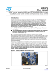
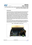
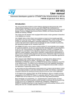
UM1452
User manual
STM32100B-MCKIT motor control starter kit
Introduction
The STM32100B-MCKIT starter kit is an integrated system designed to provide a complete,
ready-to-use motor control application developed around the STMicroelectronics
STM32F100 microcontroller. This starter kit is particularly suited to drive three-phase
brushless permanent magnet synchronous motors and demonstrates how effectively the
low-cost STM32F100 microcontrollers can be used in cost-optimized real-world motor
control applications. For evaluation of higher performance systems, STM3210B-MCKIT
(based on STM32F103 microcontroller) may be used.
The STM32100B-MCKIT supports Field Oriented Control (FOC) drive of three-phase
permanent magnet synchronous motors (PMSM). Single-shunt resistor current
measurement is supported out-of-the-box allowing closed loop torque control. Position
measurement can be implemented using quadrature encoder sensors, Hall effect sensors
or sensorless algorithms.
You can run the STM32100B-MCKIT starter kit in two ways:
■
As a plug-and play, out-of-the-box, demo with the provided PMSM motor, in sensorless
torque or speed control mode.
■
In conjunction with a third-party IDE and C compiler, as a development kit for creating your
own motor control application based on STM32F100.
The CD ROM in the STM32100B-MCKIT contains all relevant manuals and related
documentation including:
■
STM32F100 microcontroller datasheets.
■
STM32 evaluation boards features, peripherals, and connectors are described in the
STM32100B-EVAL user manual (UM0841).
■
STM32 PMSM FOC MC library (also referenced as STM32 PMSM FOC SDK), its
customization and the default program flashed onto the STM32F100B-EVAL, are
described in the Quick start guide for STM32F103xx/STM32F100xx PMSM single/dual
FOC SDK V3.0 (UM1080).
■
STM32 PMSM FOC MC library usage is described in the STM32 FOC PMSM firmware
library user and developer manuals (UM1052 and UM1053, respectively).
In this manual, you will find information on:
■
The STM32100B-MCKIT starter kit components.
■
How to set up the hardware to run the provided PMSM motor.
September 2011
Doc ID 022076 Rev 2
1/12
www.st.com
Contents
STM32100B-MCKIT
Contents
1
STM32100B-MCKIT hardware setup . . . . . . . . . . . . . . . . . . . . . . . . . . . . 3
1.1
Package checklist . . . . . . . . . . . . . . . . . . . . . . . . . . . . . . . . . . . . . . . . . . . . 3
1.1.1
Hardware . . . . . . . . . . . . . . . . . . . . . . . . . . . . . . . . . . . . . . . . . . . . . . . . . 3
1.1.2
Software . . . . . . . . . . . . . . . . . . . . . . . . . . . . . . . . . . . . . . . . . . . . . . . . . . 4
1.1.3
Documentation . . . . . . . . . . . . . . . . . . . . . . . . . . . . . . . . . . . . . . . . . . . . . 5
1.1.4
Components not provided . . . . . . . . . . . . . . . . . . . . . . . . . . . . . . . . . . . . 5
1.1.5
Permanent magnet synchronous motor (PMSM) . . . . . . . . . . . . . . . . . . . 5
1.2
Hardware configuration for PMSM motor . . . . . . . . . . . . . . . . . . . . . . . . . . 6
1.3
Power supply connections . . . . . . . . . . . . . . . . . . . . . . . . . . . . . . . . . . . . . 7
2
Running and customizing the starter kit . . . . . . . . . . . . . . . . . . . . . . . . 8
3
Safety warnings . . . . . . . . . . . . . . . . . . . . . . . . . . . . . . . . . . . . . . . . . . . . . 9
3.1
General . . . . . . . . . . . . . . . . . . . . . . . . . . . . . . . . . . . . . . . . . . . . . . . . . . . . 9
3.2
Intended use . . . . . . . . . . . . . . . . . . . . . . . . . . . . . . . . . . . . . . . . . . . . . . . 9
3.3
Operation . . . . . . . . . . . . . . . . . . . . . . . . . . . . . . . . . . . . . . . . . . . . . . . . . . 9
3.4
Important notice to users . . . . . . . . . . . . . . . . . . . . . . . . . . . . . . . . . . . . . . 9
Appendix A Additional information. . . . . . . . . . . . . . . . . . . . . . . . . . . . . . . . . . . . 10
4
2/12
A.1
Recommended reading . . . . . . . . . . . . . . . . . . . . . . . . . . . . . . . . . . . . . . . 10
A.2
Software upgrades . . . . . . . . . . . . . . . . . . . . . . . . . . . . . . . . . . . . . . . . . . 10
A.3
Getting technical support . . . . . . . . . . . . . . . . . . . . . . . . . . . . . . . . . . . . . 10
Revision history . . . . . . . . . . . . . . . . . . . . . . . . . . . . . . . . . . . . . . . . . . . 11
Doc ID 022076 Rev 2
STM32100B-MCKIT
1
STM32100B-MCKIT hardware setup
STM32100B-MCKIT hardware setup
This section provides a detailed description of the components that are included in the
STM32100B-MCKIT starter kit. It also describes the default settings for a permanent
magnet synchronous motor (PMSM).
1.1
Package checklist
Figure 1 shows the layout and connections of the major components of the STM32100BMCKIT starter kit.
Figure 1.
STM32100B-MCKIT layout
*,).+
53"*4!'
DEBUGGER
%NCODER
CONNECTIONSX
3HINANO
MOTOR
-"
-OTORPHASE
CONNECTIONSX
34%6!,)(-V
*
-"
34-"%6!,
-"
!#$#
POWERADAPTOR
422!
-36
1.1.1
Hardware
The STM32100B-MCKIT starter kit includes the following items:
●
STEVAL-IHM023v2 (MB991) power stage evaluation board (1)
This board is described in the STEVAL-IHM023v2 user manual (UM0723) provided on
the STM32100B-MCKIT CD-ROM.
●
MB871 STM32100B-EVAL evaluation board (2)
This board is described in the STM32100B-EVAL user manual (UM0841) provided on
the STM32100B-MCKIT CD-ROM.
Doc ID 022076 Rev 2
3/12
STM32100B-MCKIT hardware setup
●
MB535B opto-isolation JTAG board (3)
This board is described in the JTAG opto-isolation board user manual (UM0378)
provided on the STM32100B-MCKIT CD-ROM.
The purpose of the JTAG opto-isolation board is to provide galvanic isolation between
the J-link debugger/programmer and the STM32 evaluation board. It helps to prevent
accidental damage to the PC in the event of a catastrophic failure on the motor control
board. This isolation barrier also solves the problem of the PC, JTAG debugger and
motor control board being at different ground potentials.
●
J-link USB–JTAG debugger (4)
The SEGGER J-link USB-JTAG debugger enables you to reprogram the Flash memory
of the STM32 microcontroller and to debug the software before using the application in
standalone mode.
●
24V DC Shinano PMSM motor (5)
The motor included in the STM32100B-MCKIT starter kit is a Shinano inner rotor type
four-pole brushless DC motor with Hall sensor and encoder. For electrical
specifications and mechanical dimensions, refer to the Shinano datasheets on the
STM32100B-MCKIT CD-ROM.
●
AC/DC power adaptor (TR15RA050) (6)
To supply the MB871 board
●
The following cables:
●
1.1.2
STM32100B-MCKIT
–
Motor cables (7)
–
A motor connector HE10 34-pin cable (8)
–
A USB cable (9)
–
Two JTAG cables (10)
STM32100B-MCKIT CD-ROM
Software
The STM32100B-MCKIT CD-ROM includes the following software: STM32 PMSM FOC
SDK v3.0, ST MC Workbench, a PC software for configuring the above-mentioned STM32
FOC PMSM MC library (v3.0 and later).
When you receive the STM32100B-MCKIT, the STM32 microcontroller is programmed by
default with the PMSM sensorless FOC firmware. It is recommended to search for the latest
available version of the firmware (contact your nearest ST office or technical support team,
or look on www.st.com) before starting any new development.
4/12
Doc ID 022076 Rev 2
STM32100B-MCKIT
1.1.3
STM32100B-MCKIT hardware setup
Documentation
The STM32100B-MCKIT CD-ROM includes the following product documentation in PDF
format:
1.1.4
●
STM32F100xx high-, medium- and low-density datasheets
●
STM32F10xxx reference manual
●
STM32100B-MCKIT motor control kit user manual (UM1452, i.e. this manual)
●
STM32 FOC PMSM MC library user manual (UM1052)
●
STM32 FOC PMSM MC library developer manual (UM1053)
●
Quick start guide for PMSM FOC SDK v3.0 (UM1080)
●
STM32100B-EVAL user manual (UM0841)
●
STEVAL-IHM023v2 power stage evaluation board user manual (UM0723)
●
JTAG opto-isolation board user manual (UM0378)
Components not provided
The STM32100B-MCKIT starter kit does not include the 24 V - 3 A (minimum) power supply
required to run the provided PMSM motor.
1.1.5
Permanent magnet synchronous motor (PMSM)
The PM synchronous motor is a rotating electric machine where the stator is a classic threephase stator like that of an induction motor and the rotor has surface-mounted permanent
magnets. In this respect, the PM synchronous motor is equivalent to an induction motor
where the air gap magnetic field is produced by a permanent magnet. The use of a
permanent magnet to generate a substantial air gap magnetic flux makes it possible to
design highly efficient PM motors.
A PM synchronous motor is driven by sine wave voltage coupled with the given rotor
position. The generated stator flux together with the rotor flux, which is generated by a rotor
magnet, defines the torque, and thus speed, of the motor. The sine wave voltage output has
to be applied to the three-phase winding system in such a way that the angle between the
stator flux and the rotor flux is kept close to 90° to get the maximum generated torque. To
meet this criterion, the motor requires electronic control for proper operation.
For a common three-phase PM synchronous motor, a standard three-phase power stage is
used. The power stage uses six power transistors with independent switching. The power
transistors are switched in the complementary mode. The sine wave output is generated
using the space vector PWM technique.
Doc ID 022076 Rev 2
5/12
STM32100B-MCKIT hardware setup
1.2
STM32100B-MCKIT
Hardware configuration for PMSM motor
This section describes the procedure for operating the STM32100B-MCKIT with a PMSM
motor.
When you are running the PMSM motor, follow these steps:
1.
Verify that all the jumpers on the motor control board (MB991) are in their default
position.
Refer to Table 1 for information on jumper settings, and if necessary, to the STEVALIHM023v2 user manual (UM0723) for the location of the jumpers on the board.
2.
Verify that all of the STM32100B-EVAL evaluation board (MB871) jumpers are in their
default position.
Refer to Table 2 for information on jumper settings, and if necessary, to the
STM32100B-EVAL evaluation board user manual (UM0841) for the location of jumpers
on the board.
3.
Verify that the PMSM motor cables are correctly plugged into the STEVAL-IHM023v2
connectors J2 and J4.
The STEVAL-IHM023v2, the STM32100B-EVAL evaluation board (MB871), the optoisolation JTAG board (MB535B), and the provided PMSM motor are already assembled
together over a metal support when you receive the kit.
4.
Verify that the STM32100B-EVAL evaluation board and the JTAG opto-isolation board
(MB535B) are connected with the provided 20-pin JTAG cable.
In this way, the STM32100B-EVAL evaluation board automatically supplies the optoisolation board.
5.
Power up the STM32100B-EVAL evaluation board with the auxiliary AC/DC power
adaptor (TR15RA050).
6.
Power up the power stage board (STEVAL-IHM023v2) by connecting the output
terminals of your DC power supply to the “MAINS” connector (J1).
The provided voltage must be 24 V DC and your power supply must be able to provide
a current of 3 A.
The STM32100B-MCKIT is now ready to run with the PMSM motor.
Caution:
6/12
Before supplying power to the board, double check proper connections, make sure that
there are no metal parts on, below or around the PCB and that there are no undesired
earth/ground loops due to measuring equipment such as an oscilloscope.
Doc ID 022076 Rev 2
STM32100B-MCKIT
Table 1.
STM32100B-MCKIT hardware setup
STEVAL-IHM023v2 board jumper settings for a PMSM motor (default)
Jumper
Settings for the provided
Settings for a high-voltage
Shinano 24 V PMSM motor
PMSM motor
W1
3.3 V position
W3
“< 35 V only”
“< 35 V only” or “HIGH VOLTAGE”
W4
Present
W5
“R_BRAKE” position
W6
Not present
W7
Not present
W8
Present
W9
Present, in “1 shunt” position (opposite to silkscreen)
W10
Present and soldered on default position of silkscreen printing
W11
Present in silkscreen position
W13
Present, in “1 shunt” position (opposite to silkscreen printing)
W14
Not present
W16
Present (opposite to silkscreen printing)
Table 2.
STM32100B-EVAL board jumper settings for a PMSM motor (default)
Jumper
JP10
Set to PSU position to supply the STM32100B-EVAL evaluation board through
the jack (CN8)
JP6
Not fitted (Hall effect sensors/tachogenerator signal filtering)
SW1, SW2
1.3
Description
Both set to “0” position to boot from embedded user Flash
Power supply connections
Refer to Section 3.3.1 of the STEVAL-IHM023v2 user manual (UM0723) to know more
about the possible connections for the STEVAL-IHM023v2 power supply stage.
Doc ID 022076 Rev 2
7/12
Running and customizing the starter kit
2
STM32100B-MCKIT
Running and customizing the starter kit
When you receive the STM32100B-MCKIT starter kit, the STM32 microcontroller is already
programmed with the PMSM sensorless FOC firmware, enabling you to immediately run the
PMSM motor included in the kit.
It is also possible to change some starter kit components, for instance the provided PMSM
24V Shinano motor can be replaced with any PMSM/BLDC three-phase motor, and can also
use a different control stage and/or power stage.
As the ST standard motor control connector is fitted on most of the available ST evaluation
boards, it is possible to use different power stages (with different rated power, supply
voltage, nominal current,...) in conjunction with different STM32 evaluation boards
(STM32100E-EVAL, STEVAL-IHM022v1,...) on condition that the STM32 FOC PMSM SDK
v3.0 is properly configured through the ST MC Workbench PC software.
For more details refer to:
8/12
●
www.st.com to find out about the available products and/or systems evaluation boards
●
Products and/or systems evaluation boards documentation for information related to
the hardware configuration of these boards
●
The 'Quickstart guide for STM32 PMSM MC Library v3.0' (UM1080, §3.2) to know
more about firmware customization and programming
Doc ID 022076 Rev 2
STM32100B-MCKIT
3
Safety warnings
3.1
General
Safety warnings
In operation, the STM32100B-MCKIT starter kit has noninsulated wires, moving or rotating
parts (when connected to a motor), as well as hot surfaces. In case of improper use,
incorrect installation or misuse, there is danger of serious personal injury and damage to
property. All operations, installation and maintenance are to be carried out by skilled
technical personnel (applicable accident prevention rules must be observed).
When the motor control board is supplied with voltages greater than 30 V AC/DC, all of the
board and components must be considered “hot”, and any contact with the board must be
avoided. The operator should stay away from the board as well (risk of projection of material
in case of component destruction, especially when powering the board with high voltages).
The rotating parts of motors are also a source of danger.
The STM32100B-MCKIT starter kit contains electrostatic sensitive components which may
be damaged through improper use.
3.2
Intended use
The STM32100B-MCKIT starter kit is made of components designed for demonstration
purposes and must not be included in electrical installations or machinery. Instructions
about the setup and use of the STM32100B-MCKIT starter kit must be strictly observed.
3.3
Operation
After disconnecting the board from the voltage supply, several parts and power terminals
must not be touched immediately because of possible energized capacitors or hot surfaces.
3.4
Important notice to users
While every effort has been made to ensure the accuracy of all information in this document,
STMicroelectronics assumes no liability to any party for any loss or damage caused by
errors or omissions or by statements of any kind in this document, its updates, supplements,
or special editions, whether such errors are omissions or statements resulting from
negligence, accident, or any other cause.
Doc ID 022076 Rev 2
9/12
Additional information
Appendix A
A.1
STM32100B-MCKIT
Additional information
Recommended reading
This documentation describes how to use the STM32100B-MCKIT Starter Kit. Additional
information can be found in the following documents:
●
STM32F100xx low- and medium- density datasheets
●
STM32F10xxx reference manual (RM0008)
●
STMicroelectronics motor control application notes
●
STM32100B-EVAL evaluation board user manual (UM0841)
●
JTAG opto-isolation board user manual (UM0378)
●
STEVAL-IHM023v2 power stage evaluation board user manual (UM0723)
●
STM32 FOC PMSM MC library user manual (UM1052)
●
STM32 FOC PMSM MC library developer manual (UM1053)
●
Quick start guide for PMSM FOC SDK v3.0 (UM1080)
All the above documents can be found on the STM32100B-MCKIT CD-ROM.
A.2
Software upgrades
The latest versions of the STM32 motor control libraries are available, free of charge, from
our sales offices.
A.3
Getting technical support
Technical assistance is provided free to all customers. For technical assistance,
documentation and information about products and services, please refer to your local
STMicroelectronics partner.
10/12
Doc ID 022076 Rev 2
STM32100B-MCKIT
4
Revision history
Revision history
Table 3.
Document revision history
Date
Revision
Changes
09-Sept-2011
1
Inital release
16-Sept-2011
2
Modified description of TR15RA050 in Section 1.1.1
Added customization information in Chapter 2
Doc ID 022076 Rev 2
11/12
STM32100B-MCKIT
Please Read Carefully:
Information in this document is provided solely in connection with ST products. STMicroelectronics NV and its subsidiaries (“ST”) reserve the
right to make changes, corrections, modifications or improvements, to this document, and the products and services described herein at any
time, without notice.
All ST products are sold pursuant to ST’s terms and conditions of sale.
Purchasers are solely responsible for the choice, selection and use of the ST products and services described herein, and ST assumes no
liability whatsoever relating to the choice, selection or use of the ST products and services described herein.
No license, express or implied, by estoppel or otherwise, to any intellectual property rights is granted under this document. If any part of this
document refers to any third party products or services it shall not be deemed a license grant by ST for the use of such third party products
or services, or any intellectual property contained therein or considered as a warranty covering the use in any manner whatsoever of such
third party products or services or any intellectual property contained therein.
UNLESS OTHERWISE SET FORTH IN ST’S TERMS AND CONDITIONS OF SALE ST DISCLAIMS ANY EXPRESS OR IMPLIED
WARRANTY WITH RESPECT TO THE USE AND/OR SALE OF ST PRODUCTS INCLUDING WITHOUT LIMITATION IMPLIED
WARRANTIES OF MERCHANTABILITY, FITNESS FOR A PARTICULAR PURPOSE (AND THEIR EQUIVALENTS UNDER THE LAWS
OF ANY JURISDICTION), OR INFRINGEMENT OF ANY PATENT, COPYRIGHT OR OTHER INTELLECTUAL PROPERTY RIGHT.
UNLESS EXPRESSLY APPROVED IN WRITING BY TWO AUTHORIZED ST REPRESENTATIVES, ST PRODUCTS ARE NOT
RECOMMENDED, AUTHORIZED OR WARRANTED FOR USE IN MILITARY, AIR CRAFT, SPACE, LIFE SAVING, OR LIFE SUSTAINING
APPLICATIONS, NOR IN PRODUCTS OR SYSTEMS WHERE FAILURE OR MALFUNCTION MAY RESULT IN PERSONAL INJURY,
DEATH, OR SEVERE PROPERTY OR ENVIRONMENTAL DAMAGE. ST PRODUCTS WHICH ARE NOT SPECIFIED AS "AUTOMOTIVE
GRADE" MAY ONLY BE USED IN AUTOMOTIVE APPLICATIONS AT USER’S OWN RISK.
Resale of ST products with provisions different from the statements and/or technical features set forth in this document shall immediately void
any warranty granted by ST for the ST product or service described herein and shall not create or extend in any manner whatsoever, any
liability of ST.
ST and the ST logo are trademarks or registered trademarks of ST in various countries.
Information in this document supersedes and replaces all information previously supplied.
The ST logo is a registered trademark of STMicroelectronics. All other names are the property of their respective owners.
© 2011 STMicroelectronics - All rights reserved
STMicroelectronics group of companies
Australia - Belgium - Brazil - Canada - China - Czech Republic - Finland - France - Germany - Hong Kong - India - Israel - Italy - Japan Malaysia - Malta - Morocco - Singapore - Spain - Sweden - Switzerland - United Kingdom - United States of America
www.st.com
12/12
Doc ID 022076