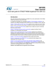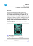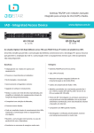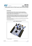
1
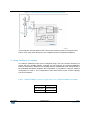
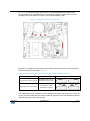
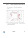
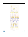
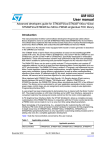
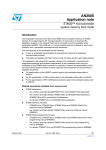
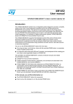
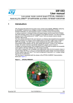
DT0026
Design tip
Field oriented control of PMSM motor exploiting
SLLIMMTM nano and STM32F302x/303x
By Gianluigi Forte, Dino Costanzo
Main components
STM32F302x
STM32F303x
Analog and DSP with FPU ARM Cortex-M4 MCU up to
256KB Flash+48KB SRAM 4 ADCs, 2 DAC ch., 7 comp, 4
PGA, timers, 2.0-3.6 V operation
Introduction
The “3-phase high voltage inverter power board features the STGIPN3H60A (SLLIMM™nano) for field-oriented control (FOC) of permanent magnet synchronous motors (PMSM)”,
also referred to by the order code STEVAL-IHM045V1, is designed to perform the FOC of
sinusoidal-shaped back-EMF PMSMs with or without sensors, with nominal power up to
100 W.
The aim of this technical note is to describe how to setup the STEVAL-IHM045V1 power
board to work together with the STM32303C-EVAL control board and the STM32 PMSM
FOC SDK firmware and to setup a complete Motor control drives able to run a PMSM
motor taking the advantage of the embedded peripheral of the STM32F302x/303x
microcontroller.
1. Take benefit of embedded peripheral of STM32F302x/303x
The STM32F302x/303x microcontrollers embed a set of peripherals dedicated to resolve
common motor control issues by reducing the number of required external components.
Figure 1 shows the overcurrent protection network and the current sensing network that
can be implemented using the internal resources of the STM32F302x/303x.
April 2014
DT0026 Rev 2
1/10
www.st.com
Figure 1 - Overcurrent protection and current sensing network
These networks are replicated for each of the shunt resistors present in the power board
and for each motor drive having up to six comparator and four operational amplifiers
2. Using Configure the system
The STEVAL-IHM045V1 board can be configured using a set of 0 Ω resistor used as 2-pin
jumper with two possible settings: mounted and not mounted. The STEVAL-IHM045V1
board is configured by default to work together with the STM32303C-EVAL taking benefit of
the embedded operational amplifiers and comparators. It is possible to verify the resistors
configuration in Table 1. This configuration is also called “Direct motor currents sampling
from shunt resistors”.
Table 1 - STEVAL-IHM045V1 resistors configuration to use embedded OPAMPs and COMPs
Resistors
Configuration
R55, R56, R57 Mounted (0Ω)
R58, R69, R79 Not mounted
April 2014
DT0026 Rev 2
2/10
www.st.com
In Figure 2 is shown the layout of the board. In red are highlighted the position of the
components that can be modified when is required to swap from “Direct motor currents
sampling from shunt resistors” mode to “Use external OPAMP” mode.
Figure 2 - Changing current sensing network
Moreover it is possible to select either single shunt or three shunts for the current sensing
network topology as described in Table 2.
Table 2 - Jumpers settings for the current sensing network topology selection
Topology
Jumpers setting
Three shunts current reading
J9 between pins 1 and 2
J10 between pins 1 and 2
Single shunt current reading
J9 between 2 and 3
J10 between 2 and 3
Jumpers settings
The STM32303C-EVAL evaluation board supports both single and dual motor control via
34-pin connectors CN2 and CN4, which provide all required control and feedback signals to
and from the motor power-driving board.
April 2014
DT0026 Rev 2
3/10
www.st.com
Some PCB reworks are needed for motor control applications to disconnect peripherals
which share I/Os with motor control connectors and connect these I/Os to motor control
connectors.
To configure the board for motor control application, please follow the procedure below:
1. Remove even number resistors from R1 to R58 (R2, R4, R6….R56,
R58 except R12, R22). The resistor positions on the PCB board are
shown in Figure 3.
Figure 3 - Resistor position on the PCB board: even number removing
2. Mount odd number resistors from R1 to R58 (R1, R3….R55, R57 except R11
which is mounted by default) with a 0-ohm resistor. The resistor positions on the
PCB board are shown in Figure 4.
April 2014
DT0026 Rev 2
4/10
www.st.com
Figure 4 - Resistor positions on the PCB board: odd number mounting
In the Table 3 are reported the configurations of STM32303C-EVAL board switches and
solder bridges to connect the “Direct motor currents sampling from shunt resistors” coming
from the STEVAL-IHM045V1 to the embedded OPAMPs and COMPs.
Table 3 - Motor control related switches and solder bridges in STM32303C-EVAL
3SA
PG3SA
PGM
OAM
PG3SA
PGM1
OAM1
PGM2
OAM2
Other
condition
Description
Motor 1
3SA
Motor 2
3SA
April 2014
PG3SA
R113, R116
MC1_CurrentA+ connect to OPAMP1_IN+(PA1)
mounted SB2 MC1_CurrentB+ connect to OPAMP2_IN1+(PA7)
open
MC1_CurrentC+ connect to OPAMP2_IN2+(PD14)
R132, R134
mounted
SB5 open
DT0026 Rev 2
MC2_CurrentA+ connect to OPAMP3_IN+(PB0)
MC2_CurrentB+ connect to OPAMP4_IN2 +(PB13)
MC2_CurrentC+ connect to OPAMP4_IN1+(PB11)
5/10
www.st.com
In Figure 5 is shown the section of the STM32303C-EVAL board schematic
related to the motor control signal conditioning that can be useful to
understand the configuration of the switched and solder bridge described in
Table 3.
April 2014
DT0026 Rev 2
6/10
www.st.com
Figure 5 - Schematic of motor control section of the STM32303C-EVAL
April 2014
DT0026 Rev 2
7/10
www.st.com
3. How to configure the firmware
For project based on STM32F302/303, the STM32 FOC SDK v3.4 supports the embedded
PGA and the hardware over current protection for the following configurations:
1. Single drive using single shunt and three shunts current feedback
topologies,
2. Dual drive using any combination of single shunt and three shunts
current feedback topologies.
To enable these functionalities is possible to check the “Embedded PGA” and/or the
“Embedded HW OCP” radio buttons in the ST MC workbench like shown in figure below.
Figure 6 - Schematic of daughter board
4.
Support material
Related design support material
STM32303C-EVAL – product evaluation board for STM32F303xx microcontrollers
STEVAL-IHM045V1 - 3-phase high voltage inverter power board for FOC based on
STGIPN3H60A (SLLIMM™-nano)
Documentation
Datasheet STM32F303x
Datasheet STM32F302x
User manual UM1567 - STM32303C-EVAL evaluation board
User manual UM1052 - STM32F05xx/STM32F100xx/STM32F103xx/STM32F2xx/
STM2F30x/STM32F4xx PMSM single/dual FOC SDK v3.4
User manual UM1703 - 3-phase high voltage inverter power board for FOC based on
STGIPN3H60A (SLLIMM™-nano)
April 2014
DT0026 Rev 2
8/10
www.st.com
5.
Revision history
Date
April 2014
Version
Changes
28-Apr-2014
1
Initial release
29-Apr-2014
2
Updated title in cover page.
DT0026 Rev 2
9/10
www.st.com
Please Read Carefully
Information in this document is provided solely in connection with ST products. STMicroelectronics NV and its subsidiaries
(“ST”) reserve the right to make changes, corrections, modifications or improvements, to this document, and the products and
services described herein at anytime, without notice.
All ST products are sold pursuant to ST’s terms and conditions of sale.
Purchasers are solely responsible for the choice, selection and use of the ST products and services described herein, and ST
assumes no liability whatsoever relating to the choice, selection or use of the ST products and services described herein.
No license, express or implied, by estoppel or otherwise, to any intellectual property rights is granted under this document. If
any part of this document refers to any third party products or services it shall not be deemed a license grant by ST for the
use of such third party products or services, or any intellectual property contained therein or considered as a warranty
covering the use in any manner whatsoever of such third party products or services or any intellectual property contained
therein.
UNLESS OTHERWISE SET FORTH IN ST’S TERMS AND CONDITIONS OF SALE ST DISCLAIMS ANY EXPRESS OR
IMPLIED WARRANTY WITH RESPECT TO THE USE AND/OR SALE OF ST PRODUCTS INCLUDING WITHOUT
LIMITATION IMPLIED WARRANTIES OF MERCHANTABILITY, FITNESS FOR A PARTICULAR PURPOSE (AND THEIR
EQUIVALENTS UNDER THE LAWS OF ANY JURISDICTION), OR INFRINGEMENT OF ANY PATENT, COPYRIGHT OR
OTHER INTELLECTUAL PROPERTY RIGHT.
ST PRODUCTS ARE NOT DESIGNED OR AUTHORIZED FOR USE IN: (A) SAFETY CRITICAL APPLICATIONS SUCH
AS LIFE SUPPORTING, ACTIVE IMPLANTED DEVICES OR SYSTEMS WITH PRODUCT FUNCTIONAL SAFETY
REQUIREMENTS; (B) AERONAUTIC APPLICATIONS; (C) AUTOMOTIVE APPLICATIONS OR ENVIRONMENTS,
AND/OR (D) AEROSPACE APPLICATIONS OR ENVIRONMENTS. WHERE ST PRODUCTS ARE NOT DESIGNED FOR
SUCH USE, THE PURCHASER SHALL USE PRODUCTS AT PURCHASER’S SOLE RISK, EVEN IF ST HAS BEEN
INFORMED IN WRITING OF SUCH USAGE, UNLESS A PRODUCT IS EXPRESSLY DESIGNATED BY ST AS BEING
INTENDED FOR “AUTOMOTIVE, AUTOMOTIVE SAFETY OR MEDICAL” INDUSTRY DOMAINS ACCORDING TO ST
PRODUCT DESIGN SPECIFICATIONS. PRODUCTS FORMALLY ESCC, QML OR JAN QUALIFIED ARE DEEMED
SUITABLE FOR USE IN AEROSPACE BY THE CORRESPONDING GOVERNMENTAL AGENCY.
Resale of ST products with provisions different from the statements and/or technical features set forth in this document shall
immediately void any warranty granted by ST for the ST product or service described herein and shall not create or extend in
any manner whatsoever, any liability of ST.
ST and the ST logo are trademarks or registered trademarks of ST in various countries.
Information in this document supersedes and replaces all information previously supplied.
The ST logo is a registered trademark of STMicroelectronics. All other names are the property of their respective owners.
© 2014 STMicroelectronics - All rights reserved
STMicroelectronics group of companies
Australia - Belgium - Brazil - Canada - China - Czech Republic - Finland - France - Germany - Hong Kong - India - Israel Italy - Japan - Malaysia - Malta - Morocco - Philippines - Singapore - Spain - Sweden - Switzerland - United Kingdom - United
States of America
www.st.com
April 2014
DT0026 Rev 2
10/10
www.st.com