1
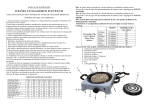
StillClean 100 User’s Guide OSI Environmental Inc. Anoka, MN Last Revised: 7/19/13 This Page intentionally left blank. TABLE OF CONTENTS IMPORTANT SAFETY INSTRUCTIONS ........................................................................................ 2 INTRODUCTION ............................................................................................................................. 4 DESCRIPTION OF KEY COMPONENTS ....................................................................................... 5 EQUIPMENT SETUP ...................................................................................................................... 7 TROUBLESHOOTING .................................................................................................................. 10 MAINTENANCE ............................................................................................................................ 11 SPECIFICATIONS......................................................................................................................... 11 ELECTRICAL SCHEMATIC ......................................................................................................... 13 WARRANTY INFORMATION ....................................................................................................... 14 APPENDIX A ................................................................................................................................. 15 APPENDIX B ................................................................................................................................. 16 APPENDIX C ................................................................................................................................. 17 -1- IMPORTANT SAFETY AND USE INSTRUCTIONS READ BEFORE OPERATING Read and understand the operators manual completely prior to starting the system. Failure to do so may damage the unit and void the warranty. The intake filter MUST be utilized at all times to avoid plugging the machine with solids. DO NOT drop the intake filter to the bottom of the parts washer tank or it will plug prematurely. Depending upon the type of filter it should be suspended about midway into the solvent reservoir. This system is designed to work ONLY with the parts washing solvents specified in the manual. Eventually, dirty solvent becomes unrecyclable, to begin use of this system you MAY find that you need to start with fresh product. DO NOT allow water to be introduced into the system, this will cause it to malfunction. Keep this manual in a place that is always readily accessible to the user. CAUTION – Burn Hazard due to hot oil. Allow unit to cool to 150º F before draining oil from distillation chamber. CAUTION – Risk of electric shock, do not remove cover (or back). No userserviceable parts inside. Refer servicing to qualified service personnel. WARNING – For continued protection against risk of electric shock, fire, and explosion, comply with the following requirements: Connect this equipment to a properly grounded outlet only. Do not operate this equipment with a damaged cord or if the equipment has been dropped or damaged; wait until it has been examined and repaired by a qualified service person. If an extension cord is necessary, be sure to arrange the cord so that it will not be tripped over or pulled. Always unplug this equipment from the electrical outlet when not in use. Never yank the cord to pull the plug from the outlet. Grasp the plug and pull to disconnect. -2- WARNING – To reduce the risk of fire or explosion, install, operate and maintain this equipment in accordance with the instruction manual and the following precautions: This equipment has internal arcing or sparking parts that must not be exposed to flammable vapors. This equipment must be located at least 18 inches (460 mm) above floor level. This equipment must only be used with a parts cleaner having a functional, unobstructed safety lid. Do not operate this equipment in the vicinity of open containers of flammable liquid (e.g. gasoline) or in the presence of aerosols. Never use solvents containing unstable reactives, such as nitrocellulose. The solvent being cleaned by this equipment must only consist of nonchlorinated mineral spirits with an autoignition temperature greater than 415º F (213º C). The flash point of the solvent being used must be higher than the maximum room temperature where the equipment is operated. Select the solvent as follows: ROOM TEMPERATURE RANGE Up to 100º F (38º C) 100º F (38º C) to 120º F (49º C) BOILING POINT RANGE (SEA LEVEL) 315º F (157º C) to 400º F (205º C) 350º F (177º C) to 400º F (205º C) MINIMUM CLOSED-CUP FLASH POINT 105º F (41º C) 140º F (60º C) CAUTION – To reduce the risk of fire or explosion, install, operate, and maintain this equipment in accordance with the instruction manual. This unit is for use in an ambient temperature environment, as delineated in the above table, with no forced ventilation. Under these conditions, the unit shall be spaced a minimum of 6 inches (14 cm) from potential sources of ignition such as electrical receptacles, switches, pilot lights, fixtures, contacts, and other similar equipment that can produce sparks. This unit has only been investigated for use with the solvents listed in the above table. SAVE THESE INSTRUCTIONS -3- INTRODUCTION NOTICE ATTEMPTING TO OPERATE THIS EQUIPMENT WITHOUT READING THIS MANUAL WILL LIKELY CAUSE THE EQUIPMENT TO FAIL AND MAY VOID YOUR WARRANTY. Your StillClean solvent recycler is designed to recycle specified petroleum-based solvents used in degreasing operations. The unit operates by drawing the oily solvent into a distillation chamber and heating it under vacuum to its boiling point. As the solvent has a much lower boiling point than the oil, the solvent will boil off first, with the solvent vapor being drawn out through the condenser. In the condenser the solvent is cooled, returning it to a liquid for reuse in the parts cleaner. Once every two minutes the clean solvent that has collected in the solvent accumulator will be returned to the cleaning basin and a little more oily solvent will be brought into the distillation chamber. When the fluid in the distillation chamber no longer contains any solvent to distill, a thermostat is thrown and the “Oil Full” indicator turns on. After the distillation chamber has cooled below 150 degree Fahrenheit, the user drains the oil from the unit, resets the thermostat and turns the unit back on and the cycle is repeated. After initially setting up the StillClean unit with the adjacent parts cleaner, the unit will run continuously and automatically. The StillClean unit requires minimal user servicing, including draining the used oil and servicing the air and solvent filters. The StillClean unit is designed to draw dirty solvent from the same tank that it discharges the clean solvent back into (see Appendix A.) This allows the user to continue using the parts cleaner even while the StillClean unit is recycling the solvent. Typical users will find that the solvent only needs to be recycled once every week or two. The StillClean unit is designed so that it can be easily stored under a bench when not in use. -4- DESCRIPTION OF KEY COMPONENTS The front panel of the StillClean unit contains the following controls and indicators: 1. POWER SWITCH: To turn the unit ON, toggle the switch upward. 2. AIR PRESSURE GAUGE: This gauge allows easy monitoring of the regulated air pressure that is used for generating the vacuum within the StillClean unit. When the unit is operating, the gauge pressure should read approximately 90 psi. The air pressure can be adjusted as required to maximize the internal vacuum of the system. 3. VACUUM GAUGE: The vacuum gauge allows easy verification that the vacuum generator is operating properly, the valves are closed (the oil drain valve and the oil drain vent) and the vacuum seals are tight. When the unit is operating, the vacuum gauge should read approximately 27 inches of mercury at sea level. 4. OIL DRAIN VENT: Removing this cap allows air to enter the distillation chamber while the used oil is being drained. Failure to remove this cap prior to draining the used oil will cause the oil to either come out extremely slowly or not at all. Following the oil-draining step, replace the cap to provide a vacuum-tight seal. A tether captures the cap so it is not misplaced during the venting step. 5. “FULL ACCUMULATOR” LIGHT: Whenever this light is illuminated, the solvent accumulator is full due to insufficient draining during the drain-down portion of the distillation cycle. Disconnection of the solvent-discharge hose retainer clip from the basin of the parts cleaner usually causes this condition. 6. “FULL OIL” LIGHT: This light, adjacent to the oil-drain valve, illuminates when the temperature of the distillation chamber reaches approximately 310º F. For a properly operating unit, this indicates that the distillation chamber is full of used oil. This light is also the reset switch button. After draining the oil, push the illuminated button to start the distillation process again. 7. TEMPERATURE GAUGE: This thermometer is adjacent to the oil drain valve. It monitors the temperature of the distillation chamber and its contents. TO PREVENT BURNS DUE TO HOT OIL, ALWAYS ALLOW THE UNIT TO COOL BELOW THE RED ZONE ON THE THERMOMETER BEFORE DRAINING THE OIL. 8. OIL DRAIN VALVE: This is a quarter-turn type with a red plastic actuator. To drain the used oil, once it has cooled, position the used oil container under the valve, open the oil drain vent on front-panel, and open the oil drain valve with a quarter-turn motion. The valve is closed when it is positioned horizontally, and open when positioned vertically. Close the oil drain valve and oil drain vent after the oil has been drained. The oil drain valve outlet has a section of tubing installed -5- for mounting a 3/8-inch ID drain hose if so desired. A length of 3/8inch petroleum-resistant hose, such as fuel hose, will work well. 9. COOLING FAN WITH AIR FILTER: This fan provides cooling air to the solvent condenser. An air filter at the fan inlet traps dirt that would otherwise collect in the condenser fins. A clogged filter reduces the amount of air passing through the condenser, reducing the rate of solvent recovery. See the MAINTENANCE section for filter cleaning instructions. The rear panel of the StillClean unit contains the following components: 1. SOLVENT ACCUMULATOR: This container collects the distilled solvent. At approximately 2-minute intervals, the solvent drain valve opens for approximately 20 seconds, allowing the clean solvent to drain back into the basin of the parts cleaner. 2. SUCTION HOSE: The oily solvent is drawn into the StillClean unit through this hose. To maintain vacuum within the StillClean unit, the solvent level in the reservoir of the parts cleaner must be high enough to fully cover the inlet filter mounted on the end of the suction hose. 3. INLET FILTER: This automotive spin-on oil filter must always be installed on the suction hose to keep sediment in the solvent reservoir from clogging the internal orifices of the StillClean unit. A clogged filter will cause the “Oil Full” light to illuminate prematurely because the flow of incoming solvent/oil mixture is not sufficient to keep up with the solvent boil-off rate. See the MAINTENANCE section for inlet filter servicing instructions. 4. SOLVENT-DISCHARGE HOSE: Clean, clear solvent is returned to your parts cleaner through this hose. The hose is attached to a retractor, which will pull the hose up above the accumulator if the hose becomes detached from the cleaning basin. Since the solvent returns to the cleaning basin via gravity from the solvent accumulator, solvent will not flow out of the accumulator when the solvent-discharge hose is fully retracted, causing the “Full Accumulator” light to be illuminated, which will stop the distillation process. 5. AIR SUPPLY PORT: This port accommodates a quick-disconnect fitting having a ¼-inch national pipe thread (NPT) connection. The air supply must be filtered, and oil-free. The air supply pressure must be 90 to 125 psi. Note: The internal air pressure of the unit should be adjusted to approximately 80 psi. 6. AIR PRESSURE ADJUSTMENT SLOT: A slot just to the left of the air supply port allows for adjustment of the internal air pressure of the StillClean unit. The air pressure is adjusted with a regular screwdriver through this slot. The internal air pressure of the unit (according to the air pressure gauge) should be about 80 psi for optimal system performance. -6- EQUIPMENT SETUP Items you will need for proper setup of the StillClean unit: 1. 120 Volt Units: 120-volt, 50/60-Hz, 15-ampere power outlet with protective grounding connection 2. Dry, oil-free Shop air supply at 90 to 175 psi (internal air pressure should be adjusted to 77 - 83 psi) 3. Parts cleaner designed for and using approved petroleum-based solvent (see Appendix B) 4. Empty metal pail for collecting the used oil The StillClean can be adapted to fit most petroleum-based parts cleaners on the market today. See Appendix A for proper connection to your type of equipment. The StillClean unit is designed to automatically draw solvent from the parts cleaner, recycle that solvent, and then return it to the parts cleaner. Proper setup is required. IMPORTANT: The StillClean unit is designed to operate with only the specified solvent and oil. There must be no water, chlorine, or large amounts of solids and sediments in the solvent being recycled. Water in the solvent significantly reduces the ability to separate the solvent from the oil. Chlorine will cause significant corrosion and early failure. Large amounts of solids cause premature clogging of the inlet filter on the suction tube. 1. Install the SUCTION HOSE to the parts cleaner. The 1/8-inch suction hose, complete with its spin-on inlet filter, should be placed inside the solvent reservoir of the parts cleaner. The filter assembly simply rests on the bottom of the reservoir, fully submerged below the liquid level. Attaching the suction hose to the pump post with nylon tie-wraps works well for parts cleaners that have a rigidly suspended pump. To maintain vacuum within the StillClean unit, the inlet filter must always be fully submerged in the solvent reservoir. Because of solvent drag-out over time, be sure to start with a solvent level that is at least 1 foot (30 cm) above the top of the inlet filter. IMPORTANT: Make sure that the end of the suction hose that connects to the StillClean does not have the potential of hanging below the solvent level in your drum or tank. Failure to do so will cause solvent to be siphoned all over your floor after disconnecting the suction hose from the StillClean because the hose will still be full of solvent. 2. Attach the SOLVENT-DISCHARGE HOSE. Be sure to attach the solventdischarge hose properly, as the unit will not work if the solvent-discharge hose is installed incorrectly. The StillClean unit must be located high enough to assure that the solvent in the accumulator properly drains into the basin of the parts cleaner. Be sure that the bottom of the rear-panel cavity surrounding the solvent accumulator is above the top of the U-tube in the -7- solvent-discharge hose. If the accumulator is below the top of the U-tube, the accumulator will not be able to return the clean solvent to your parts cleaner, which will turn on the “Full Accumulator” light and halt the distillation process. Connect the jaws of the solvent-discharge hose retractor clip to the paint-free lip of the cleaning basin. The retractor clip is flexibly mounted to the solventdischarge hose to accommodate basin edges that are either rolled downward or outward. The retractor mechanism maintains constant pressure on the retractor clip, providing an electrical bond between the parts cleaner and the StillClean unit. If the retractor clip becomes disconnected, the retractor mechanism lifts the solvent-discharge hose above the base of the solvent reservoir, preventing discharge of the solvent. To assure that the safety lid of the parts cleaner closes properly in case of fire, make sure that the solvent-discharge hose retractor clip clamps to the lip of the cleaning basin in a manner that does not obstruct closure of the safety lid. FOR FIRE PROTECTION, THE SAFETY LID OF THE PARTS CLEANER MUST CLOSE FULLY WITHOUT ANY OBSTRUCTION. The U-tube in the solvent-discharge hose is designed to compress when the safety lid closes on it, thereby allowing the safety lid to fulfill its function. 3. Attach the air hose. A ¼-inch (¼-18 NPT) threaded port is provided to accept a male quick-disconnect air hose fitting. Thread the quick-disconnect fitting onto the port using Teflon thread sealant. IMPROPERLY APPLIED JOINT-SEALING TAPE CAN CLOG THE AIR ORIFICE. If using Teflon tape, be sure that the tape wrapped around the male threads of the quickdisconnect fitting is always at least 1/16 inch from the end of the fitting. Connect an oil-free, dry air supply of 90 to 175 psi. 4. Attach the oil drain hose, if desired. A short length of 3/8-inch tubing has been provided on the oil drain valve to allow a piece of 3/8-inch ID flexible hose to be added for routing the used oil to the used oil container, if so desired. Be sure that any hose used is suitable for a temperature of 300º F (150º C). 5. Connect the power cord. If the supply cord is damaged, it must be replaced by the manufacturer or its agent. The power cord plugs into the appropriate 120V, 15-ampere, 50/60 Hz outlet. For electric-shock protection, do not defeat the protective grounding connection. If your outlet does not have the required three terminals, enlist the services of a licensed electrician to provide the proper outlet. Do not remove the protective grounding pin of the power plug or use a 3-to-2-pin adapter. 6. Verify that the OIL DRAIN VENT is snuggly tightened and closed. The vent cap must be securely installed to allow sufficient vacuum in the distillation chamber. If the cap is not properly installed, the vacuum system -8- will leak and the StillClean distillation process will not start. Simply turn the cap clockwise to seat it. 7. Power the unit ON. Once the StillClean unit is properly set up per the above procedure, simply move the power switch on the front panel to the ON position and the unit will start cleaning your solvent. 8. Verify proper operation. The gauges on the front panel should indicate the specified minimum air pressure and vacuum readings as specified in the SPECIFICATIONS section. If the “Full Oil” light is on, simply push the illuminated button to reset the thermostat. The heater should then start heating the solvent/oil mixture in the distillation chamber. After the unit’s temperature has stabilized following warm-up of about 20 minutes, clean solvent should be coming from the solvent discharge hose into the basin of the parts cleaner. 9. Optimize system vacuum. The unit’s internal air pressure regulator can be adjusted to maximize the vacuum in the system. Once the system is properly operating as described above, the vacuum can be fine-tuned for optimum performance. With the unit operating, adjust the air pressure using a regular screwdriver. The air pressure adjustment slot is in the back panel. While the unit is operating, slowly lower the air pressure (as measured by the air pressure gauge on the front of your machine) by rotating the air pressure adjustment control downward with the screwdriver until the vacuum drops. Then slowly increase the air pressure back up (by rotating the air pressure adjustment control upwards) just until the vacuum stops increasing. This is the optimum setting for the vacuum generator (normally about a 80 psi reading on the front-panel pressure gauge.) Do not increase the air pressure beyond this point. -9- TROUBLESHOOTING If the StillClean unit does not operate properly, perform the following checks: 1. Be sure that the proper solvent is being used. See APPENDIX B to determine the correct solvent to use. 2. Assure that liquid in the solvent reservoir completely covers the inlet filter mounted on the suction hose. Because of the variation of solvent volume due to drag-out, be sure to maintain a minimum solvent level in the reservoir of one foot (30 cm) above the inlet filter. 3. Verify that the compressed air source is clean, dry, and oil-free. Contaminants in the air supply will clog the vacuum-generating orifice. 4. Verify that the suction hose is not obstructed due to a plugged filter or pinched hose. 5. Assure that the vacuum in the system is high enough to accommodate the operating altitude per the SPECIFICATIONS section. If the vacuum is not high enough, check that the oil drain valve and oil drain vent are both securely closed. 6. Be sure that the suction hose is not leaking and that the inlet filter is fully immersed in the solvent/oil mixture. For additional diagnostic help, see the StillClean website at: www.StillClean.com. WARNING – SOME PROCEDURES DESCRIBED IN THE ONLINE DIAGNOSTIC HELP SECTION REQUIRE TESTING COMPONENTS INSIDE THE PRODUCT ENCLOSURE WHILE OPERATING. DO NOT PERFORM THESE PROCEDURES UNLESS YOU ARE A QUALIFIED SERVICE PERSON. - 10 - MAINTENANCE The StillClean unit should operate trouble-free if the unit uses the proper solvent, removes only used oil, and is properly maintained and not subject to abuse. Periodic maintenance consists of the following: 1. Air Filter Cleaning: The air filter requires servicing whenever the finger guard immediately below the foam filter element is no longer visible due to the accumulated dust. To remove the filter element for servicing, simply pry both sides of the filter frame away from the front panel using your fingers. Wash the dust from the filter element using water. To install the filter element, center it over the fan opening and snap the filter frame into place over it. 2. Inlet Filter Replacement: The inlet filter is a common Chevrolet spinon automotive oil filter element. See the SPECIFICATIONS section for the proper filter type. To service this filter, unscrew the filter element from the threaded fitting on the end of the suction tube. You may need to use a wrench to hold the plastic fitting if the dirty filter element has not been installed finger-tight. Pour excess solvent from the filter element back into the solvent reservoir before discarding the filter element. Thread the new filter element onto the hose fitting fingertight. The thread of the hose fitting is tapered, so the filter will be fully installed once it is hard to turn. To keep from damaging the plastic threaded fitting, do not use a wrench to install the filter. When the filter is restricted, the volume of solvent being drawn into the unit is insufficient to keep up with the distillation rate. This condition causes the “Full Oil” light to come on before the distillation chamber is full of oil. If the volume of oil that drains is less than approximately 2 quarts (1.9 l), the inlet filter must be replaced. 3. Sediment Removal: When the sediment level in the solvent reservoir reaches a maximum of one inch deep (2.5 cm), the sediment must be removed from the solvent reservoir. Dispose of the sediment according to local, state and federal Environmental Protection Agency regulations. If the sediment depth is allowed to exceed one inch, premature clogging of the inlet filter will occur, resulting in reduced performance of the solvent cleaning process. - 11 - SPECIFICATIONS Power Input: 120 V AC, 50/60 Hz, +6% and -10% nominal voltage Mains supply voltage fluctuations of up to +/-10% of nominal voltage Transient over voltages up to levels of Overvoltage Category II 5.4 amps, 650 watts Environmental Operating Conditions: For indoor use only Ambient temperatures of 41°-104°F or 5°- 40°C Relative humidity (RH) of up to 80% at 31°C or 88°F, decreasing linearly to 50% RH at 40°C or 104°F Safe to Pollution Degree II Safe to operate at altitudes of up to 2000 meters or 6,650 feet above see level, though for best results operate under 5000 feet or 1524 meters Distillation Chamber Capacity: 2 quarts or 1.9 Liters Compressed Air Source: Air supply at 90-175 PSI (621-1207kPA) Dry and Oil Free Internal air pressure of unit should be adjusted to 80-90 PSI Inlet Filter Element: Oil filter-Purolator L20033 or L20049, Fram PH25 or PH30 or equivalent Vacuum Gauge Reading Required for Proper Operation at Various Altitudes (Atmospheric Pressure minus 5 in Hg): MINIMUM GAUGE VACUUM FOR PROPER OPERATION ALTITUDE ABOVE SEA LEVEL ft m in Hg mm Hg 0 0 25 635 2500 762 22.5 572 5000 1524 20 508 7500 2286 17.5 445 - 12 - ELECTRICAL SCHEMATIC - 13 - WARRANTY INFORMATION The StillClean unit carries a one (1) year warranty starting from the date of purchase. The warranty is voided by uses which are not in accordance with the specifications for use of the product as set forth in the User’s Guide. Purchasers should ensure that the user instructions are carefully and completely read prior to operating the StillClean. OSI Environmental Inc., which manufactures and distributes the StillClean, will repair or replace part(s) that it deems eligible for warranty for a period of one (1) year from the date of purchase. Please see your local distributor or contact the factory for return instructions. Purchaser’s rights under this warranty are limited to the repair or replacement of parts. OSI ENVIRONMENTAL INC. SPECIFICALLY GRANTS THIS WARRANTY IN LIEU OF ALL OTHER WARRANTIES, EXPRESS OR IMPLIED, INCLUDING THE IMPLIED WARRANTIES OF MERCHANTABILITY OR OF FITNESS FOR A PARTICULAR PURPOSE, WHICH ARE HEREBY WAIVED. In no event shall OSI Environmental Inc.’s liability under this limited warranty exceed the repair or replacement provisions of this warranty. This product will experience normal wear and tear associated with the use of machinery, and purchaser or user should keep the StillClean in good working order by replacing parts in the unit as needed over the life of the product. LIMITATION OF LIABILITY READ CAREFULLY OSI Environmental Inc.’s liability is limited to the purchase price or replacement cost of the StillClean and in no event shall OSI Environmental Inc. be liable for consequential damages, punitive damages, noneconomic damages, lost profits, personal injuries and any other form of liability that would result in a recovery of money beyond the purchase price or replacement cost. OSI Environmental Inc. shall not be liable for injuries or damages that result from uses of the StillClean that are not in accordance with the specifications set forth in the User’s Guide. The purchaser or user should read the User’s Guide carefully and completely before operating the StillClean. User should use this and related products in accordance with OSHA and any other applicable safety guidelines. - 14 - APPENDIX A INSTALLATION WITH VARIOUS PARTS-CLEANING SYSTEMS The StillClean unit interfaces to the parts-cleaning equipment through the inlet hose and the solvent discharge hose. The oil filter on the end of the suction hose must be immersed in the solvent, resting on the bottom of the reservoir. The suction tube is routed through an opening in the reservoir, enabling it to connect to the StillClean unit using the ¼-turn connector on the tube. See the following illustration. - 15 - APPENDIX B SOLVENT SPECIFICATIONS The StillClean unit must use a properly rated petroleum (mineral spirits) solvent. If a solvent with specifications outside those below is used, the unit will possibly have poor performance, together with a potentially hazardous condition. NEVER use chlorinated solvent or solvent contaminated with chlorinated agents in this unit. Such contaminants cause short-term performance problems and also cause long-term damage to the unit. The solvent properties must be as follows: SOLVENT BOILING POINT RANGE (SEA LEVEL) MINIMUM SOLVENT TAG CLOSED-CUP FLASH POINT Up to 100º F (38º C) 315º F (157º C) to 400º F (205º C) 105º F (41º C) 415º F (213º C) CITGO Mineral Spirits 66/3 SHELLSOL D43 100º F (38º C) to 120º F (49º C) 350º F (177º C) to 400º F (205º C) 140º F (60º C) 415º F (213º C) CITGO 142 Solvent 66/3 AMBIENT TEMPERATURE MINIMUM SOLVENT AUTOIGNITION TEMPERATURE EXAMPLES OF ACCEPTABLE SOLVENTS SHELLSOL D60 - 16 - APPENDIX C Use the following pages when ordering a replacement part for your machine. You may order many of the parts shown by contacting your distributor with the part number as listed on the following pages. Parts not shown but still available through your distributor: StillClean hookup kit for parts cleaners Wire Harness Generator, Vacuum & Filter Assy Check Valve 5516A1 2015A1 3726A2 3550 - 17 - - 18 - - 19 - - 20 - - 21 - - 22 - - 23 - - 24 -