1
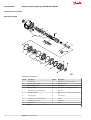
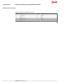
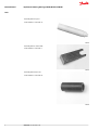
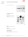
MAKING MODERN LIVING POSSIBLE Service Manual Steering Unit Type OSPB, OSPC and OSPF powersolutions.danfoss.com Service Manual Hydrostatic Steering Unit Type OSPB, OSPC and OSPF Revision History Table of Revisions 2 Date Changed Rev Mar 2014 Converted to Danfoss layout - DITA CMS CA Aug 2011 Drawing BG May 2011 Hexagon size BF Sep 2010 New back cover BE Jan 2010 Japan location BD Dec 2008 Tightening torque changed BC 520L0066 • Rev CA • Mar 2014 Service Manual Hydrostatic Steering Unit Type OSPB, OSPC and OSPF Contents Exploded View and Seal Kit Tools Dismantling Assembly Exploded View OSPB....................................................................................................................................................................... 4 Exploded View OSPC / OSPF.........................................................................................................................................................5 Tools...................................................................................................................................................................................................... 7 Dismantling......................................................................................................................................................................................10 Dismantling the pressure relief valve for OSPC.................................................................................................................. 16 Dismantling................................................................................................................................................................................ 16 Dismantling the pressure relief valve ...............................................................................................................................18 Cleaning....................................................................................................................................................................................... 18 Lubrication.................................................................................................................................................................................. 18 Inspection and Replacement................................................................................................................................................18 Assembling.......................................................................................................................................................................................19 Assemble spool and sleeve...................................................................................................................................................20 OSPB LS, OSPBX LS, OSPC LS, OSPC LSR and OSPF...................................................................................................... 20 OSPB CN and OSPC CN........................................................................................................................................................... 20 Assembly Pattern for Bearings.................................................................................................................................................. 22 Assembling Pattern for Standard Bearing....................................................................................................................... 22 Assembly Pattern for Double Bearing...............................................................................................................................22 Installation Instructions for O-ring / Kin-ring / Roto glyd................................................................................................23 Installation Instructions for Lip Seal........................................................................................................................................ 24 Assembly of the Pressure Relief Valve for OSPC................................................................................................................. 31 Assambly of the Shock Valves for OSPC/OSPC LS/OSPC LSR......................................................................................... 32 Maximum Tightening Torque and Hydraulic Connections Maximum Tightening Torque and Hydraulic Connections............................................................................................ 35 520L0066 • Rev CA • Mar 2014 3 Service Manual Hydrostatic Steering Unit Type OSPB, OSPC and OSPF Exploded View and Seal Kit Exploded View OSPB Exploded View OSPB Callouts Callout 4 Description Callout Description 1 Dust seal ring 15 O-ring 80,5 • 1,5 mm [3.17 • 0.06 in] 2 Housing + spool + sleeve 16 Distributor plate 3 Ball 8.5 mm [0.33 in] 17 Gearwheel 4 Thread bushing 18 O-ring 75.92 • 1,78 mm [2.99 • 0.07 in] 5 O-ring with kin-ring or Roto Glyd 19 End cover 7 Bearing assembly 20 Washer 8.2 • 11,9 • 1.0 mm [0.32 • 0.47 • 0.04 in] 10 Ring for springs 22 Special screw 11 Cross pin 6 • 41 mm [0.24 • 1.61 in] 23 Screw 12 Neutral position springs 24 Name label 13 Cardan shaft 26 Spacer 14 Spacer 520L0066 • Rev CA • Mar 2014 Service Manual Hydrostatic Steering Unit Type OSPB, OSPC and OSPF Exploded View and Seal Kit Exploded View OSPC / OSPF Exploded View OSPC / OSPF Callouts Callout Description Callout Description 1 Dust seal ring 19 End cover 2 Housing, spool and sleeve. Check valve and the seats for relief and shock valves are locktited. 20 Washer 3 Ball 8.5 mm [0.33 in] 22 Special screw 4 Thread bushing 23 Screw 5 O-ring used with kin-ring (item 6) 24 Name plate 6 Kin-ring 30 Complete relief valve 7 Bearing assembly 31 Spring wire 10 Ring 32 Complete shock valve 11 Cross pin 33 Ball 3/16 in 14 Spacer 38 Spring 13 Cardan shaft 34 Rolled pin 520L0066 • Rev CA • Mar 2014 5 Service Manual Hydrostatic Steering Unit Type OSPB, OSPC and OSPF Exploded View and Seal Kit Exploded View OSPC / OSPF Callouts (continued) 6 Callout Description Callout Description 12 Set of springs 36 Bushing 15 O-ring 35 Ball 16 Distributor plate 39 Kin ring 17 Gearwheel set 40 O-ring 18 O-ring 520L0066 • Rev CA • Mar 2014 Service Manual Hydrostatic Steering Unit Type OSPB, OSPC and OSPF Tools Tools Holding tool Code number: SJ 150-9000-2 Guide ring Code number: SJ 150-9000-16 Assembly tool for O-ring and kin-ring / Roto Glyd Code number: SJ 150-9000-11 Code number: SJ 150N4014-1 520L0066 • Rev CA • Mar 2014 7 Service Manual Hydrostatic Steering Unit Type OSPB, OSPC and OSPF Tools Assembly tool for lip seal Code number: SJ 150-9000-17 Assembly tool for cardan shaft. Code number: SJ 150-9000-3 Assembly tool for dust seal. Code number: SJ 150-9000-22 8 520L0066 • Rev CA • Mar 2014 Service Manual Hydrostatic Steering Unit Type OSPB, OSPC and OSPF Tools Torque wrench 0 - 70 N.m. 13 mm socket spanner. 6.8 and 12 mm sockets. 12 mm screwdriver. 2 mm [0.08 in] screwdriver. 13 mmring spanner. 6.8 and 12 mm socket spanners. Plastic hammer. Tweezers. The tools are not available from Danfoss 520L0066 • Rev CA • Mar 2014 9 Service Manual Hydrostatic Steering Unit Type OSPB, OSPC and OSPF Dismantling Dismantling Dismantle steering column from steering unit and place the steering unit in the holding tool. Screw out the screws in the end cover (6-off plus one special screw). Remove the end cover, sideways. Lift the gearwheel set (with spacer if fitted) off the unit. Take aut the two O-rings. 10 520L0066 • Rev CA • Mar 2014 Service Manual Hydrostatic Steering Unit Type OSPB, OSPC and OSPF Dismantling Remove the cardan shaft Remove distributor plate. Screw out the threaded bush over the check valve. 520L0066 • Rev CA • Mar 2014 11 Service Manual Hydrostatic Steering Unit Type OSPB, OSPC and OSPF Dismantling Remove O-ring OSPB, OSPB LS, OSPBX LS: Shake out the check valve ball (∅8 mm) OSPC LS, OSPC LSR: Shake out the check valve ball and suction valve pins and balls. On some pins in the OSPC there are two springs (see page 4, pos. 38). Replace this pins prior to the reassembly! Take care to keep the cross pin in the sleeve and spool horizontal. The pin can be seen through the open end of the spool. Press the spool inwards and the sleeve, ring, bearing races and needle bearing will be pushed out of the housing together. 12 520L0066 • Rev CA • Mar 2014 Service Manual Hydrostatic Steering Unit Type OSPB, OSPC and OSPF Dismantling Take ring, bearing races and needle bearing from sleeve and spool. The outer (thin) bearing race can sometimes “stick” in the housing, therefore check that it has come out. Press out the cross pin. Use the special screw from the end cover. Note next point/paragraph! OSPB CN and OSPC CN CN A small mark has been made with a pumice stone on both spool and sleeve close to one of the slots for the neutral position springs (see drawing). If the mark is not visible, remember to leave a mark of your own on sleeve and spool before the neutral position springs are dismantled. For OSPF both marks should be placed opposite each other! 520L0066 • Rev CA • Mar 2014 13 Service Manual Hydrostatic Steering Unit Type OSPB, OSPC and OSPF Dismantling OSPF Carefully press the spool out of the sleeve. Press the neutral position springs out of their slots in the spool. 14 520L0066 • Rev CA • Mar 2014 Service Manual Hydrostatic Steering Unit Type OSPB, OSPC and OSPF Dismantling Remove dust seal and O-ring / Kin-ring / Roto Glyd. Remove plugs from shock valves using a 6 mm hexagon socket spanner Remove seal washers (2-off). 520L0066 • Rev CA • Mar 2014 15 Service Manual Hydrostatic Steering Unit Type OSPB, OSPC and OSPF Dismantling Unscrew the setting screws using a 6 mm hexagon socket spanner. Shake out the two springs and two valve balls into your hand. The valve seats are bonded into the housing and cannot be removed. The shock valves are now dismantled. Dismantling the pressure relief valve for OSPC Dismantling Dismantling the Pressure Relief Valve for OSPC 16 520L0066 • Rev CA • Mar 2014 Service Manual Hydrostatic Steering Unit Type OSPB, OSPC and OSPF Dismantling Screw out the plug using and 8 mm hexagon socket spanner. Remove seal washers . Unscrew the setting screw using an 6 mm hexagon socket spanner. Shake out spring and piston. The valve seat is bonded into the housing and cannot be removed. 520L0066 • Rev CA • Mar 2014 17 Service Manual Hydrostatic Steering Unit Type OSPB, OSPC and OSPF Dismantling The pressure relief valve is now dismantled. Dismantling the pressure relief valve Dismantling OSPC The steering unit OSPC is now completely dismantled. Replace this pins prior to the reassembly! Cleaning Clean all parts carefully in Shellsol K or the like. Lubrication Before assembly, lubricate all parts with hydraulic oil. Inspection and Replacement Replace all seals and washers. Check all parts carefully and make any replacements necessary. 18 520L0066 • Rev CA • Mar 2014 Service Manual Hydrostatic Steering Unit Type OSPB, OSPC and OSPF Assembly Assembling Place the two flat neutral position springs in the slot. Place the curved springs between the flat ones and press them into place. Line up the spring set. 520L0066 • Rev CA • Mar 2014 19 Service Manual Hydrostatic Steering Unit Type OSPB, OSPC and OSPF Assembly Guide the spool into the sleeve. Make sure that spool and sleeve for OSPB LS, OSPBX LS, OSPC LS, OSPC LSR and OSPF are placed correctly in relation to each other (see page 10). Assemble spool and sleeve OSPB LS, OSPBX LS, OSPC LS, OSPC LSR and OSPF When assembling spool and sleeveonly one of two possible ways of positioning the spring slots is correct. There are three slots in the spool and three holes in the sleeve in the end of the spool/sleeve opposite to the end with spring slots. Place the slots and holes opposite each other so that parts of the holes in the sleeve are visible through the slots in the spool. OSPB CN and OSPC CN Assemble the spool/sleeve and make sure the marks on spool and sleeve are opposite each other Dismantling for more information. 20 520L0066 • Rev CA • Mar 2014 Service Manual Hydrostatic Steering Unit Type OSPB, OSPC and OSPF Assembly Press the springs together and push the neutral position springs into place in the slave. Line up the springs and centre them. Guide the ring down over the sleeve. The ring should be able to move - free of springs. Fit the cross pin into the spool/sleeve. 520L0066 • Rev CA • Mar 2014 21 Service Manual Hydrostatic Steering Unit Type OSPB, OSPC and OSPF Assembly Fit bearing races and needle bearings as shown on the drawing next page. Assembly Pattern for Bearings Assembling Pattern for Standard Bearing 1. Outer bearing race 2. Needlebearing 3. Inner bearing race 4. Spool 5. Sleeve Assembly Pattern for Double Bearing 1. Washer for axial bearing 2. Outer needlebearing 22 520L0066 • Rev CA • Mar 2014 Service Manual Hydrostatic Steering Unit Type OSPB, OSPC and OSPF Assembly 3. Outer bearing race 4. Spool 5. Sleeve 6. Inner needlebearing 7. Inner bearing race The inside chamfer on the inner bearing race must face the inner spool. Installation Instructions for O-ring / Kin-ring / Roto glyd Turn the steering unit until the bore is horizontal. Guide the outer part of the assembly tool into the bore for the spool/sleeve. Grease o-ring and king-ring/roto Glyd with hydraulic oil and place them on the tool. Hold the outer part of the assembly tool in the bottom of the steering unit housing and guide the inner part of the tool right to the bottom. 520L0066 • Rev CA • Mar 2014 23 Service Manual Hydrostatic Steering Unit Type OSPB, OSPC and OSPF Assembly Press and turn the o-ring/kin-ring into position in the housing. Draw the inner and outer parts of the assembly tool out of the steering unit bore, leaving the guide from the inner part in the bore. Installation Instructions for Lip Seal Lubricate the lip seal with hydraulic oil and place it on the assembly tool. 24 520L0066 • Rev CA • Mar 2014 Service Manual Hydrostatic Steering Unit Type OSPB, OSPC and OSPF Assembly Guide the assembly tool right to the bottom. Press and turn the lip seal into place in the housing. With a light turning movement, guide the spool and sleeve into the bore. Fit the spool set holding the cross pin horizontal. 520L0066 • Rev CA • Mar 2014 25 Service Manual Hydrostatic Steering Unit Type OSPB, OSPC and OSPF Assembly The spool set will push out the assembly tool guide. The o-ring and kin-ring/roto Glyd are now in position. Turn the stearing unit until the bore is vertical again. Put the check valve ball into the hole indicated by the arrow. Screw the threaded bush lightly into the check valve bore. The top of the bush must lie just below the surface of the housing. 26 520L0066 • Rev CA • Mar 2014 Service Manual Hydrostatic Steering Unit Type OSPB, OSPC and OSPF Assembly Place a ball in the two holes indicated by the arrows. Place a new pin in the same two holes. In some cases a spring has to be fitted (see page 4 pos. 38) on the pin before it is placed in the housing. 520L0066 • Rev CA • Mar 2014 27 Service Manual Hydrostatic Steering Unit Type OSPB, OSPC and OSPF Assembly Grease the o-ring with mineral oil approx. viscosity 500 mm2/s [SUS] at 20°C [68 °F]. Place the distributor plate so that the channel holes match the holes in the housing. Guide the cardan shaft down into the bore so that the slot is parallel with the connection flange. 28 520L0066 • Rev CA • Mar 2014 Service Manual Hydrostatic Steering Unit Type OSPB, OSPC and OSPF Assembly Place the cardan shaft as shown - so that it is held in position by the mounting fork. Grease the two o-rings with mineral oil approx. viscosity 500 mm2/s [SUS] at 20°C [°F] and place them in the two grooves in the gear rim. Fit the gearwheel and rim on the cardan shaft. C Caution Fit the gearwheel (rotor) and cardan shaft so that a tooth base in the rotor is positioned in relation to the shaft slot as shown. Turn the gear rim so that the seven trough holes match the holes in the housing. 520L0066 • Rev CA • Mar 2014 29 Service Manual Hydrostatic Steering Unit Type OSPB, OSPC and OSPF Assembly Fit the spacer, if any. Place the end cover in position. Fit the special screw with washer and place it in the hole shown. 30 520L0066 • Rev CA • Mar 2014 Service Manual Hydrostatic Steering Unit Type OSPB, OSPC and OSPF Assembly Fit the six screws with washers and insert them. Cross-tighten all the screws and the rolled pin with a torque of 30 +/-6 N.m [265.5 +/- 53 lbf.in]. The OSPB, OSPB LS and OSPBX LS can now be function tested. Assembly of the Pressure Relief Valve for OSPC Fit the piston. Fit the spring 520L0066 • Rev CA • Mar 2014 31 Service Manual Hydrostatic Steering Unit Type OSPB, OSPC and OSPF Assembly Screw in the setting screw with an 8 mm hexagon socket spanner. Make the pressure setting on a panel or the vehicle. Screw plug with dust seal into the housing using an 8 mm hexagon socket spanner. Tightening torque: 65 +/-5 N.m. [575.3 +/- 44.2 lbf.in] Assambly of the Shock Valves for OSPC/OSPC LS/OSPC LSR Put a ball in the two holes indicated by the arrows. 32 520L0066 • Rev CA • Mar 2014 Service Manual Hydrostatic Steering Unit Type OSPB, OSPC and OSPF Assembly Place springs and valve cones over the two balls. The blue spring applies to setting range 90-180 bar [1305-2610 psi]. The untreated spring applies to setting range 170-260 bar [2465-3770 psi] Screw in the two setting screws using a 6 mm hexagon socket spanner. Make the pressure setting on a panel or the vehicle. Screw plug with seal ring into the two shock valves and tighten them with a torque of : 30 +10 N.m [265.5 + 88.5 lbf.in] using a 6 mm Ihexagon socket spanner. Steering unit type OSPC, OSPC LS or OSPC LSR is now assembled. 520L0066 • Rev CA • Mar 2014 33 Service Manual Hydrostatic Steering Unit Type OSPB, OSPC and OSPF Assembly Place the dust seal ring in the housing. With the OSPC, OSPC LS and OSPC LSR the dust seal ring must be placed only after the pressure relief valve and shock valves have been fitted. Fit the dust seal ring in the housing using special tool SJ 150-9000-22 (see page 5) and a plastic hammer. Press the plastic plugs into the connection ports. Do not use a hammer! 34 520L0066 • Rev CA • Mar 2014 Service Manual Hydrostatic Steering Unit Type OSPB, OSPC and OSPF Maximum Tightening Torque and Hydraulic Connections Maximum Tightening Torque and Hydraulic Connections Maximum Tightening Torque and Hydraulic Connections T: Tank L: Left port P: Pump R: Right port Screwed connection Maximum tightening torque N.m [lbf.in] With cutting edge With cooper washer With aluminium washer With O-ring G 1/4 35 [309] 35 [309] 35 [309] - G 3/8 70 [619] 45 [398] 50 [442] - G 1/2 100 [885] 55 [486] 80 [708] - 7/16 -20 UNF - - - 20 [177] 3/4 -16 UNF - - - 60 [531] M 12 • 1.5 30 [265] 20 [177] 30 [265] 25 [221] M18 • 1.5 80 [708] 55 [486] 70 [619] 50 [442] M22 • 1.5 100 [885] 65 [575] 80 [708] 60 [531] 520L0066 • Rev CA • Mar 2014 35 Products we offer: • Bent Axis Motors • Closed Circuit Axial Piston Danfoss Power Solutions is a global manufacturer and supplier of high-quality hydraulic and electronic components. We specialize in providing state-of-the-art technology and solutions that excel in the harsh operating conditions of the mobile off-highway market. Building on our extensive applications expertise, we work closely with our customers to ensure exceptional performance for a broad range of off-highway vehicles. • Displays • Electrohydraulic Power We help OEMs around the world speed up system development, reduce costs and bring vehicles to market faster. Danfoss – Your Strongest Partner in Mobile Hydraulics. Pumps and Motors Steering • • • • Electrohydraulics Go to www.powersolutions.danfoss.com for further product information. Hydraulic Power Steering Wherever off-highway vehicles are at work, so is Danfoss. Integrated Systems We offer expert worldwide support for our customers, ensuring the best possible solutions for outstanding performance. And with an extensive network of Global Service Partners, we also provide comprehensive global service for all of our components. Joysticks and Control Handles • Microcontrollers and Please contact the Danfoss Power Solution representative nearest you. Software • Open Circuit Axial Piston Pumps • • • • • • Orbital Motors PLUS+1® GUIDE Proportional Valves Sensors Steering Transit Mixer Drives Comatrol www.comatrol.com Schwarzmüller-Inverter www.schwarzmuellerinverter.com Local address: Turolla www.turollaocg.com Valmova www.valmova.com Hydro-Gear www.hydro-gear.com Daikin-Sauer-Danfoss www.daikin-sauer-danfoss.com Danfoss Power Solutions US Company 2800 East 13th Street Ames, IA 50010, USA Phone: +1 515 239 6000 Danfoss Power Solutions GmbH & Co. OHG Krokamp 35 D-24539 Neumünster, Germany Phone: +49 4321 871 0 Danfoss Power Solutions ApS Nordborgvej 81 DK-6430 Nordborg, Denmark Phone: +45 7488 2222 Danfoss Power Solutions (Shanghai) Co. Ltd. Building #22, No. 1000 Jin Hai Rd Jin Qiao, Pudong New District Shanghai, China 201206 Phone: +86 21 3418 5200 Danfoss can accept no responsibility for possible errors in catalogues, brochures and other printed material. Danfoss reserves the right to alter its products without notice. This also applies to products already on order provided that such alterations can be made without subsequential changes being necessary in specifications already agreed. All trademarks in this material are property of the respective companies. Danfoss and the Danfoss logotype are trademarks of Danfoss A/S. All rights reserved. 520L0066 • Rev CA • Mar 2014 www.danfoss.com © Danfoss A/S, 2014