1
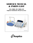
AIR TECHNIQUES INTERNATIONAL
A Division of Hamilton Associates, Inc.
11403 Cronridge Drive • Owings Mills, MD 21117-2247 USA • Tel 410.363.9696 • Fax 410.363.9695
http://www.atitest.com
1800213
SERVICE MANUAL
5C GENERATOR
P/N:
9300207
9300208
9300213
9300214
Page 1 of 33
1800213 Rev B 05-10-10
AIR TECHNIQUES INTERNATIONAL
A Division of Hamilton Associates, Inc.
11403 Cronridge Drive • Owings Mills, MD 21117-2247 USA • Tel 410.363.9696 • Fax 410.363.9695
http://www.atitest.com
TABLE OF CONTENTS
I.
SCOPE ...................................................................................................... 3
II. FUNCTIONAL DESCRIPTION................................................................... 4
III. PREVENTATIVE and PERIODIC MAINTENANCE.................................... 8
IV. SERVICE REPAIR..................................................................................... 9
V. SPARE PARTS LIST ............................................................................... 11
VI. FINAL INSPECTION CHECK LIST .......................................................... 12
VII. TESTING and ADJUSTMENT ................................................................. 13
APPENDIX 1 – SERVICE and REPAIR TROUBLESHOOTING PROCEDURES
...................................................................................................................... 22
APPENDIX 2 –
ASSEMBLY DRAWINGS ................................................... 24
Page 2 of 33
1800213 Rev B 05-10-10
AIR TECHNIQUES INTERNATIONAL
A Division of Hamilton Associates, Inc.
11403 Cronridge Drive • Owings Mills, MD 21117-2247 USA • Tel 410.363.9696 • Fax 410.363.9695
http://www.atitest.com
I.
SCOPE
The purpose of this document is to provide authorized service personnel with information necessary
to service, repair and test the 5C Aerosol Generator. This document is intended to be used in
conjunction with information found in the Documents List below
In the event that two documents contain conflicting information or instructions, the document with the
highest authority shall be considered correct. The order of precedence is provided in the Documents
List.
Document List:
The following documents shall be used in addition to following the instructions in this procedure:
•
•
•
•
•
•
HA Drawing 0200341
Complete Bill of Material for 0200341 in Decade
HA Drawing 1700173 Electrical Schematic
Final Assembly and Test Procedures IAT-106-WI, IAT-107-WI, IAT-108-WI, OR IAT-109-WI
(whichever applies)
5C Test and Acceptance Record Doc. IAT-110- FM
5C Operators and Maintenance Manual Part Number 1600806
REVISION HISTORY
REVISION
0
1
A
B
DATE
07/09
08/09
08/09
05/10
CHANGES
Draft for Review
2nd Draft for Review
Initial Release
Alarm temperature changed to 30 deg. C. Thermal Cut-out Switch
temperature changed to 148 deg. C. Revise/update test procedures
Page 3 of 33
1800213 Rev B 05-10-10
AIR TECHNIQUES INTERNATIONAL
A Division of Hamilton Associates, Inc.
11403 Cronridge Drive • Owings Mills, MD 21117-2247 USA • Tel 410.363.9696 • Fax 410.363.9695
http://www.atitest.com
II.
FUNCTIONAL DESCRIPTION
The 5C uses heat to vaporize liquid aerosol reagent under an inert gas flow to produce aerosol. To
achieve this, the heater block is required to be heated to 407°C. Inert gas must be used in this
process. There are several conditions that must be met in order for the 5C to able to produce
aerosol:
•
•
•
•
•
•
•
The 5C must have electrical power,
The main power switch must be ON,
The temperature controller must indicate a temperature between 337 and 437ºC,
Adequate inert gas must be flowing through the generator,
The aerosol switch must be ON, AND
The metering valve must be open.
The generator must be placed on a level, stable surface.
If any one of these conditions is not met, the 5C will not produce aerosol.
The 5C has several internal protection devices. These devices, if active will prevent the 5C from
producing aerosol since they affect the conditions listed above.
A.
Part Numbers
There are four top level part numbers associated with 5C generators. The part numbers correspond
to the following:
•
•
•
•
Part Number 9300207 for 115 VAC and uses PAO-4*
Part Number 9300208 for 230 VAC and uses PAO-4*
Part Number 9300213 for 115 VAC and uses DOP
Part Number 9300214 for 230 VAC and uses DOP
*Part numbers 9300207 and 9300208 can also be used with DOS (DEHS), Ondina El, or mineral oil
as an aerosol reagent.
Before starting repairs, note the part number on the product label for the proper voltage and liquid
aerosol reagent.
B.
Electrical System
The 5C will operate at either 115 VAC or 230 VAC rating. The only physical difference is the
installation of the two fuses and the fuse holder inside the Power Entry Module. Incorrectly setting
up the fuses will produce the following:
•
Powering a 115 V fused unit with 230 V will overheat the transformer and open the
transformer’s protective thermal switches. If the switches open, power to the heater
cartridges will cease and the generator must cool down until the switches re-set.
Page 4 of 33
1800213 Rev B 05-10-10
AIR TECHNIQUES INTERNATIONAL
A Division of Hamilton Associates, Inc.
11403 Cronridge Drive • Owings Mills, MD 21117-2247 USA • Tel 410.363.9696 • Fax 410.363.9695
http://www.atitest.com
•
1.
Powering a 230 V fused unit with 115 V will under power the heater cartridges and the
temperature controller will show a slow rise in the temperature. Normally it would take 20
minutes for the temperature to reach the correct level. Under this condition it will take more
than an hour.
Transformer
The 5C uses a transformer to convert line AC voltage to low (12 VAC) to power the two
mechanical relays. The transformer mounted on the circuit board is protected from high
temperature (caused by incorrect line voltage) by two thermal cut-outs. The cut-outs are
located on top of the primary coil and connected to the circuit board. If there is a short failure
at the transformer or if the fuses are configured for 115 V and 230 V power is applied, the cutouts will open and break power to the transformer. The cut-outs are set to 70ºC. Once the
transformer cools sufficiently, the cut-outs self reset. The temperature controller will not be
able to reach the operating temperature because the transformer will not stay functional long
enough (see relays). Therefore the failure will be noticeable at the temperature controller
display.
Transformer output of 12 VAC can be verified and measured across the two test points on the
PCB. When measuring the transformer voltage the PCB assembly must be held vertical in
order to keep the tipping switched closed (see tipping switch).
2.
Relays
The 5C uses two mechanical relays to power the heater cartridges with high AC power. If
either high or low power drops out, the relays will open and the heater cartridges will not be
powered.
3.
Solenoid Valve
The 12 V solenoid normally closed valve controls gas flow to the liquid piloting valve. When
energized, the valve opens and allows gas to pressurize the piloting valve which then allows
liquid flow to the heater block. The solenoid valve is energized by switching the Aerosol
Switch to ON while low 12 VAC power is available. The solenoid valve is a three-way valve
that vents when de-energized. Therefore, when the solenoid valve is de-energized the
piloting valve closes the liquid feed.
C.
Gas Flow
Gas flow is controlled at the source (bottle) by the operator. Once the source is connected to the 5C,
and the gas turned on, gas will flow through the generator. Purging is constant unless the gas is
turned off at the source.
The inert gas line or tube is connected to the ¼ inch outer diameter tube fitting at the front panel.
Gas flow is initially regulated to 50 psi (3.45 bar) at the source. If regulation is above 65 psi (4.5 bar),
the internal pressure relief valve will open. This protects the 5C from excessive pressure to the
regulator (see Internal Protective Devices).
Page 5 of 33
1800213 Rev B 05-10-10
AIR TECHNIQUES INTERNATIONAL
A Division of Hamilton Associates, Inc.
11403 Cronridge Drive • Owings Mills, MD 21117-2247 USA • Tel 410.363.9696 • Fax 410.363.9695
http://www.atitest.com
D.
Regulator
At the gas input, a pressure regulator is set to allow flow in the tank and heater block. Enough flow is
required to pressurize the tank so liquid will flow and to actuate the piloting actuator (see Liquid Feed
Valve). If there is excessive flow, the aerosol will be too wet. The regulator is set to maintain dry
aerosol at the output nozzle.
Gas flow is routed to the tank and to the solenoid valve input port. When all conditions are met the
solenoid valve has ON/OFF control by the aerosol switch. When energized, gas is allowed to pilot
the liquid feed actuator which then allows the liquid feed valve to open and liquid flow to the heater
block.
E.
Internal Protective Devices
1. High Pressure Relief Valve - At the gas input the 5C has a high pressure relief valve set to
open at 65 Psi (4.5 bar). If the gas source regulator is set higher than 65 psi (4.5 bar), the
valve will open and relieve excess pressure. This feature protects the internal pneumatic
components and the liquid reservoir.
2. Low Pressure Relief Valve - Mounted at the internal regulator is a low pressure relief valve
set at 6.8 psi (0.47 bar). Should the internal regulator be set too high or fail to regulate the
gas to the proper pressure, the valve will open and relieve flow to the reservoir. Normally the
internal regulator is set much lower (approximately 2-3 psi) (0.14 to 0.2 bar).
3. Thermal Cut-out Switch - A thermal cut-out switch is mounted on top of the heater block
metal panel. The thermal cut-out switch senses the temperature of the heater panel surface
and is set to open at 148ºC. If the panel surface exceeds 148ºC the switch opens and breaks
power to the mechanical relays. The temperature at the controller will drop at this point. The
switch has a manual reset button at the top. The surface temperature will have to cool
enough to allow the switch to be re-set. Once re-set the heaters can be powered, however an
investigation as why the switch opened should be conducted prior to re-setting
4. Tipping Switch - The tipping switch is mounted to the PCB. The switch opens when the 5C
is tipped over in any orientation more than 30º from horizontal. When the switch opens, 12
VAC power is interrupted causing the mechanical relays to open and the solenoid valve to
close. This effectively turns off the aerosol and power to the heater cartridges. If the switch
closes by setting the 5C back to level position, the unit will normalize. An indicator of the
tipping switch opening and closing is the aerosol switch green LED turning on and off when
the switch is left on (see Aerosol Switch).
F.
In-line filters
There are two 40 micron fluid in-line filters in the 5C. The first is at the gas input between the high
pressure relief valve and the internal regulator. This filters out impurities from the inert gas source.
Page 6 of 33
1800213 Rev B 05-10-10
AIR TECHNIQUES INTERNATIONAL
A Division of Hamilton Associates, Inc.
11403 Cronridge Drive • Owings Mills, MD 21117-2247 USA • Tel 410.363.9696 • Fax 410.363.9695
http://www.atitest.com
The second filter is located at the liquid feed line between the reservoir and the concentration
metering valve. This filter prevents impurities in the liquid from reaching the metering valve or heater
block. If problems are occurring with aerosol production or low concentration is noticed, the filters
should be inspected or changed.
G.
Aerosol Switch
The aerosol switch located on the front control panel, controls aerosol production ON and OFF. The
switch is functional only when all the conditions for aerosol production are met. The switch can be
used before or after setting the metering valve. Once the metering valve is set, the switch provides
ON/OFF control of aerosol production without changing concentration.
If the low 12 V power (see transformer) is functional, the LED will illuminate when the switch is ON. If
the switch does not illuminate the switch assembly or the transformer has malfunctioned.
H.
Liquid Feed Valve
The Liquid Feed Valve controls liquid flow from the metering valve to the heater block. The liquid
feed valve is gas pressure piloted controlled. A piloting actuator activates the liquid feed valve when
gas pressure is applied. When liquid flow is needed, the aerosol switch turns on the solenoid valve
which then pilots the liquid feed valve. Therefore no liquid flow will occur if the gas pressure is too
low or the solenoid valve is de-energized (see solenoid valve).
I.
Temperature Controller (OMRON E5CSV-R1T)
The temperature controller is set up to indicate temperature in degrees Celsius. The set point is
407ºC. The 5C uses the controller’s alarm relay output to allow the solenoid valve to open and allow
liquid flow. The alarm is set to output at 30ºC above and below the set point temperature. The
controller must therefore indicate a temperature between 377 and 437ºC before the solenoid valve
can be energized.
If inspecting or replacing the temperature controller, refer to the set-up procedure in Section V.
J.
Output Collar
The output collar has a perforated tube between the collar and the rear panel. The perforations
provide quench air to the aerosol stream. The design allows the operator to clamp an un-vented
hose to the output collar and maintain quench air to the vapor stream.
Page 7 of 33
1800213 Rev B 05-10-10
AIR TECHNIQUES INTERNATIONAL
A Division of Hamilton Associates, Inc.
11403 Cronridge Drive • Owings Mills, MD 21117-2247 USA • Tel 410.363.9696 • Fax 410.363.9695
http://www.atitest.com
III. PREVENTATIVE and PERIODIC MAINTENANCE
!
Warning – Electrical Hazard
UNPLUG POWER CORD FROM UNIT BEFORE REMOVING THE
TOP COVER OR ATTEMPTING INSPECTION OR SERVICE
It is recommended that customers return their 5C for annual inspection and service. At a
minimum, the following should be performed when receiving a 5C for this service:
1. Remove the top panel and visually inspect the interior for signs of cable and tubing distress
(fraying, kinking, heat, brittleness, etc.), liquid build-up, and corrosion.
2. Replace cables or tubing sections that are damaged or distressed.
3. Clean/wipe excess liquid buildup from interior.
4. Check and inspect condition of fuses. Install new fuses as necessary.
5. Check condition of the fill cap for cracks and missing or damaged gasket.
6. Inspect the output nozzle orifice for signs of blockage. Use a 0.060 ±0.002 inch (1.5 mm ±
0.05 mm) diameter metal pin or wire to clean out the blockage.
7. Inspect the heater block fittings for wetness, looseness or cracks in the insulation blocks. If
needed, remove the heater block assembly from the back panel and inspect for further signs
of damage.
8. Check for loose or missing hardware. Tighten as necessary or replace any missing hardware.
9. Perform electrical safety, mechanical and aerosol test per in Section VII.
Page 8 of 33
1800213 Rev B 05-10-10
AIR TECHNIQUES INTERNATIONAL
A Division of Hamilton Associates, Inc.
11403 Cronridge Drive • Owings Mills, MD 21117-2247 USA • Tel 410.363.9696 • Fax 410.363.9695
http://www.atitest.com
IV. SERVICE REPAIR
!
Warning – Burn Hazard
HEATER BLOCK BECOMES HOT – DO NOT TOUCH
After inspection and/or repair is performed, turn the unit ON and allow it get to the operating
temperature of 407º C. Note the time required to reach the operating temperature. If it takes more
than 25 minutes, or temperature fails to reach the operating temperature consult the Troubleshooting
Guide in Appendix 1.
A.
B.
Basic Instructions:
•
Apply three wraps of ¼” wide (6.3 mm) commercial grade Teflon tape for sealing all NPT
threads. Apply to male NPT threads in a clockwise direction with the threads facing you
before installing.
•
Note direction of arrows on filters and check valve. These components must be oriented in
the correct direction as indicated on the exploded views.
•
No special or custom tools are required for repair service. However there is special test
equipment required for post-repair testing.
•
Refer to the assembly exploded views in Appendix X for disassembly and replacement of
components. If necessary use the trouble-shooting guide to identify a problem with a unit.
•
All repairs require re-testing. See Section VII
Front Panel (PN 0600434)
The front panel contains electrical components that may require replacement if damaged by external
means. The front panel also contains the pneumatic assembly components
C.
Rear Panel (PN 0600435)
1. The rear panel contains the heater assembly PN 0600430 and the output collar assembly.
2. Inspect output collar (items 6 through 11) for looseness. Tighten hardware as necessary.
D.
Heater Assembly (PN 0600430)
1. Remove heater block assembly from rear panel. Save all hardware.
Page 9 of 33
1800213 Rev B 05-10-10
AIR TECHNIQUES INTERNATIONAL
A Division of Hamilton Associates, Inc.
11403 Cronridge Drive • Owings Mills, MD 21117-2247 USA • Tel 410.363.9696 • Fax 410.363.9695
http://www.atitest.com
2. Inspect insulation blocks (items 11 and 12) for cracks.
3. If necessary to replace insulation blocks, disassemble the heater.
4. Replace insulation pads (items 9 and 10) if they are wet or contaminated
E.
Heater Block Assembly (PN 0600430)
1. If heater block fittings are to be removed or replaced, clean threads of all residue. Discard old
washers (part number T5A0-0272) and replace with new washers. Use Resbond 907TS high
temperature thread locking compound when assembling heater block fittings. Check the shelf
life expiration date on the Resbond 907TS container. Only use a container that has not
expired.
2. Tighten heater block fittings to 70 to 80 ft. lbs (9.7 kg/m to 11 kg/m) torque.
3. Inspect thermocouple cable for thermal stress or fraying. Replace if needed.
F.
Metering Valve Assembly (PN 0600433)
1. Remove the metering valve assembly from the front panel. Save all hardware.
2. Disconnect tubing from fittings.
3. Remove the piloting actuator (item 2) and inspect the feed valve (item 3) plunger for ease of
movement. If the valve is sticking replace the valve.
4. Remove and replace the in-line 40 micron filter (item 1).
G.
Regulator Assembly (PN 0600432)
1. Remove the regulator valve assembly from the front panel. Save all hardware.
2. Disconnect tubing from fittings.
3. Remove and replace the in-line 40 micron filter (item 1).
Page 10 of 33
1800213 Rev B 05-10-10
AIR TECHNIQUES INTERNATIONAL
A Division of Hamilton Associates, Inc.
11403 Cronridge Drive • Owings Mills, MD 21117-2247 USA • Tel 410.363.9696 • Fax 410.363.9695
http://www.atitest.com
V. SPARE PARTS LIST
The follow list includes parts that are commonly used for maintenance or repair (refer to Appendix 2
for exploded views of the assemblies).
Description
Replacement Line Cord, 115V
Replacement Line Cord, 230V
Replacement Fill Cap
Operation and Maintenance Manual
Fuses, 115V
Fuses, 230V
Filter 40 Micron
Polyflow Tubing Black 44P-1/4
Drain Plug #4 SAE
Liquid Level Sight Tube (5 in.)
Heater rod and cable assy
Control PCB
Insulator Block Front
Insulator Block Rear
Liquid Fill Cap
Liquid Fill Cap Gasket
Part Number
6700179
6700180
3500123
1800206
6400112
6400111
5500162
5200100
5100875
5200116
6700165
0800186
1200290
1200291
3500123
T4B0-1368
Page 11 of 33
1800213 Rev B 05-10-10
AIR TECHNIQUES INTERNATIONAL
A Division of Hamilton Associates, Inc.
11403 Cronridge Drive • Owings Mills, MD 21117-2247 USA • Tel 410.363.9696 • Fax 410.363.9695
http://www.atitest.com
VI. FINAL INSPECTION CHECK LIST
The following inspections shall be performed after all service and repair work and before re-attaching
the top panel to the unit:
1. The output nozzle is clear of carbon build-up
2. Output collar hardware are securely fastened
3. The handle, foot pads and other hardware are securely fastened
4. All labels are legible and undamaged
5. Liquid level sight tube is clear and transparent
6. The fill cap gasket is intact and undamaged
7. No leaks around the tank drain plug
8. All electrical components are securely attached
9. There are no frayed wires on any cable
10. All wire connections are securely fastened (no loose terminals)
11. All pneumatic fitting connections are properly tightened
12. All pneumatic tubing is free of kinks or other distress
13. Test and adjust unit per Section VII
Page 12 of 33
1800213 Rev B 05-10-10
AIR TECHNIQUES INTERNATIONAL
A Division of Hamilton Associates, Inc.
11403 Cronridge Drive • Owings Mills, MD 21117-2247 USA • Tel 410.363.9696 • Fax 410.363.9695
http://www.atitest.com
VII. TESTING and ADJUSTMENT
!
1.
Warning – Electrical Hazard
RECEIVE TRAINING IN PROPER USE OF ELECTRICAL SAFETY
TEST EQUIPMENT AND TESTING AREA. STAY CLEAR OF UNIT
WHILE TEST IS IN PROCESS
Electrical Safety Tests (HiPot and Ground Bond Leakage)
1.1
•
Tools and Equipment Required
AC/DC HiPot with Insulation Resistance Tester, Quadcheck II Model 7564SA Electrical
Safety Compliance Analyzer or equal, with calibration.
a.
Set-Up
1
2.
Set up the AC/DC HiPot tester with insulation resistance tester:
Configure the tester as follows:
Test
System parameter
Parameter
PLC Remote
GPIB
LCD Contrast
Audible Alarm Volume
Fail Stop
Setting
OFF
08
6
4
ON
AC Dielectric
Voltage
Hi-Limit
Low Limit
Ramp time
Dwell time
Frequency
Arc Sense
Arc Fail
Scanner Set CH 1-16
Connect
1350V
25.00 mA
0.0 mA
2 sec.
5 sec.
60 Hz
1
OFF
00000000000000000
ON
Ground Bond
Current
Voltage
Hi-Limit
Lo-Limit
Dwell Time
Frequency
Scanner-CH
Offset
Connect
25.0 A
8V
100 milliohms
0 milliohms
2 sec.
60 Hz
0
0 milliohms
OFF
Page 13 of 33
1800213 Rev B 05-10-10
AIR TECHNIQUES INTERNATIONAL
A Division of Hamilton Associates, Inc.
11403 Cronridge Drive • Owings Mills, MD 21117-2247 USA • Tel 410.363.9696 • Fax 410.363.9695
http://www.atitest.com
NOTE: The 5C unit should be completely assembled including the top cover.
3.
Using the power cord that will be shipped with the unit, plug in 5C unit in at the main
power to the tester. See instruction sheet for connection method. For the chassis
return, connect to the Gas Inlet Port on the front panel.
Switch the 5C unit main power switch to ON.
4.
1.3
Test
With the tester configured and connected to the 5C, initiate the test by pressing the green button.
The tester will perform the AC Dielectric (Hi Pot) test first and Ground Bonding test last. The
tester will stop at the first failure. At green light will illuminate if the unit passes.
At completion of the test, record Pass/ Fail for each test and the resistance of the Ground Bond
test in milliohms on the Test and Acceptance Record.
2.
Mechanical Tests
2.1
•
•
•
•
•
•
•
•
•
•
•
•
•
Tools and Equipment Required
Small flathead screwdriver
7/16” spanner wrench
Brown test paper
Approximately 0.5 cup (118 cc) of liquid aerosol reagent (see part number for correct type)
High pressure Nitrogen inert gas @ 50psig +/-5 psig (3.45 bar ± 0.35 bar) (training
required)
Vacuum testing station (training required)
Long handled pliers or tongs
Stop watch
ATI test gauge no. ENG-20.
ATI test valve no. TF-AT5C-9300207
ATI test plug no. 2TF-AT5C-9300207
Heat air gun
Standard Volt-Ohm Multi-Meter (VOM)
2.2
Set-Up:
1. Remove the top panel part number 0600436, from the unit and save along with all the
hardware screws.
2. Remove ¼ inch tube ferrule from unit inert gas inlet and save ferrule for replacement at end of
all testing.
3. Fully close the test valve assembly (TF-AT5C-9300207) regulator and close the test valve.
4. Connect test valve regulator to shop air. Make sure the regulator gauge indicates zero
pressure.
5. Connect the end fitting of the test valve plastic tube to the gas inlet fitting at the font panel
(shown below).
Page 14 of 33
1800213 Rev B 05-10-10
AIR TECHNIQUES INTERNATIONAL
A Division of Hamilton Associates, Inc.
11403 Cronridge Drive • Owings Mills, MD 21117-2247 USA • Tel 410.363.9696 • Fax 410.363.9695
http://www.atitest.com
6. Using a 7/16” spanner wrench remove threaded fitting and plastic tube at the Tee at Point A
located as shown below.
7. Using a 7/16” spanner wrench connect the test gauge ENG-20 at the Tee fitting. When
reading pressure, hold the gauge vertical while reading as shown.
Page 15 of 33
1800213 Rev B 05-10-10
AIR TECHNIQUES INTERNATIONAL
A Division of Hamilton Associates, Inc.
11403 Cronridge Drive • Owings Mills, MD 21117-2247 USA • Tel 410.363.9696 • Fax 410.363.9695
http://www.atitest.com
2.3 High Pressure Test
1. Open the test valve.
2. Using the test valve regulator, SLOWLY increase the pressure until air begins to escape from
the high pressure relief valve inside the test unit.
3. Note the pressure on the test valve regulator when the air begins to escape. The pressure
shall be between 65 Psi (4.5 bar) and 80 Psi (5.5 bar).
4. Record Pass/Fail and the pressure on the Test and Acceptance Record.
5. Close the test valve and the regulator so that air is relieved and the pressure is zero.
2.4 Low Pressure Test
1.
2.
3.
4.
Fully close the unit internal regulator.
Adjust the test valve regulator to 50 psi (3.45 bar).
Open the test valve.
Adjust the unit’s internal regulator increasing the flow until air begins to escape from the unit’s
low pressure relief valve.
5. Note the pressure on the test gauge at point A when the air begins to escape. The pressure
shall be between 6 Psi (0.45 bar) and 8 Psi (0.55 bar).
6. Record Pass/Fail and the pressure on the Test and Acceptance Record.
2.5 System Leak Test:
1.
2.
3.
4.
5.
6.
Close the test valve.
Close the unit internal regulator.
Plug the outlet nozzle end with the test plug (2TF-AT5C-9300207).
Adjust the test valve regulator to 50 psi (3.45 bar).
Open the test valve.
Adjust the unit’s internal regulator increasing the pressure to 3 psi (0.2 bar) on the test gauge
at Point A.
7. Close the test valve.
8. Allow 10 seconds for the pressure to stabilize.
Page 16 of 33
1800213 Rev B 05-10-10
AIR TECHNIQUES INTERNATIONAL
A Division of Hamilton Associates, Inc.
11403 Cronridge Drive • Owings Mills, MD 21117-2247 USA • Tel 410.363.9696 • Fax 410.363.9695
http://www.atitest.com
9. Note the starting pressure.
10. Start the stopwatch.
11. After 2 minutes, stop the test and note the final pressure on the test gauge.
12. The pressure difference after 2 minutes shall not exceed 0.50 psi (34.5 millibar).
13. Record Pass/Fail and the final pressure on the Test and Acceptance Record.
14. If unit does not pass, there is an air leak in the system and must be remedied before
proceeding.
15. After making necessary repairs, repeat test until the unit passes
16. REMOVE THE TEST PLUG AT THE OUTLET NOZZLE.
17. Close test regulator to zero pressure.
18. Using a 7/16” spanner wrench, remove the test regulator assembly from the gas inlet fitting.
19. Using a 7/16” spanner wrench remove test gauge ENG-20 and reconnect the plastic tube
fitting going to the solenoid valve.
2.6 Temperature Controller Settings Verification
1. Turn power switch ON.
2. On the front of the temperature controller push the
button on the left side once to verify
the set temperature of 407°C.
3. Push the
button once more to verify the alarm mode temperature of 30°C.
4. Turn off unit and unplug power cord.
.
2.7 Over-Temperature Test
!
Warning – Burn Hazard
HEATER BLOCK BECOMES HOT – DO NOT TOUCH
1. Switch main power off and disconnect the power cord.
2. Attach leads of VOM to thermal cut-out switch terminals. Set the VOM to Resistance (Ohms)
and turn on VOM.
3. Verify the VOM reads less than 1 Ohm.
4. With a heat gun apply heat to top of heater block for approximately 60 seconds (as shown on
photo below).
5. When a “CLICK” is heard (the thermal switch has opened) stop the heat gun.
6. Repeat Step 2 and verify the VOM reading is between 5 and 6 k-Ohms.
7. Press the thermal cut-out switch reset button and verify the VOM reads less than 1 Ohm.
Page 17 of 33
1800213 Rev B 05-10-10
AIR TECHNIQUES INTERNATIONAL
A Division of Hamilton Associates, Inc.
11403 Cronridge Drive • Owings Mills, MD 21117-2247 USA • Tel 410.363.9696 • Fax 410.363.9695
http://www.atitest.com
3. Adjustment and Aerosol Test
Caution – ESD Hazard
TEMPERATURE CONTROL UNIT IS ESD SENSITIVE. PERFORM
THESE STEPS AT ESD WORKSTATION
1. Open fill cap and fill with approximately 0.5 cups (118 cc) of clean liquid aerosol reagent. Use
a funnel with a strainer to eliminate particles from entering the reservoir.
2. Place unit on testing station and plug in the power cord equipped with a GFI.
NOTE: The power cord with GFI is required for this testing. DO NOT proceed until the
proper cord is available.
NOTE: Use the proper voltage source according to the unit configuration (115V or 230V).
!
3.
4.
5.
6.
Warning – Personal Injury Hazard
RECEIVE TRAINING IN PROPER USE OF HIGH PRESSURE GAS
EQUIPMENT AND THE TESTING STATION. CHECK TO ENSURE
THE CENTRAL VENTILATION SYSTEM IS ON
Plug cord back into unit.
Turn power switch ON.
Wait approximately 20 minutes for temperature to stabilize at 407°C.
TURN ON vacuum testing station (switch is located on the left side of the machine)
!
Warning – Explosion Hazard
FOLLOW HIGH PRESSURE GAS SAFE HANDLING
PROCEDURES
Page 18 of 33
1800213 Rev B 05-10-10
AIR TECHNIQUES INTERNATIONAL
A Division of Hamilton Associates, Inc.
11403 Cronridge Drive • Owings Mills, MD 21117-2247 USA • Tel 410.363.9696 • Fax 410.363.9695
http://www.atitest.com
7. Attach hose from inert gas source to the gas inlet fitting at the front panel.
8. Open inert gas source regulator and if needed adjust regulator to 50 psig +/-5 psig (3.45 bar ±
0.35 bar).
!
Warning – Fire Hazard
INERT GAS MUST FLOW AT ALL TIMES WHEN MAKING
ADJUSTMENTS OR PRODUCING AEROSOL
9. Pull out the unit internal regulator knob. Tighten counter-clockwise completely. Slowly open
the regulator (turn clockwise) until gas hissing is audible.
10. Turn the aerosol switch to ON and note the green LED is illuminated. Open metering
valve slowly until fully opened. Wait for aerosol to begin flowing and then allow 15 to 20
seconds for the aerosol to stabilize. If there is no aerosol after 10 seconds, slowly open
the regulator knob (turn clockwise) until aerosol starts to appear. If aerosol does not
appear, STOP and consult the Troubleshooting Section.
11. Use long handled pliers or tongs to hold a piece of brown test paper near the aerosol output
for 3 seconds. Check for wetness in aerosol – wetness will turn the paper dark. The
generator should not output wet aerosol.
!
Warning – Burn Hazard
UNIT MAY SPRAY EXTREMELY HOT OIL FROM OUTPUT. HOLD
TEST PAPER WITH TONGS AND STAY CLEAR OF AEROSOL
STREAM
12. If wetness shows on the test paper, close the regulator (turn counter-clockwise) slightly and
check again. If the problem is not resolved, consult Troubleshooting.
13. Turn off aerosol by switching the aerosol switch to OFF. The unit should stop producing
aerosol within 30 seconds. Switch the aerosol switch to ON and unit should produce aerosol
within 20 seconds. Repeat wetness test from Step 19.
14. If wetness test is satisfactory, push regulator knob in to lock position.
15. While the aerosol is running, turn the main power switch to OFF and verify the aerosol stops
producing aerosol within 30 seconds.
Page 19 of 33
1800213 Rev B 05-10-10
AIR TECHNIQUES INTERNATIONAL
A Division of Hamilton Associates, Inc.
11403 Cronridge Drive • Owings Mills, MD 21117-2247 USA • Tel 410.363.9696 • Fax 410.363.9695
http://www.atitest.com
DARK SPOT FROM
WET AEROSOL
Holding brown test paper in aerosol
stream
16. Turn the main power switch back to ON and verify the aerosol starts again.
17. Switch aerosol switch to OFF and fully close the metering valve.
18. Turn off the unit at the power switch.
!
Warning – Fire Hazard
DO NOT TURN OFF INERT GAS UNTIL UNIT HAS BEEN PURGED
OF RESIDUAL AEROSOL
19. Wait a minimum of 60 seconds to clear residual aerosol from the heater block, and then turn
off the inert gas at the source regulator. Allow the gas to de-compress (bleed off) through the
unit.
20. Disconnect hoses and power cord (keep the cord with the unit). Turn off vacuum testing
station
21. Replace the ¼ inch tube ferrule back on fitting at unit inert gas inlet.
22. Inspect the interior of the generator for leakage.
23. Record results (Pass/Fail).
24. Cool for approx 1 hour. Temperature may be monitored by switching unit on momentarily –
temperature control unit will display current temperature. The unit may be moved safely when
the temperature drops below 100°C, and may be empti ed safely when temperature drops
below 80°C.
!
Warning – Fire/Burn Hazard
MOVING UNIT BEFORE SUFFICIENTLY COOL MAY CAUSE
IGNITION OR SPRAYING OF EXTREMELY HOT OIL
25. Look inside oil reservoir: if oil is burnt or contaminated, dispose of oil properly. Otherwise,
place unit on top of catch pan and open drain plug underneath the unit. Allow the unit to
empty all liquid reagent from reservoir back into the bottle designated as Testing Liquid
Reagent. Place back and tighten the drain plug.
Page 20 of 33
1800213 Rev B 05-10-10
AIR TECHNIQUES INTERNATIONAL
A Division of Hamilton Associates, Inc.
11403 Cronridge Drive • Owings Mills, MD 21117-2247 USA • Tel 410.363.9696 • Fax 410.363.9695
http://www.atitest.com
26. Use a permanent black marker and write “PAO” or “DOP” on the top of the oil reservoir.
27. Assemble top enclosure to unit (Ref. drawing 0200341) with saved hardware.
28. Wipe off excess oil and clean the exterior with isopropyl.
4.
Changing and Adjusting the 5C for Different Liquid Aerosol Reagents
The 5C may be changed over for DOP or PAO-4 if the customer has requested this. However the
exterior of the unit must be marked to reflect this. No temperature adjustment is necessary. An
adjustment to the internal regulator is required when changing from PAO-4 (plus DOS (DEHS),
Ondina EL and mineral oil) to DOP or the opposite. Follow the instructions for Adjustment and
Aerosol Test in Section 3 for changes to liquid aerosol reagents.
Before changing to a different liquid aerosol reagent, perform the following purging procedure.
1.
2.
3.
4.
5.
6.
7.
Drain all previous liquid aerosol reagent from reservoir.
Replace drain plug and tighten.
Turn the unit ON and allow the unit to reach the operating temperature.
Connect the insert gas line and turn on the compressed insert gas
Turn the Aerosol Switch to ON.
Fully turn the metering valve knob counterclockwise.
Allow the previous liquid aerosol reagent left in the unit to purge out until the there is only
insert gas flowing.
8. Fully close the concentration valve and turn OFF the aerosol switch.
9. The 5C is ready for use with a different liquid aerosol reagent.
Page 21 of 33
1800213 Rev B 05-10-10
AIR TECHNIQUES INTERNATIONAL
A Division of Hamilton Associates, Inc.
11403 Cronridge Drive • Owings Mills, MD 21117-2247 USA • Tel 410.363.9696 • Fax 410.363.9695
http://www.atitest.com
APPENDIX 1 – SERVICE and REPAIR TROUBLESHOOTING
PROCEDURES
Symptom
Cause
Resolution
No Display on Controller
after switch main power
ON
Controller wiring not installed correctly
or faulty wiring harness
Check wiring terminal
installation is correct and/or
replace wiring harness to
temperature controller
Fuses blown or not installed
Check fuse & replace if
necessary
Power Input module wiring not properly
contacting or may be damaged
Check power module wiring
harness for damage or loose
connections
Controller is defective
Replace temperature controller
Not enough time allowed for the unit to
warm up
Wait a minimum of 25-30
minutes for temperature
stabilization
Cartridge Heater(s) is defective
Replace cartridge heater(s)
Temperature Cut-out switch is not
installed correctly or wires are
damaged
Check temp cut-out wires.
Replace temp cut-out if
necessary.
Thermocouple wire damaged or
incorrectly installed
Check thermocouple wiring
termination. Replace
thermocouple wire if necessary.
Fuses are not correctly installed
Check fuses for correct
installation.
Thermal cut-out switch is open
Press switch re-set button or
replace switch if it does not
reset
PCB transformer has failed
Check voltage at test points. If
12 V power not present, replace
PCB.
Aerosol switch is damaged or has
failed
Replace aerosol switch cable
assembly
Controller internal settings incorrect
Check settings for correct
adjustment
Not enough time allowed for the unit to
warm up
Wait a minimum of 25-30
minutes for temperature
stabilization
Cartridge Heater(s) is defective
Replace cartridge heater(s)
Unit does not warm up
(temperature does not
increase) within 30
minutes
Unit takes too long to
warm up
Page 22 of 33
1800213 Rev B 05-10-10
AIR TECHNIQUES INTERNATIONAL
A Division of Hamilton Associates, Inc.
11403 Cronridge Drive • Owings Mills, MD 21117-2247 USA • Tel 410.363.9696 • Fax 410.363.9695
http://www.atitest.com
No Aerosol Output
Inconsistent Aerosol
Stream
Aerosol is wet
Smoke or aerosol is
generated when unit is
hot.
Temperature Cut-out switch is not
installed correctly or wires are
damaged
Check temp cut-out wires.
Replace temp cut-out if
necessary.
Thermocouple wire incorrectly installed
Check thermocouple wiring
termination.
Controller internal settings incorrect
Check settings for correct
adjustment
Liquid reservoir is empty
Fill the liquid reservoir with the
appropriate liquid reagent
Aerosol Switch in OFF position
Move the Aerosol Switch to the
ON position
Improper inert gas pressure
Verify that 50 psi of inert gas is
being supplied to the unit
Tank fill cap is leaking
Tighten fill cap. Replace if
necessary.
Solenoid valve is not opening
Check valve wires for proper
installation. Check temperature
on controller is with operating
range (399-415º C)
There is a gas leak in the system.
Check for leakages and tighten
fittings as necessary.
Improper inert gas pressure
Verify that 50 psi (3.45 bar)of
inert gas is being supplied to
the unit
Internal regulator is not adjusted
correctly
Adjust regulator per Section
III.3 in this document.
There is a gas leak in the system.
Check for leakages and tighten
fittings as necessary.
Improper inert gas pressure
Verify that 50 psi (3.45 bar) of
inert gas is being supplied to
the unit
Internal regulator is not adjusted
correctly
Adjust regulator per Section 3 in
this document.
Unit was not adequately purged before
disconnecting inert gas
Purge out liquid in flow hood
using inert gas.
Liquid is leaking around the heater
block.
Inspect heater assembly for
leaks in fittings. Disassemble
heater assembly of replace
heater block and fittings.
Page 23 of 33
1800213 Rev B 05-10-10
AIR TECHNIQUES INTERNATIONAL
A Division of Hamilton Associates, Inc.
11403 Cronridge Drive • Owings Mills, MD 21117-2247 USA • Tel 410.363.9696 • Fax 410.363.9695
http://www.atitest.com
APPENDIX 2 –
ASSEMBLY DRAWINGS
This section contains exploded views of the sub assemblies with parts list. For clarity, wire, cables
and tubing are not shown. Refer to assembly drawing 0200341 for wiring details.
1.
2.
3.
4.
5.
6.
7.
8.
9.
Heater Assembly 0600430
Liquid Reservoir (Tank) Assembly 0600431
Regulator Assembly 0600432
Metering (Concentration) Valve Assembly 0600433
Front Panel Assembly 0600434
Rear Panel Assembly 0600435
Heater Block Assembly 0600438
5C Completed Unit 0200341
Top panel Assembly 0600436
Page 24 of 33
1800213 Rev B 05-10-10
AIR TECHNIQUES INTERNATIONAL
A Division of Hamilton Associates, Inc.
11403 Cronridge Drive • Owings Mills, MD 21117-2247 USA • Tel 410.363.9696 • Fax 410.363.9695
http://www.atitest.com
Page 25 of 33
1800213 Rev B 05-10-10
AIR TECHNIQUES INTERNATIONAL
A Division of Hamilton Associates, Inc.
11403 Cronridge Drive • Owings Mills, MD 21117-2247 USA • Tel 410.363.9696 • Fax 410.363.9695
http://www.atitest.com
Page 26 of 33
1800213 Rev B 05-10-10
AIR TECHNIQUES INTERNATIONAL
A Division of Hamilton Associates, Inc.
11403 Cronridge Drive • Owings Mills, MD 21117-2247 USA • Tel 410.363.9696 • Fax 410.363.9695
http://www.atitest.com
Page 27 of 33
1800213 Rev B 05-10-10
AIR TECHNIQUES INTERNATIONAL
A Division of Hamilton Associates, Inc.
11403 Cronridge Drive • Owings Mills, MD 21117-2247 USA • Tel 410.363.9696 • Fax 410.363.9695
http://www.atitest.com
Page 28 of 33
1800213 Rev B 05-10-10
AIR TECHNIQUES INTERNATIONAL
A Division of Hamilton Associates, Inc.
11403 Cronridge Drive • Owings Mills, MD 21117-2247 USA • Tel 410.363.9696 • Fax 410.363.9695
http://www.atitest.com
Page 29 of 33
1800213 Rev B 05-10-10
AIR TECHNIQUES INTERNATIONAL
A Division of Hamilton Associates, Inc.
11403 Cronridge Drive • Owings Mills, MD 21117-2247 USA • Tel 410.363.9696 • Fax 410.363.9695
http://www.atitest.com
Page 30 of 33
1800213 Rev B 05-10-10
AIR TECHNIQUES INTERNATIONAL
A Division of Hamilton Associates, Inc.
11403 Cronridge Drive • Owings Mills, MD 21117-2247 USA • Tel 410.363.9696 • Fax 410.363.9695
http://www.atitest.com
Page 31 of 33
1800213 Rev B 05-10-10
AIR TECHNIQUES INTERNATIONAL
A Division of Hamilton Associates, Inc.
11403 Cronridge Drive • Owings Mills, MD 21117-2247 USA • Tel 410.363.9696 • Fax 410.363.9695
http://www.atitest.com
Page 32 of 33
1800213 Rev B 05-10-10
AIR TECHNIQUES INTERNATIONAL
A Division of Hamilton Associates, Inc.
11403 Cronridge Drive • Owings Mills, MD 21117-2247 USA • Tel 410.363.9696 • Fax 410.363.9695
http://www.atitest.com
Page 33 of 33
1800213 Rev B 05-10-10
AIR TECHNIQUES INTERNATIONAL
A Division of Hamilton Associates, Inc.
11403 Cronridge Drive • Owings Mills, MD 21117-2247 USA • Tel 410.363.9696 • Fax 410.363.9695
http://www.atitest.com
1800213 Rev B 05-10-10