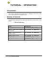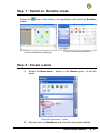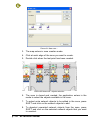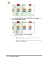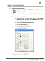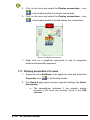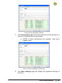
1
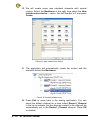
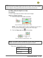
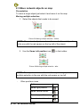
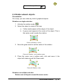
NLFACILITIES TUTORIAL
NEWRON SYSTEM
25-27 Boulevard Victor HUGO
31770 COLOMIERS (France)
T: +33 (0)5 61 15 18 45
F: +33 (0)5 61 15 16 44
Copyright NEWRON SYSTEM 2001-2007
Document version 0205001
p:2
NLFacilities manual
SUMMARY
Introduction................................................................................9
Benefit.......................................................................................10
New Management Tool generation ...............................................................10
Save time.......................................................................................................10
Professional integration .................................................................................10
Reliability .......................................................................................................10
Design reuse..................................................................................................11
What are LNS and the LNS databases? .......................................................11
Introduction .................................................................................................11
LNS.............................................................................................................11
LNS database .............................................................................................11
Architecture of the NLFacilities system .........................................................12
Installation of programs ..........................................................13
Configuration requirements ...........................................................................13
Installation......................................................................................................13
Installation of program ................................................................................13
Start with NLFacilities .............................................................16
Starting NLFacilities.......................................................................................16
NLFacilities terminology ................................................................................17
NLFacilities modes ........................................................................................18
Presentation................................................................................................18
Designer mode ...........................................................................................18
Runtime mode ............................................................................................18
NLFacilities views ..........................................................................................19
NLFacilities navigation...................................................................................21
Browsing through maps..............................................................................21
Navigating through maps............................................................................21
Scrolling of the graphical view ....................................................................23
Zooming features........................................................................................24
Objects selection ........................................................................................25
Selection of main modes of NLFacilities ....................................................25
Backup Restore NLFacilities project..............................................................26
Backup an NLFacilities project ...................................................................26
Restore an NLFacilities project...................................................................27
Requirements for creation of an NLFacilities project.....................................28
NLFacilities manual
p:3
Tutorial preview .......................................................................29
Tutorial files ...................................................................................................29
Modeler database for Tutorial........................................................................29
Objects........................................................................................................29
Zones..........................................................................................................30
IMPORTANT : Before starting .......................................................................33
Tutorial : Design ......................................................................36
Presentation...................................................................................................36
Backup of tutorials .........................................................................................36
Step 1 : Create a new project ........................................................................37
Step 2 : Network objects................................................................................43
2.1 Place device and network objects on map ...........................................43
2.2 Size network objects on map................................................................45
2.3 Move network objects on map..............................................................46
2.4 Rotate network objects .........................................................................47
Step 4 : Network objects appearances..........................................................49
Presentation................................................................................................49
Change appearance ...................................................................................50
Step 5 : Walls.................................................................................................51
Presentation................................................................................................51
Place walls..................................................................................................51
Step 5 : Network objects assignment ............................................................52
Presentation................................................................................................52
Place new objects.......................................................................................52
Step 6 : Install devices...................................................................................54
From the graphical view .............................................................................54
Macro installation........................................................................................54
Tutorial : operating ..................................................................56
Presentation...................................................................................................56
Backup of tutorials .........................................................................................56
Step 1 : Switch to Runtime mode ..................................................................57
Step 2 : Create a zone...................................................................................57
Step 3 : Apply zone updates on the network .................................................60
Step 4 : Switch profile of a network object.....................................................61
Step 5 : Modify a zone ...................................................................................63
5.1 : Show/Hide walls .................................................................................63
5.2 : Modify the shape of the zone .............................................................63
Step 6 : Objects feature .................................................................................66
6.1 Show names .........................................................................................66
Step 7 : Zones features .................................................................................67
7.1 : Display connections............................................................................67
7.2 : Display properties of a zone ...............................................................68
7.3 : Rename a zone ..................................................................................70
7.4 : Switch profile of a zone ......................................................................71
7.5 : Display master network objects of a zone..........................................71
p:4
NLFacilities manual
Tutorial : Advanced .................................................................73
Objects commands ........................................................................................73
Presentation................................................................................................73
Send on a single object ..............................................................................73
Send on a multiple objects .........................................................................74
Zone commands ............................................................................................75
Presentation................................................................................................75
Send command on Zone ............................................................................75
Host commands.............................................................................................76
Presentation................................................................................................76
Backup files of tutorial ................................................................................76
Step 1 : Create a host command................................................................77
Step 2 : Set host commands to zones........................................................79
Step 3 : Send host command on the network ............................................80
Schedulers.....................................................................................................80
Step 1 : Create the scheduler.....................................................................81
Step 2 : Define the scheduler .....................................................................82
Step 3 : Affect schedulers...........................................................................82
ANNEX ......................................................................................84
Details of NLFacilities views ..........................................................................84
Graphical View............................................................................................84
Object properties view ................................................................................85
Net points browser view .............................................................................86
Project hierarchy view ................................................................................87
Templates view...........................................................................................88
Object view .................................................................................................88
Host commands view .................................................................................89
Runtime navigation view.............................................................................89
Runtime Zoning view ..................................................................................90
Runtime Advanced view .............................................................................90
Boot page ...................................................................................................91
Objects browser view .................................................................................91
Output traces view......................................................................................92
Zoom map view ..........................................................................................93
Zones advanced ............................................................................................93
Check consistency of a zone......................................................................93
NLFacilities manual
p:5
PICTURES
Picture 1 NLFacilities system description ........................................................12
Picture 2 Install Step 1.....................................................................................14
Picture 3 Install Step 2.....................................................................................14
Picture 4 Install Step 3.....................................................................................14
Picture 5 Install Step 5.....................................................................................14
Picture 6 Install Step 6.....................................................................................14
Picture 7 NLFacilities Start menu ....................................................................16
Picture 8 General views of NLFacilities .........................................................19
Picture 9 Maps in Project hierarchy.................................................................21
Picture 10 Boot page sample ..........................................................................22
Picture 11 Scrolling in graphical view ..............................................................23
Picture 12 Before zoom ...................................................................................24
Picture 13 After zoom ......................................................................................24
Picture 14 Multiple selection of objects (1) ......................................................25
Picture 15 Backup NLFacilities project ............................................................26
Picture 16 Contents of NLFacilities backup file ...............................................27
Picture 17 Zone profile what we implemented ................................................31
Picture 18 Splitted type of connections ...........................................................32
Picture 19 Zone profile connections ................................................................33
Picture 20 NLFacilities Designer .....................................................................34
Picture 21 Restore contents for tutorial ...........................................................34
Picture 22 New project : general settings ........................................................37
Picture 23 New project : modeler database selection .....................................38
Picture 24 New project : selection of zone profile ...........................................38
Picture 25 New project : selection of objects profile ........................................39
Picture 26 New project : Map hierarchy...........................................................39
Picture 27 New project : New map ..................................................................40
Picture 28 New project : Map hierarchy...........................................................40
Picture 29 Supported features list ...................................................................41
Picture 30 SmartChannel ...............................................................................41
Picture 31 New infrastructure device...............................................................42
Picture 32 Created infrastructure.....................................................................42
Picture 33 Selection of default channel ...........................................................43
Picture 34 Select template...............................................................................44
Picture 35 device with objects .........................................................................44
Picture 36 Sizing on multiple selection : before...............................................45
p:6
NLFacilities manual
Picture 37 Sizing on multiple selection : after..................................................45
Picture 38 Moving multiple selection : before ..................................................46
Picture 39 Moving multiple selection : after .....................................................46
Picture 40 Rotation : before .............................................................................47
Picture 41 Rotation : move rotation center ......................................................47
Picture 42 Rotation : after ................................................................................47
Picture 43 Rotate multiple object : before........................................................48
Picture 44 Rotate multiple object : move center of rotation.............................48
Picture 45 Rotate multiple object : after...........................................................48
Picture 46 Same rotation for multiple object....................................................49
Picture 47 Same rotation for multiple object : object properties ......................49
Picture 48 Same rotation for multiple object : after .........................................49
Picture 49 Change appearance : before..........................................................50
Picture 50 Change appearance : select appearance ......................................50
Picture 51 Change appearance : after.............................................................50
Picture 52 Place walls......................................................................................51
Picture 53 Objects panel of Designer bar........................................................52
Picture 54 New unassigned object ..................................................................53
Picture 55 Select device for assignment .........................................................53
Picture 56 Select unassigned object for assignment.......................................53
Picture 57 Install device...................................................................................54
Picture 58 NLFacilities Designer .....................................................................57
Picture 59 NLFacilities Runtime ......................................................................57
Picture 60 “New zone...” option .......................................................................57
Picture 61 New zone… ....................................................................................58
Picture 62 New zone : objects selection..........................................................58
Picture 63 New zone : graphical settings ........................................................59
Picture 64 Send updates .................................................................................59
Picture 65 Apply updates.................................................................................60
Picture 66 Switch profile : before.....................................................................61
Picture 67 Switch profile : selection of new profile ..........................................62
Picture 68 Modify zone : change zone shape (1) ............................................64
Picture 69 Modify zone : change zone shape (2) ............................................64
Picture 70 Modify zone : objects selection ......................................................65
Picture 71 Objects names................................................................................66
Picture 72 Graphical settings...........................................................................67
Picture 73 Display connections .......................................................................68
Picture 74 Zone properties : General ..............................................................69
Picture 75 Zone properties : Connections .......................................................69
Picture 76 Zone properties : Zone settings......................................................70
Picture 77 Rename zone .................................................................................70
Picture 78 Display masters ..............................................................................72
Picture 79 Object commands ..........................................................................73
Picture 80 Objects commands.........................................................................74
Picture 81 Zone commands.............................................................................75
Picture 82 Host commands..............................................................................76
NLFacilities manual
p:7
Picture 83 Create host command ....................................................................77
Picture 84 Create host command filled............................................................78
Picture 85 Host commands options group.......................................................79
Picture 86 Configure host command ...............................................................79
Picture 87 Set host commands to zones : apply updates ...............................80
Picture 88 Send host command ......................................................................80
Picture 89 Graphical view ................................................................................84
Picture 90 Object properties view....................................................................85
Picture 91 Browser view ..................................................................................87
Picture 92 Project hierarchy view ....................................................................87
Picture 93 Templates view...............................................................................88
Picture 94 Objects view ...................................................................................89
Picture 95 Host commands view .....................................................................89
Picture 96 Runtime navigation view ................................................................90
Picture 97 Runtime zoning view ......................................................................90
Picture 98 Runtime advanced view .................................................................91
Picture 99 Boot page sample ..........................................................................91
Picture 100 Output trace view .........................................................................92
Picture 101 Zoom view ....................................................................................93
Picture 102 Check zone consistencies............................................................94
p:8
NLFacilities manual
INTRODUCTION
Thank you for choosing NLFacilities software.
We are happy to help you in your LonWorks integration job. Do not
forget to check the latest version through our web site.
NLFacilities manual
p:9
BENEFIT
New Management Tool generation
NLFacilities is a LNS manager tool that allows integrators to develop
graphical applications for the management and layout of living space.
This program complements a supervision and is aimed at the same
clients : integrators and end customers. It provides object monitoring.
Save time
NLFacilities belongs to a major software suite broadly used all over
Europe and aimed to decrease integration time. The first idea is to
apply template stored in a database instead of manually linking the
devices. The second point is to prevent from reinventing the wheel by
generating the SCADA while integrating the network.
Professional integration
NLFacilities separates jobs depending on skills. A trained technician is
no more mandatory at all integration phases. He only designs
integration and every technician without any LonWorks know-how can
integrate. NLFacilities is fully graphic and intuitive: it includes no
technological word.
Reliability
NLFacilities dramatically improves reliability. The zone template
mechanism force a pre-design of the integration and anticipate future
problems. It also prevents from making any mistake and missing. The
graphical representation of the zones allows an easy and intuitive
understanding of the links even two year later. Evolution maintenance is
also very easy : you update the zone template and apply it recursively
on the global project.
p : 10
NLFacilities manual
Design reuse
The zone templates are stored in reusable database. This collection of
databases define your system solution. The more you integrate, the
more solution you can propose, the less job need to be done.
What are LNS and the LNS databases?
Introduction
NLFacilities is based on the LNS engine and fully use its functionality
to configure your network.
LNS
LNS is a software engine that provides a standard interface between a
computer and the LonWorks networks.
This LNS engine gives the ability to a Windows program to perform
networking function on LonWorks networks, like :
-
Installation of devices
-
Management of devices (Repair, Download, …)
-
Configuration of devices
-
Monitoring of devices
-
…
LNS gives the ability to work on the same LonWorks network through
several applications at a time. And also to access a network through a
remote connection between computers.
LNS database
An LNS database represents a LonWorks network.
This LNS database filled by LNS through any kind of LNS manager tool
(like NL220), when you will add, for instance, new devices in your
network.
NLFacilities manual
p : 11
Architecture of the NLFacilities system
1
b
a
NLModeler
Dedicated
c
Template
Database
2
d
Network 1
NLFacilities
e
LNS Databases
NLFacilities
Database
Picture 1 NLFacilities system description
1 – NLModeler is used to create the templates
a) The template database is generated by NLModeler.
b) You always have a dedicated LNS database for the template
database
2 – NLFacilities is used to manage the site
c) NLFacilities uses the template database to translate the content of
the LNS databases
d) Using NLFacilities will automatically fill the NLFacilities database
that will represent your site.
e) Creating zones will automatically fill the LNS database to update
your network.
p : 12
NLFacilities manual
INSTALLATION OF PROGRAMS
This section explains how to install the NLFacilities program
Configuration requirements
The table below shows the minimum configuration and the
recommended configuration for the installation and correct functioning
of the program.
Equipment
Operating system
Computer
Memory
Hard disk
CD ROM
Software
Interface network
Minimum
Windows NT, 2000, Xp
Pentium III 350 Mhz,
800 x 600 screen
64 M octets
100 Mo
- 50 Mo for program
- 0,5 to 8 Mo per
project
Required
for
installation
- LNS 3.0 or greater
Type NSI or VNI card
Recommended
Windows NT, 2000, Xp
Pentium III 750 Mhz,
1024 x 768 screen
128 M octets
200 M octets
Required
for
installation
- LNS 3.0 or greater
Type NSI or VNI card
Table 1 The equipment
Installation
A setup program will guide you through the installation procedure and
will ask you for any information necessary.
Installation of program
1. Insert the CDROM in the CD reader
2. If no window appears on the screen open: D:\MaquetteCD01.exe
3. Startup page of the setup CD will appear on the screen.
4. Select NLSuite on main Menu
5. The NLSuite icon list will appear on the screen.
6. Select
on left of screen.
NLFacilities manual
p : 13
7. NLFacilities installation page will appear on the screen.
8. Click on Install button, to start the NLFacilities setup program.
Picture 2 Install Step 1
Picture 3 Install Step 2
Picture 4 Install Step 3
The NLFacilities setup program will now be ready and the progress of
setup program will appear on the screen. Follow the instructions until
you arrive at type of installation choice.
Picture 5 Install Step 5
p : 14
NLFacilities manual
Picture 6 Install Step 6
You have the choice between the following installations:
Installation
Complete
Custom
Details
Complete
installation
of
NLFacilities
NLModeler.
You can choose the module to be installed
and
Table 2 Type of installation
You should restart your PC at the end of the installation, according to
the instructions.
NLFacilities manual
p : 15
START WITH NLFACILITIES
Starting NLFacilities
To Start NLFacilities, go to the NLFacilities - visual office designer
folder from the Start menu of windows.
Picture 7 NLFacilities Start menu
Then you are able to start NLFacilities in runtime or design mode.
To start in Runtime mode click on NLFacilities – Runtime.
To start in Designer mode click on NLFacilities – Designer.
p : 16
NLFacilities manual
NLFacilities terminology
Name
Description
Project
Main NLFacilities database.
It manages one or several LNS databases with maps that
represent graphically the site.
Map
Full or partial graphical view of a site.
A map contains network objects and zones.
This can be any kind of site representation.
Network objects
Graphical NLFacilities objects that represent devices present on
the network of the site.
This can be Controllers, actuators, sensors, lights, buttons,
blinds,… or any kinds of objects that can be represented by a
LonWorks device.
Zones
Graphical zones drawn in NLFACILITIES Designer or Runtime.
A zone will create relations between network objects that belong
to the zone and will configure the network objects to put them in
the correct state to work in the zone.
NLFacilities manual
p : 17
NLFacilities modes
Presentation
NLFacilities gives access to different modes that are provided to
perform different sets of operations on the LonWorks network and the
graphical views.
The modes are splitted in main modes that are :
-
Designer mode
-
Runtime mode
Designer mode
The Designer mode provides functionality to create the LNS database
that corresponds to a site and create the graphics that represents the
site.
Three usages are possible :
-
define the graphics of the site by positioning geographically the
network objects on the different maps.
-
define the LNS database content of the site, according to your
LonWorks network topology, or perform maintenance functions on
the network.
-
link and configure network objects by creating and managing
zones.
Runtime mode
The Runtime mode is the mode that allows to manage the site that has
been previously defined in Designer mode.
In Runtime mode you will be able to :
-
Link and configure network objects by creating and managing
zones
-
Perform maintenance functions to check the health of the network
-
Perform lite graphical representation of the network values of the
network objects
NOTE: It is possible to switch at any time from a mode to another to
perform the different actions available in NLFacilities.
p : 18
NLFacilities manual
NLFacilities views
NLFacilities uses docking windows to display project’s content.
NLFacilities is a strongly contextual-mouse-featured oriented
application.
8
7
5
1
2,3,4
6
Picture 8 General views of NLFacilities
1 Graphical view
Allow map-based graphical edition.
2 Object properties
Displays properties related to any object selected from other windows.
3 Net points browser
Displays values of net points to be observed.
A second browser window is also available from the menus.
4 Objects browser
Displays different hierarchies of objects in map and LNS database.
5 Zoom map
Displays a snapshot of the whole map to allow quick positioning in the
main map window.
6 Output traces
Execution messages and alerts are listed to this window.
7 Designer bar
Main view of the Designer mode that contains several panels:
-
Project hierarchy
NLFacilities manual
p : 19
-
Device template manager
-
Object profiles manager
-
Host commands manager
8 Toolbars and menus
Give access to any function.
p : 20
NLFacilities manual
NLFacilities navigation
Browsing through maps
See the list of maps
The maps are listed in the Project hierarchy view.
Picture 9 Maps in Project hierarchy
Open a map in the graphical view
To Open a map:
-
Double click on the map you want to open in the Project
Hierarchy view.
OR
-
Right click and select the Display option in the contextual menu of
the map.
Navigating through maps
Presentation
The application offers a pure graphical way to navigate through different
maps: the boot page and graphical shortcuts.
Boot page is automatically produced at project creation.
NLFacilities manual
p : 21
Picture 10 Boot page sample
Customize a boot page
You need first to give the map background. Then you draw shortcuts on
the map that lead directly to other maps.
To draw a shortcut be sure to be in designer mode and choose the
menu option “Graphic tools”/ “draw shortcuts to other map”.
You then draw the frame of the shortcut and then edit the object
properties to select the target map but also the hot track appearance
.
p : 22
NLFacilities manual
Scrolling of the graphical view
Presentation
When a map is displayed in the Graphical view, NLFacilities gives the
ability to scroll on the map.
Scroll with zoom view
1. Right click on the zoom rectangle present in the Zoom view
2. Scroll the rectangle inside the Zoom view it will automatically
scroll the graphical view.
Picture 11 Scrolling in graphical view
Scroll directly from the graphical view
1. Press CTRL + Right click on the graphical view.
Result : A Hand cursor appears on the screen.
2. Scroll the hand inside the graphical view it will automatically
scroll the graphical view.
NLFacilities manual
p : 23
Zooming features
Presentation
When a map is displayed in the Graphical view NLFacilities gives the
ability to zoom in/zoom out on the map to ease work.
Zoom from the Zoom view
1. Left click over the Zoom view.
Result : A cross cursor appears
2. Draw the zoom rectangle needed
3. Release the Mouse button,
Result : The graphical view is automatically zoomed on the
rectangle drawn.
Picture 13 After zoom
Picture 12 Before zoom
Zoom directly from the graphical view
1. Click on the graphical view
2. Press CTRL + Move the Mouse wheel.
Result : The graphical view is automatically zoom in or out.
CTRL+
CTRL+ALT+
p : 24
NLFacilities manual
Low zooming
Fast zooming
Objects selection
Select objects
1. In the graphical view, draw a rectangle selection to select the
objects.
2. Press SHIFT and selects other objects in the view to add them
to the selected objects.
Picture 14 Multiple selection of objects (1)
NOTE : When there is a multiple selection the reference network object
is marked with a red square on the upper left corner of the object.
Deselect objects
1. Press SHIFT and click on the network objects you want to
deselect.
OR
2. Click on empty part of map to clear whole selection
Selection of main modes of NLFacilities
Switch from Runtime to Designer
If the application is running in Runtime mode pressing the
switch the application in Designer mode.
icon will
If the application is running in Designer mode pressing the
switch the application in Runtime mode.
icon will
NLFacilities manual
p : 25
Backup Restore NLFacilities project
Backup an NLFacilities project
1. All project must be closed.
2. Select the Backup… option in the Project menu.
Picture 15 Backup NLFacilities project
3. Select in the Existing projects list the project you want to backup
4. Check the elements you want to backup in the Elements to
backup list.
5. Select the backup file to create in the Dest. Backup file.
6. Press Backup to launch the backup process.
NOTE : only Local LNS databases can be included to the backup file.
Remote databases will never be included in the project.
p : 26
NLFacilities manual
Restore an NLFacilities project
1. All project must be closed.
2. Select the Restore… option in the Project menu.
3. Select the backup file you want to restore.
4. Click Next>> to extract the content of the backup file.
5. The content of the backup file is displayed.
6. Check the elements you want to restore by checking the :
Restore NLFacilities project, Restore modeler database and
Restore LNS databases checkboxes.
Picture 16 Contents of NLFacilities backup file
7. Click on Next>> to restore the selected elements.
NLFacilities manual
p : 27
Requirements for creation of an NLFacilities
project
To create a new NLFacilities project you need:
p : 28
-
A Modeler database that suits your site needs
-
The Modeler LNS database.
-
Images that represents your site. It is highly recommended
to use WMF files to get gain of vectorial display system.
-
LNS databases created with NLFacilities Designer or
NL220 that contain the architecture of the site.
NLFacilities manual
TUTORIAL PREVIEW
Tutorial files
All the files needed for the Tutorial are located in :
C:\Program Files\Newron System\NLFacilities\Tutorial
The files provided for the tutorial are:
-
Map.wmf : image that represents the tutorial floor.
-
ModelerDatabase.gz : backup of the complete modeler
database that will be used fro the NLFacilities project.
-
NLBlind.xif: XIF file of a device template to import in the
LNS database.
Modeler database for Tutorial
Objects
Network
Object type
Default icon
Description
RemoteControl
Network objects that represent an
InfraRed
controller
on
the
network.
Light
Network objects that represent
Lights units on the network.
FanCoil
Network objects that represent
FanCoil units on the network.
NLFacilities manual
p : 29
Network objects that represent
Blinds units on the network.
Blind
Profile of objects
Presentation
A network object always has an associated profile or Object profile.
An object profile is a law of configuration that is used by NLFacilities to
identify how to configure and to link a network object when it is put in a
zone.
List of available profiles for each network object
Network object
Available object profile
type
st
RemoteControl
RemoteControl prf 1 : 1 type of object profile
available for network objects RemoteControl.
st
Light
Light prf 1 : 1 type of object profile available for
network objects Light.
nd
Light prf 2 : 2 type of object profile available for
network objects Light.
st
FanCoil
FanCoil prf 1 : 1 type of object profile available for
network objects FanCoil.
st
Blind
Blind prf 1 : 1 type of object profile available for
network objects Blind.
nd
Blind prf 2 : 2 type of object profile available for
network objects Blind.
Zones
Presentation
The modeler database contains profile of zones.
A profile of zone consists of a set of laws that will be used by
NLFacilities to link and configure network objects that will be affected
in a zone.
p : 30
NLFacilities manual
Description of profile « Zone »
The picture below indicate what we have configure in the Modeler
database of the tutorial :
Picture 17 Zone profile what we implemented
-
Remote control has 2 lights button, each one command a set of
lights.
-
Remote control has Blinds buttons that will command the
direction of blinds.
-
Remote control has FanCoil speed buttons that will command
the speed of the FanCoils.
We can see that this zone profile result of several rules of connections
represented below.
NLFacilities manual
p : 31
Picture 18 Splitted type of connections
At this step you see that you have 2 rules that can be applied to lights.
The selection of the rule that must be applied to a light will be done in
NLFacilities by chosing the profile of the light.
As a consequence you will finally obtain the links as shown below.
p : 32
NLFacilities manual
Picture 19 Zone profile connections
IMPORTANT : Before starting
Before starting the Tutorial of NLFacilities, you need to Restore the
Modeler database and LNS database that will be used for the rest of the
tutorial.
1. Open NLFacilities in Designer mode.
NLFacilities manual
p : 33
Picture 20 NLFacilities Designer
2. Select the option Restore… in the Project menu.
3. Explore the disk and select the C:\Program Files\Newron
System\NLFacilities\Tutorial\ModelerDatabase.gz file
4. Click on Next>>
5. See that the restore process proposes to make the restore of :
•
Modeler database called : NLTutorial
•
LNS database called : DEMO
Picture 21 Restore contents for tutorial
p : 34
NLFacilities manual
6. Check the Restore modeler database checkbox and Restore
LNS database checkbox to restore both the modeller
database and LNS database.
7. Press Next>> to launch the restore process.
NLFacilities manual
p : 35
TUTORIAL : DESIGN
Presentation
The Tutorial Design how to initialize an NLFacilities project and how to
place objects on maps.
Backup of tutorials
You will find a backup file for each step describe in the tutorial in the
folder :
-
C:\NLFacPrj\Backups
Step
File
Step 1 : Create a new project
NLTUTORIAL_DESIGN_step01.gz
Step 2 : Network objects
NLTUTORIAL_DESIGN_step02.gz
Step 3 : Network objects appearances
NLTUTORIAL_DESIGN_step03.gz
Step 4 : Walls
NLTUTORIAL_DESIGN_step04.gz
Step 5 : Network objects assignment
NLTUTORIAL_DESIGN_step05.gz
Step 6 : Install devices
NLTUTORIAL_DESIGN_step06.gz
p : 36
NLFacilities manual
Step 1 : Create a new project
1. Select the option New… in the Project menu.
Picture 22 New project : general settings
2. Enter NLTutorial as name for the new project.
3. Leave default settings
a. Leave the default path gave by NLFacilities as location
of storage for the project.
b. Leave the Mono network database settings. It means
that the project will work only on a single network
database.
4. Click Next>>
5. NLFacilities asks for the Modeler database that will be used to
create the project. Select the NLTutorial modeler database that
is present in the list of modeler database found.
a. If no modeler database are found, click on Browse…,
explore through the disk to the C:\NLModeler
Dbs\NLTutorial folder and select the Modeler.ndb file.
NLFacilities manual
p : 37
Picture 23 New project : modeler database selection
6. Click Next>>
7. NLFacilities asks for the selection of zone profiles that will be
available in the project. Check the Corridor and Zone profiles
Picture 24 New project : selection of zone profile
8. Click Next>>
9. NLFacilities asks for the profile of objects that will be available
in the project. Check all the available profiles in the list.
p : 38
NLFacilities manual
Picture 25 New project : selection of objects profile
10. Click on Next>> to define maps
Picture 26 New project : Map hierarchy
11. Click on New map... to create a map in the project
NLFacilities manual
p : 39
Picture 27 New project : New map
12. Give Map#1 as name for the new map.
13. Click on the “…” button to explore the disk to select the correct
background image to use for the new map.
14. Go in the C:\Program Files\Newron System\NLFacilities\
Tutorial folder and select the Map.wmf file.
15. Click on OK to create the map
Picture 28 New project : Map hierarchy
16. Click on Next>>
p : 40
NLFacilities manual
17. The project is created
18. A dialog is displayed to indicate that the XIF files used by the
modeler database will be automatically imported in the LNS
database. Leave the dialog as it is and press OK to continue.
The device templates are automatically created in the LNS
database
Picture 29 Supported features list
19. The application then launches the infrastructure tool called
SmartChannel that will help you to easily define the
infrastructure of the LNS database. See that the Backbone
channel is present in the list of available channels in the LNS
database.
a. On the left view of SmartChannel you see the list of
available LNS database.
b. On the right view of SmartChannel you see the
Infrastructure of the LNS database
Picture 30 SmartChannel
NLFacilities manual
p : 41
20. We will create some new standard channels with normal
routers. Select the Backbone in the right view select the New
infrastructure device… option. Set the Number to 3 and press
Create.
Picture 31 New infrastructure device
21. The application will automatically create the routers and the
channels behind the Backbone.
Picture 32 Created infrastructure
22. Press Exit to come back in the zoning application. You can
select the default channel for a map: select Router1_Channel
in the list to indicate that the devices created in the map will be
automatically put in the Router1_Channel channel. Press OK
to validate
p : 42
NLFacilities manual
Picture 33 Selection of default channel
23. The map is now opened created and fully ready to be used.
Devices set on the map will be located in the corresponding
channel. You can of course change manually channels per
device.
Step 2 : Network objects
2.1 Place device and network objects on map
1. Select in the list of available device templates the Device
template NLBlind.
NLFacilities manual
p : 43
Picture 34 Select template
2. Move the Mouse over the graphical map. The mouse pointer is
now the device image. Move over the placement you want to
create the device and just left click at the placement.
3. A dialog is opened to ask how many objects you want to put
next to the device that will be create. Set number of Blind prf 1
to 3 and select the Place objects around the device option.
Press Continue. The device is created with 3 objects
around it.
Picture 35 device with objects
4. Do the same operation several times to drop all the objects
available in NLBlind, NLLightFanCoil, NLSensor on the map.
p : 44
NLFacilities manual
NOTE : The first time a type of object is dropped on the view the size is 32*32.
In this case size the network object to the size you want. Then, other dropped
network objects of this type will have the size you have previously set.
2.2 Size network objects on map
Presentation
To size a single object just select it and move its edges.
Sizing on multiple selection
1. Select the objects that needs to be sized.
Picture 36 Sizing on multiple selection : before
NOTE : The network objects used as reference for the size is
the one with the red square on the top left of the object.
2. Click the Same size icon (
) in the toolbar.
Picture 37 Sizing on multiple selection : after
NOTE: The object uses as reference for any sizing operation on
multiple selection is the one with the red square on top left.
-
Other same sizing position icons
Action
Icon
Same height
Same width
NLFacilities manual
p : 45
2.3 Move network objects on map
Presentation
To move a single object just select it and move it on the map.
Moving multiple selection
1. Select the objects that needs to be moved.
Picture 38 Moving multiple selection : before
NOTE : The network objects used as reference for the set of position
is the one with the red square on the top left of the object.
2. Use the Same Left position icon (
) in the toolbar.
Picture 39 Moving multiple selection : after
NOTE: The object uses as reference for any moving operation on
multiple selection is the one with the red square on top left.
-
Other positions icons
Action
Same right position
Same vertical center
Same top position
Same horizontal center
p : 46
NLFacilities manual
Icon
Same bottom position
2.4 Rotate network objects
Presentation
On a map, you can rotate any kind of graphical objects.
Rotation on single selection
1. Activate the rotation mode (
)
2. Select the object to rotate in the view:
a. Yellow marks appear at the edges of the object.
b. A green mark appear at the center of the object. This is
the center used to make the rotation.
Picture 40 Rotation : before
3. Move the green mark to set the center of the rotation.
Picture 41 Rotation : move rotation center
4. Place the cursor over a yellow mark, click and move it, the
object will rotate around the Green mark.
Picture 42 Rotation : after
Rotation on multiple selection
Rotate a set of objects around the same center
NLFacilities manual
p : 47
1. Activate the rotation mode (
)
2. Select the objects to rotate in the view:
a. Yellow marks appear at the edges of the objects.
b. A green mark appear at the center of the objects.This is
the center used to make the rotation.
Picture 43 Rotate multiple object : before
3. Move the green mark to set the center of the rotation.
Picture 44 Rotate multiple object : move center of rotation
4. Place the cursor over a yellow mark, click and move it, the
objects will rotate around the Green mark.
Picture 45 Rotate multiple object : after
Set the same rotation for a selection of objects
1. Select all the objects that needs to be rotated.
p : 48
NLFacilities manual
Picture 46 Same rotation for multiple object
2. In the Object properties view, enter in the Orientation line the
orientation you want in degrees.
Picture 47 Same rotation for multiple object : object properties
3. Select another line of the Object properties view to validate
the orientation.
Picture 48 Same rotation for multiple object : after
Step 4 : Network objects appearances
Presentation
An object can have several appearances. The appearances does not
change the way of running of a network object in a zone as opposite to
the object profile.
NLFacilities manual
p : 49
Change appearance
1. Select the VOBJBlind1 object in the graphical view.
Picture 49 Change appearance : before
2. Right click and select the Change appearance option in the
contextual menu.
Picture 50 Change appearance : select appearance
3. Select the new appearance in the window.
4. Press Enter to validate the new appearance.
Picture 51 Change appearance : after
p : 50
NLFacilities manual
NOTE : You can also change the appearance of a set of objects. Just
select the objects you want to change. And select the Change
appearance… option in the contextual menu.
Step 5 : Walls
Presentation
Walls can be put on maps to Show/Hide certain part of a image
background.
For instance, this can be used to Show/Hide spans that are drawn on
the background.
Place walls
1. On tools toolbar, click on the
mode in drawing wall on map.
icon to change the edition
2. Place the wall directly other the drawn walls the map.
Picture 52 Place walls
NOTE: A wall is considered as any graphical objects available on a
map. As a consequence, you can use the size, move, rotate features
explained previously for the Network objects to place the walls.
NLFacilities manual
p : 51
Step 5 : Network objects assignment
Presentation
We saw a way to place network objects on the map by creating the
device (see Step 3)
Now we will see another way to create network objects in adding a new
network object and then link them to a device.
Place new objects
1. Select the “Objects” panel of the Designer bar
Picture 53 Objects panel of Designer bar
2. Double click on the Blind prf 1 item in the list. It will open the
Appearance dialog. Select the appearance you want to use.
3. Move the mouse over the graphical view and left click where
you want to create the object. An object is created on the map
with a question mark on the top left. The question mark
indicates that the object is unassigned and not linked to any
device for the moment.
p : 52
NLFacilities manual
Picture 54 New unassigned object
4. Select the Assignation mode tool in the toolbars to start the
assignation mode and be able to link the unassigned object to a
device.
5. Move the mouse over the graphical view and select first the
device to which the unassigned object will be linked.
Picture 55 Select device for assignment
6. Then select the unassigned object to link
Picture 56 Select unassigned object for assignment
7. The question mark disappear and the object is now linked to the
device.
8. Press Escape to quit the Assignation mode
NOTE: You can assign several objects one after the other using this
method.
If you want to change the output number of the assigned object, just
right click on it and select the Change output number… option in the
menu.
NLFacilities manual
p : 53
Step 6 : Install devices
From the graphical view
1. Before being able to install a device on the Network. Be sure
that the Attach to network icon (
) is checked. (This can be
done only if a Network interface has been used to open the
LNS database).
2. Right click on the device you want to install in the graphical
view. Select the Install… option in the menu.
3. Enter manually the NeuronID of the device to install OR Press
Service button of the device to install.
Picture 57 Install device
NOTE: You can select several devices, the Install… command will then
ask NeuronID for each selected device.
Macro installation
Presentation
The application allows you to install several devices one after the other.
You can for instance Install… all the devices of a subsystem or channel.
Installation on devices of a subsystem
1. Select the Objects view and in the Objects view select the
Network page. You will see the complete hierarchy of the LNS
database of the map sorted by subsystems.
2. Right click on the Map#1 subsystem. Select the option
Nodes\Network\Install/Replace\Install uninstalled devices
p : 54
NLFacilities manual
3. This command will explore each device present in the
subsystem and ask for each device its NeuronID.
NOTE: By checking/unchecking the option Nodes/Recursive
commands on subsystem you will indicate if the command is
launched only on the selected subsystem or also on its children.
NOTE Bis: From the subsystem menu you can notice that many
functions are available as macro functions, like Test, Reset, Repair,…
NLFacilities manual
p : 55
TUTORIAL : OPERATING
Presentation
The tutorial operating will explain how to manage a site once it has
been totally designed in Designer mode.
Backup of tutorials
You will find a backup file for each step describe in the tutorial in the
folder :
-
C:\NLFacPrj\Backups
Steps
Backup files
Step 1 : Create a zone
NLTUTORIAL_OP_step01.gz
Step 2 : Apply zone updates on NLTUTORIAL_OP_step02.gz
the network
p : 56
Step 3 : Switch profile of a
network object
NLTUTORIAL_OP_step03.gz
Step 4 : Modify a zone
NLTUTORIAL_OP_step04.gz
Step 5 : Objects feature
NLTUTORIAL_OP_step05.gz
Step 6 : Zones features
NLTUTORIAL_OP_step06.gz
NLFacilities manual
Step 1 : Switch to Runtime mode
Select the
mode.
icon in the toolbar, the application will switch in Runtime
Picture 58 NLFacilities Designer
Picture 59 NLFacilities Runtime
Step 2 : Create a zone
1. Select the New zone… option in the Zones group of the left
panel
Picture 60 “New zone...” option
2. Set the name to NewZone and leave the description blank.
NLFacilities manual
p : 57
Picture 61 New zone…
3. The map enters in zone creation mode.
4. Click at each edge of the zone you want to create.
5. Double click when the last point has been created.
Picture 62 New zone : objects selection
6. The zone is closed and created, the application enters in the
mode to select the objects available in the zone.
7. To select extra network objects to be added in the zone, press
SHIFT and click on the network objects to add.
8. To deselect unwanted network objects from the zone, press
SHIFT and click on the selected network objects that you want
to unselect.
p : 58
NLFacilities manual
9. To finalize the selection of the network objects of the zone,
press ENTER.
10. The zone graphical properties dialog is displayed.
Picture 63 New zone : graphical settings
11. Press Enter to finalize the zone.
12. The updates are automatically sent to the network, the bindings
and configuration properties are set by the application.
Picture 64 Send updates
NLFacilities manual
p : 59
Step 3 : Apply zone updates on the network
When network updates are available on a map. The Apply updates on
network icon (
)is flashing.
Press the Apply updates on network icon (
Picture 65 Apply updates
p : 60
NLFacilities manual
) to send the updates.
Step 4 : Switch profile of a network object
Presentation
Switching the profile of a network object will change the way it will be
bound or configured when it will be inserted in a zone.
See the presentation of the Modeler objects for more explanation on the
available profiles of objects.
For example, changing the profile of the network object Light 1 from
Light prf 1 to Light prf 2, will imply that the connections of the zone
NewZone previously created will pass from zone connection 1 to zone
connection 2 (See below)
Zone connection 1
Zone connection 2
Switch profile of object Light 3
1. Select the object Light 3 in the graphical view.
Picture 66 Switch profile : before
2. Select the Switch object profile icon (
toolbar.
) in the floating
3. Select the profile Light prf 2 in the drop down list of available
profiles for the network object.
NLFacilities manual
p : 61
Picture 67 Switch profile : selection of new profile
4. The profile of the object is changed and the zone to what it
belongs, is marked as updated.
5. The updates are sent and the connections are the one shown
as Zone connection 2
p : 62
NLFacilities manual
Step 5 : Modify a zone
5.1 : Show/Hide walls
1. Press the Show/Hide walls icon (
walls mode.
) to activate the Runtime
2. The walls that can be shown or hidden appears with a blue
frame.
3. Click on the wall on the center of the zone, to activate it.
4. Press the Escape button to quit the Runtime walls
5. The center wall is now visible on the map.
5.2 : Modify the shape of the zone
1. Select the zone NewZone on the map.
2. Select the Modify icon (
) in the floating toolbar.
a. Yellow marks appears at the edges of the zone.
b. When the cursor is over the frame of the office you can
act 2 ways.
Cursor
Description
Add a new point for edges of the
zone.
Move an existing edge of the zone.
3. Click on the top left yellow mark of the zone and drag it at the
previous shown wall level.
NLFacilities manual
p : 63
Picture 68 Modify zone : change zone shape (1)
4. Click on the bottom left yellow mark of the zone and drag it at
the previous shown wall level.
Picture 69 Modify zone : change zone shape (2)
5. Press Enter to validate the new shape of the zone.
a. The application then enters in the mode for selection of
the network objects of the zone.
b. The network objects that are no more over the zone are
automatically deselected.
p : 64
NLFacilities manual
Picture 70 Modify zone : objects selection
6. Leave the new selection as it is.
7. Press Enter to validate the modification of the zone.
8. The updates are automatically sent to the network
NLFacilities manual
p : 65
Step 6 : Objects feature
6.1 Show names
1. Press the Show names icon (
) to display names of the
network objects directly on the map.
2. To modify the size of the font used for the network objects
names :
a. Right click on the NLTutorial item in the Project
hierarchy view, select the Properties option in the
contextual menu.
b. Select the Graphical settings page.
c.
Set the Objects font size to 2 and press Enter.
Picture 71 Objects names
p : 66
NLFacilities manual
Step 7 : Zones features
7.1 : Display connections
1. Click on the zone and select the Display connections… icon
(
) in the floating toolbar.
2. The connections of the zone are graphically displayed on the
map.
3. To change the depth of the lines :
a. Right click on the NLTutorial item in the Project
hierarchy view and select the Properties option from
the contextual menu.
b. Select the Graphical settings page.
c.
Set the Links width to 5.
d. Set the Links end width to 10.
e. Press OK to validate
Picture 72 Graphical settings
4. Right click on the zone NewZone.
NLFacilities manual
p : 67
5. Click on the zone and select the Display connections… icon
(
) in the floating toolbar to hide the connections.
6. Click on the zone and select the Display connections… icon
(
) in the floating toolbar to finally display the connections.
Picture 73 Display connections
7. Right click on a graphical connection to see its properties
window automatically appeared.
7.2 : Display properties of a zone
1. Select the zone NewZone in the graphical view and select the
Properties icon (
) in the floating toolbar.
2. The General page gives access to general settings like Name,
Description,…
a. The spreadsheet indicates if the network objects
member of the zone are correctly found in the LNS
database.
p : 68
NLFacilities manual
Picture 74 Zone properties : General
3. The Connections page list all the connections that should be in
the zone, and gives their current state.
a. NOTE: If extra connections are present, they won’t
appear there.
Picture 75 Zone properties : Connections
4. The Zone settings page will display the graphical settings of
the zone.
NLFacilities manual
p : 69
Picture 76 Zone properties : Zone settings
7.3 : Rename a zone
1. Select the zone NewZone in the graphical view and select the
Properties icon (
) in the floating toolbar.
2. Enter NewName
Picture 77 Rename zone
3. Press Enter to validate the change of the zone name.
p : 70
NLFacilities manual
7.4 : Switch profile of a zone
Presentation
NLFacilities allows to change the profile of a zone from one to another.
The profile of zones available for switch are automatically processed
from the type of objects that are available in the zone.
Switch the profile of a zone
1. Select the zone NewName in the graphical view and select the
Switch profile icon (
) in the floating toolbar.
2. Select in the Zone profile list the profile that must be applied to
the zone.
a. NOTE:In the Tutorial only one profile of zone is
available).
7.5 : Display master network objects of a zone
1. Select the zone NewName in the graphical view and select the
Display masters icon (
) in the floating toolbar.
2. The term Master appears above each Master of the zone.
3. To change the font size:
b. Right click on the NLTutorial item in the Project
hierarchy view. Select the Properties option in the
contextual menu.
c.
Select the Graphical settings page.
d. Set the Masters font size to 2.
e. Press Enter.
NLFacilities manual
p : 71
Picture 78 Display masters
p : 72
NLFacilities manual
TUTORIAL : ADVANCED
Objects commands
Presentation
In NLModeler you have the possibility to define commands that can be
launched on a network object(s).
An object command is a set of value that will be written on the network
on the network variable or configuration properties of a network object.
Commands can be configured to be accessed from Commands
window or directly from a second floating toolbar.
Send on a single object
1. Select the VOBJBlind2 object in the map. Double click on it or
select the Commands… icon (
) in the floating toolbar.
a. The list of available commands on the object are
displayed.
Picture 79 Object commands
2. Click on the command Blind UP to send the command on the
network.
3. The right part of the view contain an object browser. Select the
object you want to browse in the Selected object list, you will
then see the detail of the object.
NLFacilities manual
p : 73
NOTE : If the modeler is designed for, it is possible that the command
icon is directly accessible from a second floating toolbar.
Send on a multiple objects
1. Select all the objects in the map.
2. Select the Commands… icon (
) in the floating toolbar.
3. The list of all available commands on the selected objects are
displayed.
4. Click on the command Blind UP to send the command on the
network.
a. The command will be sent only on the objects to which
the command Blind UP can be sent. That is to say,
VOBJBlind1, VOBJBlind2, VOBJBlindX
Picture 80 Objects commands
p : 74
NLFacilities manual
Zone commands
Presentation
In NLModeler you have the possibility to define commands that can be
launched on a zone.
A zone command is a set of value that will be written on the different
objects available in the zone.
Commands can be configured to be accessed from Commands
window or directly from a second floating toolbar.
Send command on Zone
1. Select the NewName zone in the map. Double click on it or
select the Commands… icon (
) in the floating toolbar.
2. The list of available commands on the object are displayed.
3. Click on the command Switch on office to send the command
on the network.
Picture 81 Zone commands
4. The right part of the view contain an object browser. Select the
object you want to browse in the Selected object list, you will
then see the detail of the object.
NOTE : If the modeler is designed for, it is possible that the command
icon is directly accessible from a second floating toolbar.
NLFacilities manual
p : 75
Host commands
Presentation
The Host command is used to send a global commands from the Host
PC to the network objects that are present in the zones.
In NLModeler a Host command profile has been set to be able to Send
a Host command to set the Occupancy of the zone of Profile Zone.
It connects the network variable nviOcc to the Host.
Picture 82 Host commands
Backup files of tutorial
A backup file exists for each step in the use of the host command.
Steps
File
Step 1 : Create a host command NLTUTORIAL_HostCmd_step01.gz
Step 2 : Set host commands to NLTUTORIAL_HostCmd_step02.gz
zones
Step 3 : Send host commands
p : 76
NLFacilities manual
NLTUTORIAL_HostCmd_step03.gz
Step 1 : Create a host command
1. Be sure to be in Designer mode.
2. Select the New host command model… (
) option
Picture 83 Create host command
3. Give the name Occupancy to the Host command model to
create.
4. Check the Select column for the line Occupancy command in
the spreadsheet.
5. Select the Host nv name cell. Press F2 and give the name
OccCmd.
a. OccCmd is the name of the network variable that will
be created on the Host PC card for the Host command.
b. OccCmd is the variable to what the network objects of
zones will be bound.
NLFacilities manual
p : 77
Picture 84 Create host command filled
6. Press Enter to create the Host command model.
p : 78
NLFacilities manual
Step 2 : Set host commands to zones
1. Switch NLFacilities in Runtime mode.
2. Select the Configure option in the Host commands options
group
Picture 85 Host commands options group
3. Check the zone NewName in the list to link it to the host
command.
Picture 86 Configure host command
4. Press OK to validate the configuration of the Host commands.
5. The updates are sent and the zone is now linked to the Host PC
through the network variables nviOcc of the RemoteControl
objects of the zone.
NLFacilities manual
p : 79
Picture 87 Set host commands to zones : apply updates
Step 3 : Send host command on the network
1. Select the Launch option in the Host commands options group
1. In the line Occupancy select the Occupied value.
a. The value is sent on the Network through the OccCmd
network variable that has been created on the Host PC
at the creation of the Host command model.
Picture 88 Send host command
Schedulers
You can now, with NLFacilities, create schedulers to send values on
defined dates to some devices on the network. The aim of this chapter
is to show how to create and affect those schedulers in NLFacilities.
Nota : Values are sent by « Automation devices ». They can be physical devices
(iLon100, L-OPC, …) or softwares (NLOPC-TE server on scada pc).If no physical device
is present, NLOPC-TE will manage send of values.
p : 80
NLFacilities manual
Step 1 : Create the scheduler
To define the scheduler, go to Scheduler menu in NLFacilities.
Figure 1 Scheduler menu
Click on New Scheduler to define the scheduler. You first need to define
a name and a description for the scheduler. The first step is then to
choose the scheduling model defined in NLModeler (this model defines
which type of variable will be written, …).
Figure 2 Choosing the scheduling model
NLFacilities manual
p : 81
Step 2 : Define the scheduler
Once the model chosen, the scheduler is created in the list of available
schedulers. You may right click on the scheduler, and choose Edit to
determine which values will be written, at which date and time. The
Calendar menu allows to define exceptions in the weekly schedule ( for
holidays, …).
You may define general information on the scheduler in the General tab
(default value to send, dates on which the scheduler applies, …). In the
Week tab, you may define which value is sent on which day and which
hour of the week.
Figure 3 Define scheduler value
Step 3 : Affect schedulers
To affect the scheduler to a zone (or an object), click on the icon of the
defined scheduler, and you’ll switch to affectation mode ; click then on
the zones (or objects) you want to affect. Once this is done, a clockshaped icon will appear on the upper right of the zone (or the object).
p : 82
NLFacilities manual
Figure 4 Scheduler affectation mode
Figure 5 Zone with scheduler defined
NLFacilities manual
p : 83
ANNEX
Details of NLFacilities views
Graphical View
The NLFacilities or graphical view, is the only view that can't be
hidden. It is used to display the map that is opened in a project.
The view can contain:
Graphical objects.
Network object.
Walls.
Zones
Picture 89 Graphical view
By right clicking on a network object, a zone, the user can use its popup
menu.
p : 84
NLFacilities manual
Object properties view
This view provides information only when NLFacilities is in runtime
mode.
It displays the properties of the objects selected on the currently opened
map.
The number of properties available and their functionalities depend on
the graphical type of the selected object(s).
Picture 90 Object properties view
Name
Type
Read / Write
R
Left
Top
Width
Height
BackColor
BackStyle
R/W
R/W
R/W
R/W
R/W
R/W
Shadow
ShadowColor
ShadowWidth
ShadowHeight
LineColor
R/W
R/W
R/W
R/W
R/W
R/W
LineWidth
LineStyle
Orientation
FillColor
R/W
R/W
R/W
Description
Type of the selected object (Graphic,
Name of a category, Wall,..)
Left position on object.
Top position on object.
Width on object.
Height on object.
Back Color on object.
Indicate if the back of object is
transparent or opaque.
Set shadow on object.
Set shadow color on object.
Set width of shadow on object.
Set height shadow on object.
Set the color of the line.
Set the width of the pen used to draw
the line.
Set the style used to draw the line
(None, Solid, Dash, Dot, ...).
Orientation of the line.
Set the color of fill.
NLFacilities manual
p : 85
FillStyle
Picture
FontBold
FontItalic
Fontunderline
R/W
R/W
R/W
R/W
R/W
FontName
FontSize
FontStrike
FontWidth
Target
S.BackColor
R/W
R/W
R/W
R/W
R/W
R/W
S.BackStyle
R/W
S.FillColor
R/W
R/W
S.FillStyle
S.LineColor
S.LineStyle
R/W
R/W
R/W
S.LineWidth
Set the style of fill (Solid, transparent,
horizontal,...)
Set name of picture file.
Indicate if the bold of text is enabling.
Indicate if the bold of text is enabling.
Indicate if the underline of text is
enabling.
Indicate font name of text.
Indicate the size of text.
Indicate if the strike of text is enabling.
Indicate if the width of text.
Map linked to the shortcut in Runtime.
Back Color for a shortcut when mouse
is over in Runtime.
Indicate if the back is transparent or
opaque for a shortcut when mouse is
over in Runtime.
Set the color of fill for a shortcut when
mouse is over in Runtime.
Set the style of fill (Solid, transparent,
horizontal,...) for a shortcut when
mouse is over in Runtime.
Set the color of the frame for a shortcut
when mouse is over in Runtime.
Set the style of the frame for a shortcut
when mouse is over in Runtime.
Set the width of the frame for a
shortcut when mouse is over in
Runtime.
Net points browser view
NLFacilities provides 2 browsers views. Each of these views can
browse network variables values from the network. The browser works
with profile files. These profile files is created from the NLFacilities
modeler. Each profile file can be set to an object, a group of objects, a
node or a LonMark object.
If in the browser view, a tab called Chart is visible, it means that values
can be viewed on a graph with all their modifications in the time.
p : 86
NLFacilities manual
Picture 91 Browser view
Dynamic refresh Check this option if you want to set the Browser view
to dynamically displayed the browsed value of the objects
selected on the map.
To clear the browser and stop the browsing of the view.
Project hierarchy view
This view displays and allows management of the hierarchy of maps
and folders of a project.
It has two ways of running: Runtime / Designer
Picture 92 Project hierarchy view
Different icons are available in this view.
Icons
Representation
Project
NLFacilities manual
p : 87
Folder
Map
Map with updates in queue
Templates view
This view will allow you to select what type of device you want to create
in the map.
Picture 93 Templates view
Available options
Icons
Description
Create a new device template in the LNS database
Register new LNS plugins in the LNS database
or
any other
Display the list of available features (Device templates/LNS
plugins) configured from the modeler database
Available type of device that can be created in the map.
Object view
This view allow to select the profile of object that you want to create in
the graphical view.
The content is fully dependant of the modeler database used.
p : 88
NLFacilities manual
Picture 94 Objects view
NOTE : double clicking on a profile of object allows to select the
appearance that you want to use.
Host commands view
This view will allow you to manage the host commands available for the
map.
Picture 95 Host commands view
Available options
Icons
Description
Create a new host command model in the project
Give access to the menu of the host command
Runtime navigation view
This views allows to navigate from one map to another in a project.
NLFacilities manual
p : 89
Picture 96 Runtime navigation view
Runtime Zoning view
This views gives access to zoning / user accounts and Host commands
functions
Picture 97 Runtime zoning view
Runtime Advanced view
This views gives access to Project / Maps and general options
p : 90
NLFacilities manual
Picture 98 Runtime advanced view
Boot page
This view is a small navigation page accessible from the “Boot page”
button
in Runtime mode.
This view will display the Boot page map and if any graphical shortcuts
are available, moving over them will give the ability to swap from one
map to another.
Picture 99 Boot page sample
Objects browser view
This view contains the different available hierarchies of objects
available in NLFacilities.
The Number of available hierarchies offers by NLFacilities depends on
the mode and sub-mode that is active in NLFacilities.
The list of available hierarchies through the available modes are :
-
Network : hierarchy of the LNS database, from what you can
assigned network objects on maps.
NLFacilities manual
p : 91
-
Objects : hierarchy of network objects already available in the
opened map.
-
Zones : hierarchy of zones and Host commands available in the
opened map.
-
DeviceTemplates : list of available device templates in the
opened LNS database.
-
Channels : list of available channels in the opened LNS database.
-
Routers : list of routers available in the opened LNS database.
Output traces view
This view displays all the traces generated by NLFacilities. The traces
displayed are configured in designer mode with the Traces tab in
project settings.
Picture 100 Output trace view
p : 92
NLFacilities manual
Color details:
Error traces are in red.
Warning traces are in brown.
Information traces are in black.
Zoom map view
The zoom view represents a small view of the opened map.
The square drawn on the zoom view corresponds to the part of the map
that is visible in the NLFacilities graphical view.
Picture 101 Zoom view
When you move the square in zoom view, the graphical view change
automatically. If you draw a new square, you set a zoom property for
graphical view.
Zones advanced
Check consistency of a zone
Presentation
This feature help to find out if other tools have remove NLFacilities
bindings or add extra bindings or Change configuration properties set
by NLFacilities.
Checking the consistency of a zone helps to know if :
-
The configuration properties of the network objects of a zone
are correct.
-
The connections created for the zone are still in the LNS
database.
-
No extra connections are available in the LNS database.
NLFacilities manual
p : 93
Check the consistencies of a zone
1. Select the NewName zone in the map. Double click on it or
select the Check zone consistency… icon (
floating toolbar.
) in the
a. The check consistency process is launched.
Picture 102 Check zone consistencies
2. The text lines in red indicate an inconsistency of the zone.
p : 94
NLFacilities manual