1
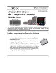
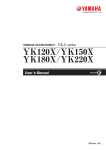
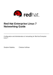
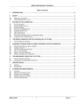
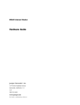
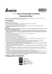
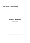
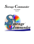
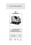
2 General Description
SOLO
Quick Start Guide
3505 HUTCHINSON ROAD
CUMMING, GA 30040-5860
SOLO Temperature Controller
SL9696 Series
This Quick Start Guide provides basic information on setting up the SOLO temperature controller.
For advanced setup and communication control as well as free configuration software visit the
AutomationDirect web site at www.AutomationDirect.com.
Product Support and Configuration Software
• For product support, specifications, and installation troubleshooting, a complete
User Manual can be downloaded from the On-line Documentation area of the
AutomationDirect web site.
• For additional technical support and questions, call our Technical Support team
@ 1-800-633-0405 or 770-844-4200.
• Configuration software for the SOLO controller is available for free download at www.AutomationDirect.com. The software allows communication
and programming for up to four controllers at the same time. Parameters,
process values, set points and temperature changes can be monitored with
the software. The setup data can be uploaded to the user’s PC via RS-485
communication. The user can monitor the temperature changes of the
controllers from the “PV Monitor” Display.
1 Safety Information
WARNING: To minimize the risk of potential safety problems, you should follow all applicable local and
national codes that regulate the installation and operation of your equipment. These codes vary from area to
area and it is your responsibility to determine which codes should be followed, and to verify that the equipment, installation, and operation are in compliance with the latest revision of these codes.
Equipment damage or serious injury to personnel can result from the failure to follow all applicable codes
and standards. We do not guarantee the products described in this publication are suitable for your particular
application, nor do we assume any responsibility for your product design, installation, or operation.
AutomationDirect’s SOLO is a single loop dual output temperature controller that can control both heating and
cooling simultaneously. There are four types of control modes: PID, ON/OFF, Manual, and Ramp / Soak control.
Depending upon the particular model of controller, the available outputs include relay, voltage pulse, current,
and linear voltage. There are up to three alarm outputs available to allow seventeen alarm types in the initial
setting mode. SOLO can accept various types of thermocouple, RTD, or analog inputs, and has a built in RS-485
interface using Modbus slave (ASCII or RTU) communication protocol.
Other features include:
• 1/4 DIN panel size
• 2 line x 4 character 7-segment LED display for Process Value (PV): Red color, and Set Point (SV): Green color
• Auto Tuning (AT) function with PID control
• Selectable between °C and °F for thermocouple or RTD inputs
• Two event inputs
• 0 to 50 °C (32 to 122 °F) operating temperature range
• UL, CUL and CE agency approvals
3 Specifications
Specifications
Input Power Requirements
Operation Voltage Range
Power Consumption
Memory Protection
Control Mode
Input Accuracy
Vibration Resistance
10 to 55 Hz, 10 m/s2 for 10 min, each in X, Y and Z directions
Shock Resistance
Ambient Temperature Range
Storage Temperature Range
Altitude
Relative Humidity
RS-485 Communication
Transmission Speed
Max. 300 m/s2, 3 times in each 3 axes, 6 directions
32°F to 122°F (0°C to 50°C)
-4°F to 149°F (-20°C to 65°C)
2000m or less
35% to 80% (non-condensing)
Modbus slave ASCII / RTU protocol
2400, 4800, 9600, 19.2K, 38.4K bps
IP65: Complete protection against dust and low pressure spraying water from all directions.
(inside suitable enclosure)
UL, CUL, CE (UL file number E311366)
Degree 2 - Normally, only non-conductive pollution occurs.
Temporary conductivity caused by condensation is to be expected.
IP Rating
Agency Approvals
Pollution Degree
Input Types
• Thermocouple*
• Platinum RTD
• Analog
Control Output Options
• Relay (R)
• Voltage Pulse (V)
• Current (C)
• Linear Voltage (L)
EVENT Inputs
• Event1
• Event2
K, J, T, E, N, R, S, B, L, U, TXK (Sampling Rate: 400 ms / per scan)
3-wire Pt100, JPt100 (Sampling Rate: 400 ms / per scan)
0-50 mV, 0-5V, 0-10V, 0-20 mA, 4-20 mA (sinking) (150 ms per scan)**
SPDT max. resistive load 5A @ 250 VAC
DC 14V Max, output current 40mA Max
DC 4-20 mA output (sourcing) (Load resistance: Max 600Ω)
DC 0-10V (Load resistance Min 1KΩ)
Normally open contact, for output control
Normally open contact, for switching setting value
*Note: Use only ungrounded thermocouples.
** Analog input impedance: 1.8MΩ
*Note: T he supplied 249 ohm resistor should be installed as shown in the terminal wiring diagrams
in section 7 for current input operation.
If you have any questions concerning the installation or operation of this equipment, or if you need additional
information, please call us at 1-800-633-0405 or 770-844-4200.
This publication is based on information that was available at the time it was printed. At Automationdirect.
com® we constantly strive to improve our products and services, so we reserve the right to make changes to
the products and/or publications at any time without notice and without obligation. This publication may also
discuss features that may not be available in certain revisions of the product.
100 to 240 VAC 50 / 60 Hz or 24 VDC
85 to 264 VAC or 21.6 to 26.4 VDC
5 VA Max
EEPROM 4K bit, number of writes 100,000
PID, ON/OFF, Ramp / Soak control or Manual
Less than ± 0.2% full scale (except thermocouple R, S, & B types) Max ± 3° (thermocouple R, S, & B types)
Output Specifications
WARNING! Electric shock danger
Part Number
SL9696-RRE
SL9696-VRE
SL9696-CRE
SL9696-LRE
SL9696-RRE-D
SL9696-VVE
SL9696-CVE
1. To prevent electric shock, do not touch the AC terminals while the power is supplied to the controller.
SL9696-LVE
100 - 240 VAC
Linear Voltage
Voltage Pulse
*Output #2 can be configured as control output #2 or as Alarm #3
This controller is an open-type temperature controller. Make sure to evaluate any dangerous application in
which a serious human injury or serious property damage may occur.
1. Always use recommended solder-less terminals: Fork terminal with insolation (M3 screw, width is 7.0mm, hole
diameter 3.2mm). Screw size: M3 x 6.5 (With 6.8 x 6.8 square washer). Recommended tightening torque: 0.4 Nm
(4kgfcm). Applicable wire: Solid/twisted wire of 2 mm, 12AWG to 24AWG. Choose AutomationDirect part numbers
BM-00120, BM-00220 or BM-00320 depending on wire size. Be sure to tighten them properly.
2. Protect the controller from dust or foreign objects to prevent controller malfunction.
Input Voltage
100 - 240 VAC
100 - 240 VAC
100 - 240 VAC
100 - 240 VAC
24 VDC
100 - 240 VAC
100 - 240 VAC
Output #1
Relay - SPDT
Voltage Pulse
Current
Linear Voltage
Relay - SPDT
Voltage Pulse
Current
5. Make sure all wires are connected correctly.
Alarm #1
Relay - SPST
Relay - SPST
Relay - SPST
Relay - SPST
Relay - SPST
Relay - SPST
Relay - SPST
Alarm #2
Relay - SPST
Relay - SPST
Relay - SPST
Relay - SPST
Relay - SPST
Relay - SPST
Relay - SPST
Relay - SPST
Relay - SPST
4 Box Contents and Unpacking Instructions
•U
npack the SOLO temperature controller from its shipping carton. Included in the carton is the temperature
controller, mounting brackets plus hardware and this Quick Start Guide.
• I nspect all equipment for completeness. If anything is missing or damaged, immediately call the
AutomationDirect returns department @ 1-800-633-0405.
• Inspect the part number to ensure the model received matches the output type required.
3. Do not modify or disassemble the controller.
4. Do not connect anything to the “Not used” terminals.
Output #2 / Alarm #3*
Relay - SPDT
Relay - SPDT
Relay - SPDT
Relay - SPDT
Relay - SPDT
Voltage Pulse
Voltage Pulse
Mounting Brackets
and Hardware
16 18
SL9696 Temperature
Controller
6. Do not install and/or use the controller in places subject to: (a) Dust or corrosive gases and liquid (b) High humidity
(c) Vibration and shock (d) EMI / RFI (e) high temperature.
7. Turn power off when wiring or changing a temperature sensor.
8. Be sure to use wires that match the thermocouple types when extending or connecting the thermocouple wires.
9. Use wires with correct resistance when extending or connecting a platinum resistance thermometer (RTD).
249 ohm
resistor
10. Keep the wire as short as possible when wiring a platinum resistance thermometer (RTD) to the controller and
route power wires as far as possible from load wires to prevent interference and induced noise.
SL9696
Quick Start Guide
11. This controller is an open-type unit and must be placed in an enclosure away from high temperature, humidity,
dripping water, corrosive materials, airborne dust and electric shock or vibration.
13. To prevent electric shock, do not touch the terminals in the controller or try to repair the controller when power
is applied.
5 Controller and Panel Cutout Dimensions
15. This instrument is not furnished with a power switch or fuse. Therefore, if a fuse or power switch is required,
install the protection close to the instrument. Recommended fuse rating: Rated voltage 250 V, Rated current 1
A. Fuse type: Time-lag fuse
16. Note: This controller does not provide overcurrent protection. Use of this product requires that suitable overcurrent protection device(s) must be added to ensure compliance with all relevant electrical standards and codes.
(Rated 250 V, 15 Amps max). A suitable disconnecting device should be provided near the controller in the
end-use installation.
4.33" (Min)
[110.0 mm]
3.57”
(90.8 mm)
14. Use a soft, dry cloth to clean the controller. Do not use acid or alkaline liquids for cleaning.
PV
F
C
3.57”
(90.8 mm)
OUT1 OUT2 ALM1 ALM2 ALM3
3.78”
(96.0 mm)
AT
3.86”
(98.0 mm)
SV
SET
3.58" +0.02
-0
[90.9 mm] +0.6
-0
3.58" +0.02
-0
[90.9 mm] +0.6
-0
SOLO 9696
3.78”
(96.0 mm)
4.33" (Min)
[110.0 mm]
12. Make sure power cables and signals from instruments are all installed properly before energizing the controller,
otherwise serious damage may occur.
0.62”
(15.88 mm)
3.12”
(79.2 mm)
6 Mounting Instructions
8 Display, LED and Key Pad
SOLO temperature controllers can be mounted through a cutout in an enclosure or panel by using the dimensions shown in Section 5. The directions for mounting the controller through a cutout are:
PV Display: To display the process value or parameter type.
PV
SV Display: To display the set point, parameter operation read value
manipulated variable or set value of the parameter.
1. Insert the temperature controller through the panel cutout.
2. Slide the M3X0.5 nut into the opening in the top of the mounting bracket and insert the M3X0.5 X 30mm
mounting screw in the mounting bracket.
3. Insert the mounting brackets into the mounting groove at the top and bottom of the controller, and push the
mounting bracket forward until the bracket stops.
4. Tighten top and bottom screws evenly to secure temperature controller in place.
2
AT: Auto-tuning LED, flashes when the Auto-tuning operation is ON.
SV
OUT1 / OUT2: Output LED, lights when the output is ON.
AT
OUT1 OUT2 ALM1 ALM2 ALM3
F
C
ALM1 / ALM2 / ALM3: Alarm output LED, lights when that alarm is on.
°C, °F: Temperature unit LED. °C: Celsius °F: Fahrenheit
SET
Set Button: Press this key to select the desired function mode and
confirm the setting value.
SOLO 9696
4
3
Rotate Button: Press this key to select parameters within the function
mode.
Down Button: Press this key to decrease values displayed on the SV
display. Hold down this key to speed up the decrement.
Up Button: Press this key to increase values displayed on the SV
display. Hold down this key to speed up the increment.
9 Key Pad Operation
1
7 Terminal Identification
Regulation
Mode
WARNING! Electric shock danger
To prevent electric shock, do not connect AC power to your device until all input and output
connections are completed.
SL9696-RRE
SET
Hold for 3 sec.
SET
Press for less
than 3 sec.
SL9696-LRE & SL9696-VRE
Initial Setting
Mode
Operation Mode
SET
SET
Regulation
Parameters
Operation
Parameters
Initial Setting
Parameters
The SOLO temperature controller has three function modes: Initial Setting mode, Operation mode and Regulation
mode. When power is first applied to the temperature controller, the module information splash screen appears.
This screen shows the firmware version on the PV display and the two output types for that particular model on
the SV display. After three seconds, the controller will automatically proceed to the Operation mode main screen.
Press and hold the ; button for three seconds to go into the Initial Setting mode. Press the ; button for less
than three seconds to access the Regulation mode. Press the • button while inside any of the three function
modes to access the individual parameters for each function mode. Use the . and , buttons to change the
individual parameter values. Pressing the ; button saves the parameter values. Press the ; button again
to return the controller to the Operation mode.
10 Reset to Factory Default Instructions
SL9696-CRE
SL9696-LVE
All of the following set up instructions are for setting up a controller from the factory defaults. If the
application for a controller needs to be changed, reset the controller to factory default using the following
steps.
1. Press the • button until the parameter
; button.
loC appears. Use the . button to select loC1. Press the
2. Press and hold the , and . buttons simultaneously for one second and release.
3. Press the • button repeatedly until the PV display shows pass. Use the , button to change the value
on the SV display to 1357. Press the ; button.
4. Cycle power on the Controller to reset to factory default mode. All user set values are erased.
11-1 Thermocouple or RTD Input
SL9696-VVE
SL9696-CVE
1. Access the Initial Setup mode by pressing and holding the ; button for three seconds. In the parameter
inpt, use the , and . buttons to select the value that corresponds to the thermocouple or RTD type
that will be attached to the controller. See the table below for specifications. Press the ; button to save the
selected value. The controller will display the module information splash screen for three seconds and then
return to the main screen.
2. Press the ; button for three seconds again. Press the • button to access the tpun parameter. Use
the , and . buttons to select either C for Centigrade or f for Fahrenheit display. Press the ; button
to save the selected value. The controller will display the module information splash screen for three seconds
and then return to the main screen.
3. Press the ; button for three seconds again. Press the • button repeatedly until the tp-H parameter
appears. Use the , and . buttons to set the maximum value of the operational temperature range. In
operation, if the PV value is higher than the TP-H value, the PV display flashes to indicate an error and the
controller outputs shut off. The SV value cannot exceed the TP-H value. Press the ; button to save the
selected value. Press the • button to access the tp-l parameter. Use the , and . buttons to set
the minimum value of the operational temperature range. In operation, if the PV value is lower than the TP-L
value, the PV display flashes to indicate an error and the controller outputs shut off. The SV value cannot be set
lower than the TP-L value. Press the ; button twice to save the selected value and return to the controller
main screen.
Power Input
Sensor Input
0 – 10 VDC
4 – 20 mA
AC Powered
Models
4. Press the • button repeatedly until the parameter sp appears. Use the , and . buttons to select
either 0 for a whole degree or 1 for a tenth degree temperature display.* Press the ; button twice to save
the selected value and return to the controller main screen.
5. If the input temperature from the thermocouple or RTD needs to be adjusted, press the ; button for less
than 3 seconds. Press the • button repeatedly until the parameter tpof appears. Use the , and .
buttons to adjust a positive or negative offset to the PV value displayed on the controller. Press the ; button
twice to save the selected value and return to the controller main screen.
*Note: The decimal point display cannot be adjusted for B, S, and R type thermocouples.
Thermocouple* Type and Temperature Range
Input Temperature Sensor Type
Thermocouple TXK type
Thermocouple U type
Thermocouple L type
DC Powered
Models
2-wire RTD
24 VDC power for models with
–D suffix only
Thermocouple B type
Thermocouple S type
Thermocouple R type
Thermocouple N type
Thermocouple E type
Thermocouple T type
Thermocouple J type
Thermocouple
3-wire RTD
Thermocouple K type
LED Display
txk
u
l
b
s
r
n
e
t
j
k
Temperature Range
-328 ~ 1472°F (-200 ~ 800°C)
-328 ~ 932°F (-200 ~ 500°C)
-328 ~ 1562°F (-200 ~ 850°C)
-212 ~ 3272°F (100 ~ 1800°C)
32 ~ 3092°F (0 ~ 1700°C)
32 ~ 3092°F (0 ~ 1700°C)
-328 ~ 2372°F (-200 ~ 1300°C)
32 ~ 1112°F (0 ~ 600°C)
-328 ~ 752°F (-200 ~ 400°C)
-148 ~ 2192°F (-100 ~ 1200°C)
-328 ~ 2372°F (-200 ~ 1300°C)
RTD Type and Temperature Range
Input Temperature Sensor Type
Platinum Resistance (Pt100)
Platinum Resistance (JPt100)
*Note: Use only ungrounded thermocouples.
LED Display
pt
jpt
Temperature Range
-328 ~ 1112°F (-200 ~ 600°C)
-4 ~ 752°F (-20 ~ 400°C)
11-2 Voltage Input
12-3 Heating Loop with ON / OFF Control
1. Access the Initial Setup mode by pressing and holding the ; button for three seconds. In the parameter
inpt, use the , and . buttons to select the value that corresponds to the voltage input that will be
applied to the controller. See the table for voltage specifications. Press the ; button to save the selected
value. The controller will display the module information splash screen for three seconds and then return to
the main screen.
2. Press the ; button for three seconds again. Press the • button to access the parameter tp-h.
Use the , and . buttons to select the high engineering value that corresponds to the maximum voltage
signal that will be applied to the input of the controller. For example, if the V5 0V-5V input is to be used, this
is the value the controller will display when the input equals 5V. Press the ; button to save the selected
value. Press the • button to access the parameter tp-l. Use the , and . buttons to select the
low engineering value that corresponds to the minimum voltage signal that will be applied to the input of the
controller. For example, if the V5 0V-5V input is to be used, this is the value the controller will display when the
input equals 0V. Press the ; button twice to save the selected value and return to the controller main screen.
3. Press the • button repeatedly until the parameter sp appears. Use the , and . buttons to select
0, 1, 2 or 3 to indicate the position of the decimal point for the PV and SV values on the controller. Press the
; button twice to save the selected value and return to the controller main screen.
4. If the voltage input PV value displayed on the controller needs to be adjusted, press the ; button for less
than 3 seconds. Press the • button repeatedly until the parameter tpof appears. Use the , and .
buttons to adjust a positive or negative offset to the PV value displayed on the controller. Press the ; button
twice to save the selected value and return to the controller main screen.
Voltage Input Type
LED Display
Engineering Range
-999 ~ 9999
mv
v10
v5
0V~10V Analog Input
0V~5V Analog Input
2. Press the • button to access the parameter r-s. Verify that the default value
the ; button to return to the controller main screen.
run is selected. Press
3. Press the ; button for less than three seconds to access the parameter hts. Use the , and .
buttons to enter hysteresis. This is the amount the PV must go below the SV before the controller output turns
on. Press the ; button twice to save the selected value and return to the controller main screen.
12-4 Cooling Loop with PID Control
1. Access the Initial Setup mode by pressing and holding the ; button for three seconds. Press the •
button repeatedly until the parameter Ctrl appears. Confirm the default value Pid is selected for PID
control. Press the • button to access the parameter s-hC. Use the . button to select Cool for
controlling a cooling loop. Press the ; button twice to save the value and return to the controller main screen.
2. Press the • button to access the parameter r-s. Verify that the default value
the ; button to return to the controller main screen.
run is selected. Press
3. Refer to Section 12-1 of this Quick Start Guide to set up the PID control parameters.
Voltage Input Type and Input Range
0~50mV Analog Input
1. Access the Initial Setup mode by pressing and holding the ; button for three seconds. Press the •
button repeatedly until the parameter Ctrl appears. Use the , and . buttons to select onof for ON
/ OFF control. Press the ; button to save the value. Press the • button to access the parameter s-hC.
Confirm the default value heat is selected for controlling a heating loop. Press the ; button to return to
the controller main screen.
-999 ~ 9999
4. If the temperature controller’s output #1 is discrete, access the regulation mode again by pressing the ;
button for less than three seconds. Press the • button repeatedly until the parameter Clpd appears. Use
the , and . buttons to set the time period in seconds for the cooling control. Press the ; button twice
to save the value and return to the controller main screen.
-999 ~ 9999
12-5 Cooling Loop with ON / OFF Control
11-3 Current Input
1. Install the supplied 249 ohm resistor between terminal #9 and #10.
2. Access the Initial Setup mode by pressing and holding the ; button for three seconds. In the parameter
inpt, use the , and . buttons to select the value that corresponds to the current input that will be
applied to the controller. See the table for current specifications. Press the ; button to save the selected
value. The controller will display the module information splash screen for three seconds and then return to the
main screen.
3. Press the ; button for three seconds again. Press the • button repeatedly until the parameter tp-h
appears. Use the , and . buttons to select the high engineering value that corresponds to the maximum
current signal that will be applied to the input of the controller. For example, if the ma4 4-20mA input is to be
used, this is the value the controller will display when the input equals 20mA. Press the ; button to save
the selected value. Press the • button to access the parameter tp-l. Use the , and . buttons
to select the low engineering value that corresponds to the minimum current signal that will be applied to the
input of the controller. For example, if the ma4 4-20mA input is to be used, this is the value the controller will
display when the input equals 4mA. Press the ; button twice to save the selected value and return to the
controller main screen.
4. Press the • button repeatedly until the parameter sp appears. Use the , and . buttons to select
0, 1, 2 or 3 to indicate the position of the decimal point for the PV and SV values on the controller. Press the
; button twice to save the selected value and return to the controller main screen.
5. If the current input PV value displayed on the controller needs to be adjusted, press the ; button for less
than 3 seconds. Press the • button repeatedly until the parameter tpof appears. Use the , and .
buttons to adjust a positive or negative offset to the PV value displayed on the controller. Press the ; button
twice to save the selected value and return to the controller main screen.
Current Input Type and Range
Current Input Type
LED Display
4~20mA Analog Input
0~20mA Analog Input
ma4
ma0
Engineering Range
-999 ~ 9999
-999 ~ 9999
12-1 PID Control Setup
Note: Select the desired control mode before beginning PID Control Setup.
There are four groups for storing PID parameters, pid0 (PID0) - pid3 (PID3). Press the ; button for
less than three seconds and press the • button repeatedly until the parameter pid0 appears. Use the
, and . buttons to select which group to use for storing the PID parameters. Press the ; button to
confirm the setting. The groups pid0 - pid3 can be individually set up with different SV values to be used
in the control process. If the group pid4 is selected, the controller will automatically select the most useful
PID parameters based on the current temperature setting and the SV value set in each PID group.
The parameters for PID can be auto-tuned using the
parameter. Access this parameter by pressing the
At
; button for less than three seconds. Use the . button to turn the auto-tune feature on. Press the ;
button to save the value. Optimal PID values are automatically determined with the auto-tune feature. PID
operation can also be controlled by programming the individual
p, i, and d parameters for each PID group.
Access these parameters by pressing the ; button for less than three seconds and press the • button
repeatedly until the parameter pn appears where n corresponds to the PID group you are programming. Use
the , and . buttons to change the value for the Proportional band if desired and press the ; button to
save the value. Press the • button to access the in parameter. Use the , and . buttons to change
the value for the Integral time if desired and press the ; button to save the value. Press the • button to
access the dn parameter. Use the , and . buttons to change the value for the Derivative time if desired
and press the ; button twice to save the value and return to the controller main screen.
12-2 Heating Loop with PID Control
1. Access the Initial Setup mode by pressing and holding the ; button for three seconds. Press the •
button repeatedly until the parameter Ctrl appears. Confirm the default value Pid is selected for PID
control. Press the • button to access the parameter s-hC. Confirm the default value heat is selected for controlling a heating loop. Press the ; button to return to the controller main screen.
2. Press the • button to access the parameter r-s. Verify that the default value
the ; button to return to the controller main screen.
run is selected. Press
3. Refer to Section 12-1 of this Quick Start Guide to set up the PID control parameters.
4. If the temperature controller’s output #1 is discrete, access the regulation mode again by pressing the ;
button for less than three seconds. Press the • button repeatedly until the parameter htpd appears. Use
the , and . buttons to set the time period in seconds for the heating control. Press the ; button twice
to save the value and return to the controller main screen.
1. Access the Initial Setup mode by pressing and holding the ; button for three seconds. Press the •
button repeatedly until the parameter Ctrl appears. Use the , and . buttons to select onof for ON
/ OFF control. Press the ; button to save the value. Press the • button to access the parameter s-hC.
Use the . button to select Cool for controlling a cooling loop. Press the ; button twice to save the
value and return to the controller main screen.
2. Press the • button to access the parameter r-s. Verify that the default value run is selected. Press
the ; button to return to the controller main screen.
3. Press the ; button for less than three seconds to access the parameter Cts. Use the , and .
buttons to enter hysteresis. This is the amount the PV must go above the SV before the controller output turns
on. Press the ; button twice to save the selected value and return to the controller main screen.
12-6 Dual Heating / Cooling Loop with PID Control
1. Access the Initial Setup mode by pressing and holding the ; button for three seconds. Press the •
button repeatedly until the parameter Ctrl appears. Confirm the default value Pid is selected for PID
control. Press the • button to access the parameter s-hC. Use the . button to select h1C2 for
controlling a dual heating / cooling loop. This parameter sets the heating control to output #1 and the cooling
control to output #2. Press the ; button twice to save the value and return to the controller main screen.
2. Press the • button to access the parameter r-s. Verify that the default value run is selected. Press
the ; button to return to the controller main screen.
3. Refer to Section 12-1 of this Quick Start Guide to set up the PID control parameters.
4. If the temperature controller’s output #1 is discrete, access the regulation mode again by pressing the ;
button for less than three seconds. Press the • button repeatedly until the parameter htpd appears. Use
the , and . buttons to set the time period in seconds for output #1, the heating control. Press the ;
button to save the value. If the temperature controller’s output #2 is discrete, press the • button repeatedly
until the parameter hCpd appears. Use the , and . buttons to enter the cycle period in seconds for
output #2, the cooling output. Press the ; button twice to save the value and return to the controller main
screen.
5. Optional regulation parameters can be programmed for a second control
output. If this is desired, access the regulation mode again by pressing the
; button for less than three seconds. Press the • button repeatedly
until the parameter Coef appears. This value allows the cooling control
to have a different proportional setting than the heating loop. The heating
loop proportional band setting is multiplied by the Coef value to create
a proportional band setting for the cooling loop control. Use the , and
. buttons to change this value if desired. Press the ; button to
save the selected value. Press the • button to access the parameter
dead. Use the , and . buttons to enter a deadband zone value
around the setpoint where the output is not effected by the proportional
control value. As long as the PV remains within the deadband zone the
output is not affected by the proportional control. The integral and derivative controls ignore the deadband setting and may cause the output to
be on within the deadband zone. Press the ; button twice to save the
value and return to the controller main screen.
dead
Dead band: dead
band width=positive
Output
Heating
0
Cooling
PV
Set point
Dual control with PID
positive deadband
dead
Dead band: dead
band width=negative
Output
Heating
0
Cooling
PV
Set point
Dual control with PID
negative deadband
12-7 Dual Heating / Cooling Loop with ON / OFF Control
1. Access the Initial Setup mode by pressing and holding the ; button for three seconds. Press the •
button repeatedly until the parameter Ctrl appears. Use the , and . buttons to select onof for
ON / OFF control and press the ; button to save the selected value. Press the • button to access the
parameter s-hC. Use the . button to select h1C2 for controlling a cooling / heating loop. This parameter
sets the heating control to output #1 and the cooling control to output #2. Press the ; button twice to save
the value and return to the controller main screen.
2. Press the • button to access the parameter r-s. Verify that the default value run is selected. Press
the ; button to return to the controller main screen.
3. Press the ; button for less than three seconds to access the
parameter hts. Use the , and . buttons to enter hysteresis
for output #1, the heating control. This is the amount the PV must go
below the SV before the controller output turns on. Press the ;
button to save the selected value. Press the • button to access
the parameter Cts. Use the , and . buttons to enter hysteresis for output #2, the cooling control. This is the amount the PV
must go above the SV before the controller output turns on. Press
the ; button twice to save the selected value and return to the
controller main screen.
dead
Dead band
hts
Heating hysteresis
Cts
Cooling hysteresis
ON
Heating
Cooling
OFF
PV
Set point
Dual loop ON / OFF control
output operation
4. Optional regulation parameters can be programmed for additional dual loop control. If this is desired, access
the regulation mode again by pressing the ; button for less than three seconds. Press the • button
repeatedly until the parameter dead appears. Use the , and . buttons to enter a deadband zone
value around the setpoint where the output is not on. The PV must go beyond the deadband range in order for
either the heating or cooling output to turn on. Press the ; button twice to save the selected value and return
to the controller main screen.
12-8 Dual Cooling / Heating Loop with PID Control
12-11 Manual Control Setup
1. Access the Initial Setup mode by pressing and holding the ; button for three seconds. Press the •
button repeatedly until the parameter Ctrl appears. Confirm the default value Pid is selected for PID
control. Press the • button to access the parameter s-hC. Use the . button to select h2C1 for
controlling a dual cooling / heating loop. This parameter sets the cooling control to output #1 and the heating
control to output #2. Press the ; button twice to save the value and return to the controller main screen.
2. Press the • button to access the parameter r-s. Verify that the default value run is selected. Press
the ; button to return to the controller main screen.
3. Refer to Section 12-1 of this Quick Start Guide to set up the PID control parameters.
4. If the temperature controller’s output #1 is discrete, access the regulation mode again by pressing the ;
button for less than three seconds. Press the • button repeatedly until the parameter Clpd appears. Use
the , and . buttons to set the time period in seconds for the cooling output control. Press the ; button
to save the value. If the temperature controller’s output #2 is discrete, press the • button repeatedly until the
parameter hCpd appears. Use the , and . buttons to enter the cycle period for output #2, the heating
output. Press the ; button twice to save the value and return to the controller main screen.
5. Optional regulation parameters can be programmed for additional
dual loop control. If this is desired, access the regulation mode again
by pressing the ; button for less than three seconds. Press the •
button repeatedly until the parameter Coef appears. This value allows
the heating control to have a different proportional setting than the cooling
loop. The cooling loop proportional band setting is multiplied by the
Coef value to create a proportional band setting for the heating loop
control. Use the , and . buttons to change this value if desired.
Press the ; button to save the selected value. Press the • button to
access the parameter dead. Use the , and . buttons to enter a
deadband zone value around the setpoint where the output is not effected
by the proportional control value. As long as the PV remains within the
deadband zone the output is not affected by the proportional control. The
integral and derivative controls ignore the deadband setting and may
cause the output to be on within the deadband zone. Press the ;
button twice to save the value and return to the controller main screen.
dead
Dead band: dead
band width=positive
Output
Heating
0
Cooling
Set point
dead
Dead band: dead
band width=negative
Heating
0
Cooling
PV
Set point
Dual loop PID control
negative deadband
1. Access the Initial Setup mode by pressing and holding the ; button for three seconds. Press the •
button repeatedly until the parameter Ctrl appears. Use the , and . buttons to select onof for
ON / OFF control and press the ; button to save the selected value. Press the • button to access the
parameter s-hC. Use the . button to select h2C1 for controlling a cooling / heating loop. This parameter
sets the cooling control to output #1 and the heating control to output #2. Press the ; button twice to save
the value and return to the controller main screen.
2. Press the • button to access the parameter r-s. Verify that the default value run is selected. Press
the ; button to return to the controller main screen.
Dead band
hts
EVENT1 input is a normally open contact input that controls the output(s) of the controller. All controller outputs
are disabled when an external contact for EVENT1 is closed.
14 Alarm Outputs
The alarm output limits are controlled by the parameters Alnh and Alnl, where “n” corresponds to the
alarm output group chosen. After selecting the desired alarm group(s), press the • button repeatedly until
the parameter Alnh and/or Alnl appears. Use the . and , buttons to enter the high and/or low
values for each group of alarm outputs selected. Press the ; button to save each selected value. Press the
; button again to return to the controller main screen.
ALA1 and ALA2 are both SPST resistive load 3A @ 250 VAC, normally open relay outputs. ALA3 uses the same
output as output #2 and is the same type of output.
*Note: When output #2 is used, ALA3 is disabled. ALA3 is available only for single output loop control.
Set Value
0
dead
Heating hysteresis
13 Event Inputs
Two event inputs are available with the SL-9696 series temperature controller. (See section 8 for terminal wiring)
There are up to three groups of alarm outputs (ALA1, ALA2, ALA3*). Each alarm group can be programmed for
one of seventeen different alarm types. To set up the first alarm output, press the ; button for three seconds.
Press the • button repeatedly until the parameter ALA1 appears. Use the . button to choose the set
value for the desired alarm type. Refer to the chart below for alarm type information. Press the ; button to
save the selected value. If additional alarm outputs are required press the • button to proceed to ALA2
and/or ALA3 *. Follow the same procedure to program these additional alarms. When the desired alarms are
programmed, press the ; button repeatedly until the controller returns to the main screen.
12-9 Dual Cooling / Heating Loop with ON / OFF Control
3. Press the ; button for less than three seconds to access the
parameter hts. Use the , and . buttons to enter hysteresis
for output #2, the heating control. This is the amount the PV must go
below the SV before the controller output turns on. Press the ;
button to save the selected value. Press the • button to access
the parameter Cts. Use the , and . buttons to enter hysteresis for output #1, the cooling control. This is the amount the PV must
go above the SV before the controller output turns on. Press the ;
button twice to save the selected value and return to the controller
main screen.
2. Press the • button to access the parameter out1. Use the , and . buttons to set a value
between )0 and 10)0 to control output #1 directly. If the controller has a discrete output, a value of 2)0
turns the output on 20% of the time. A value of 10)0 would turn the output on 100% of the time. A manually
controlled analog output value is a percentage of the analog signal. For example, if the controller has a 4-20mA
current output, a setting of )0 would mean that the output would be 4mA. The output would be 20mA with a
setting of 10)0. Both types of manually controlled outputs are off with a value of 00. Press the ; button
to save the selected value. For dual output control, press the • button to access the parameter out2. Use
the , and . buttons to set a value between )0 and 10)0 to control output #2 directly. Press the ;
button twice to save the selected value and return to the controller main screen.
EVENT2 input is a normally open contact input that switches the setting value between two different values
based on the state of the EVENT2. If the contact is open the first setting value is used for all parameters and
outputs. If the contact is closed the second setting value is used for all parameters and outputs. Each temperature setting value has individual control parameters.
PV
Dual loop PID control
positive deadband
Output
1. Access the Initial Setup mode by pressing and holding the ; button for three seconds. Press the •
button repeatedly until the parameter Ctrl appears. Use the , and . buttons to select manu for
manual control. Press the ; button twice to save the selected value and return to the controller main screen.
Cts
Cooling hysteresis
1
ON
Heating
Cooling
OFF
PV
2
Set point
Dual loop ON / OFF control
output operation
3
4
4. Optional regulation parameters can be programmed for additional dual loop control. If this is desired, access
the regulation mode again by pressing the ; button for less than three seconds. Press the • button
repeatedly until the parameter dead appears. Use the , and . buttons to enter a deadband zone
value around the setpoint where the output is not on. The PV must go beyond the deadband range in order for
either the heating or cooling output to turn on. Press the ; button twice to save the selected value and return
to the controller main screen.
12-10 Ramp / Soak Control
5
2. The chart below illustrates an example of a seven step Ramp / Soak pattern (Pattern 0). Press the • button
to access the parameter SP00. Use the , and . buttons to select a setting value temperature for step
00 and press the ; button to save the value. Press the • button to access the parameter ti00. Use
the , and . buttons to enter a time in hours / minutes for step 00. Follow this procedure until the desired
number of temperature and time parameters are completed. Press the • button to access the parameter
psx0. Use the , and . buttons to select the last step to be completed by the Ramp /Soak pattern. For
example, if psx0 is set to 4, steps 00 through 04 will be executed in the pattern.
3. Press the • button to access the parameter CYC0. Use the , and . buttons to select the number
of additional times the Ramp / Soak pattern will be executed. For example, if CyC0 is set to 3, the Ramp /
Soak pattern will execute a total of four times. Press the ; button to save the selected value. Press the •
button to access the parameter lin0. Use the , and . buttons to choose a Ramp / Soak pattern to
execute after the completion of Pattern 0. If set to off, the temperature of the last step in Pattern 0 will be held.
Press the ; button twice to save the selected value and return to the controller main screen.
Alarm Output Operation
6
Absolute value upper-limit:
This alarm output activates when the PV value is higher than the setting value ALnH
7
Absolute value lower limit:
This alarm output activates when the PV value is lower than the setting value ALnL
13
Deviation upper and lower limit with standby sequence:
This alarm output activates when the PV value reaches the set point (SV value) and the reached value
is higher than the setting value SV + ALnH or lower than the setting value SV - ALnL.
Deviation upper limit with standby sequence:
This alarm output activates when the PV value reaches the set point (SV value) and the reached
value is higher than the setting value SV+ ALnH.
Deviation lower limit with standby sequence:
This alarm output activates when the PV value reaches the set point (SV value) and the reached
value is lower than the setting value SV - ALnL.
Hysteresis upper-limit alarm output:
This alarm output activates when the PV value is higher than the setting value
SV + ALnH. This alarm output is OFF when the PV value is lower than the setting value SV + ALnL.
Hysteresis lower-limit alarm output:
This alarm output activates when the PV value is lower than the setting value
SV- ALnH. This alarm output is OFF when the PV value is higher than the setting value SV - ALnL.
N/A
14
15
16
17
18
This alarm activates when the Ramp / Soak program has ended.
This alarm activates while the program is in RAMP UP status.
This alarm activates while the program is in RAMP DOWN status.
This alarm activates while the program is in SOAK status.
This alarm activates while the program is in RUN status.
8
1. Access the Initial Setup mode by pressing and holding the ; button for three seconds. Press the •
button repeatedly until the parameter Ctrl appears. Use the , and . buttons to select pro6 for
Ramp / Soak control. Press the ; button to save the selected value. Press the • button to access the
parameter Patn. Eight different Ramp / Soak patterns are possible with the Solo Temperature Controller.
Use the , and . buttons to select pattern number 0 through 7 for programming. Press the ; button
to save the selected value.
Alarm Type
Alarm function disabled
Output is OFF
ON
Deviation upper and lower limit:
OFF
This alarm output activates when the PV value is higher than the setting value
SV - ALnL SV
SV + ALnH or lower than the setting value SV - ALnL.
ON
Deviation upper-limit:
OFF
This alarm output activates when the PV value is higher than the setting value
SV
SV + ALnH.
ON
Deviation lower limit:
OFF
This alarm output activates when the PV value is lower than the setting value
SV - ALnL.
SV - ALnL SV
ON
Reverse deviation upper and lower limit:
OFF
This alarm output activates when the PV value is in the range of the setting value
SV - ALnL SV
SV+ ALnH and the setting value SV - ALnL.
ON
Absolute value upper and lower limit:
OFF
This alarm output activates when the PV value is higher than the setting value ALnH or lower than
ALnL
the setting value ALnL.
9
10
11
12
SV + ALnH
SV+ALnH
SV + ALnH
ALnH
ON
OFF
ALnH
ON
OFF
ALnL
ON
OFF
SV - ALnL
SV SV + ALnH
ON
OFF
SV
SV + ALnH
ON
OFF
SV - ALnL SV
ON
OFF
SV SV + ALnL SV + ALnH
ON
OFF
SV - ALnH
SV - ALnL SV
Ramp / Soak Program Alarms
Note: ALnH includes AL1H, AL2H and AL3H. ALnL includes AL1L, AL2L and AL3L.
15 Error Display Information
The chart below shows the possible error displays on the Solo temperature controller.
Ramp
Controller Error Display
08.00
100°
70°
03.00
50°
30°
Soak
POS0
05.00
03.00
02.00
05.00
03.00
POS1
POS2
POS3
POS4
POS5
POS6
Display Position
Display
PV
b160
Cr
SV
PV
SV
PV
SP00 Step00 = 50°
ti00 Time00 = 3 hrs 00 min.
SP01 Step01 = 70°
ti01 Time01 = 2 hrs 00 min.
SP02 Step02 = 70°
ti02 Time02 = 5 hrs 00 min.
SP03 Step03 = 100°
ti03 Time03 = 3 hrs 00 min.
SP04 Step04 = 100°
ti04 Time04 = 8 hrs 00 min.
SP05 Step05 = 30°
ti05 Time05 = 5 hrs 00 min.
SP06 Step06 = 30°
ti06 Time06 = 3 hrs 00 min.
psx0 Process Step = 6
CyCO Cycle times = 0
lin0 Link = OFF
SV
PV
SV
PV
SV
no
Cont
Err
Inpt
Err
Prom
Flashing PV
Meaning
Cause
Initialization
The controller is
PV = Firmware version in the initialization
SV = Module type
process.
No sensor input
Corrective Action
The Solo controller displays this information for a few seconds after power up. If the controller continues
displaying this information, check the input wiring. If the
problem still exists, replace the sensor or the controller.
The input terminals Check the input wiring. If the problem still exists, replace the
are open.
sensor or the controller.
Input error
The controller cannot
read the input value
Check the sensor and the input wiring. If the problem still
exists, replace the sensor or the controller.
EEPROM error
There is an error with
the EEPROM
Cycle the power to the Solo controller. If the problem still
exists, replace the controller.
PV out of range
The PV is out of
range
Check the PV range. The parameters tp-h and tp-l
define the range. Refer to section 12-1, 12-2 or 12-3 for
directions on how to access these parameters.