1
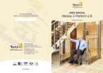
USER MANUAL Melody 1 Platform Lift Original instructions CONTENTS PAGE Introduction Description General Do’s and Don’ts Controls Operating the Lift Emergency Procedures Platform Gate Lock Maintenance Fault Finding Safety Feature Checks Service History Record Declaration of Conformity Lift specification sheet 4 4 6 7 8 9 10 12 13 14 15 16 17 3 Introduction Thank you for choosing the Terry Melody 1 lift, designed and manufactured in the U.K. using the latest technology from Terry Group Ltd. We want you to get the most out of your Melody 1 Lift and to help in this aim, we have produced this small booklet on operation and maintenance of the equipment which we trust you will find helpful. It is hoped that any queries you may have during day to day operation will be answered in the text but if you do have any problems our technical help service is only a ‘phone call away. We hope that our product gives you many years of reliable service. Peter Morrey Managing Director Description The Terry Melody 1 Lift is designed to transport a disabled person with or without a wheelchair between two floor levels up to 1 metre apart. To provide the lifting force the lift uses a hydraulic cylinder under the platform, fed via a hose from a pump unit mounted under the power pack cover on the platform. Principal features of the design are its low closed height and silent smooth operation. The low closed height eliminates the need for a pit. Control stations are provided on the platform handrail and at the upper and/or lower levels depending on requirements. A remote control enabler or isolate option is also available to limit the use of the lift to authorised users only. 4 Optional upper level gate Platform gate Control handrail Power pack Ground ramp It is most important that before operating the lift you read these instructions fully and are familiar with the controls and operating procedure. Domestic Access Lifts If a change of use of the lift is required, this should be discussed with the manufacturer/supplier as certain alterations may be needed. Examples of changes of use are: a) change of type, size and/or weight of wheelchair; b) change of user disability; c) change of user; d) removal of the homelift and reinstallation at another site; e) change of duty cycle. All changes of use should entail a review of the installation. 5 General do’s and don’ts Always leave the power supply to the lift left on, even when you go away. The lift control circuits are fed by a battery, which must be kept on constant charge Never allow children to play on or around the lift. Ensure that the area around the lift is kept clear from debris (e.g. litter and leaves). Do not exceed the maximum lifting capacity of 39 stone (250 kg). Always treat your lift with respect that should be shown to electrical and mechanical equipment. WARNING! As recommended by the Medicines and Healthcare products Regulatory Agency (MHRA), great care should be exercised whilst manoeuvring on and off the platform ramp, to avoid the risk of tipping over rearwards. Information can be found at www.mhra.gov.uk 6 Controls Location Call stations are on the upper level gate as standard and on the ramp post at the lower level as standard. Each call station incorporates seperate ‘up and down’ controls and a ‘gate open’ button. A control panel is mounted on the lift platform, incorporating seperate ‘up’ and ‘down’ controls, a ‘gate open’ button and ‘alarm’ button. Function All controls are of the “hold to run” type. Maintain pressure on the button during lift travel. The lift automatically stops when it reaches it’s destination. A master switch, which “locks” all controls to prevent unauthorised use is fitted to the charger box. If the lift has been supplied with a remote control lift enabler or isolate unit the lift will remain disabled until key fob is pressed. Pressing the key fob will allow the lift to be operated by the up/down control in the normal way. Enabler: 3 minutes after pressing the key fob the lift will automatically revert back to its disabled mode preventing further use. The lift can then only be reactivated for use by repressing the key fob. Isolate: Press the key fob again to disable the lift. The lift can then only be reactivated for use by repressing the key fob. 7 Operating the Lift If the radio control enabler option is fitted press the key fob to activate the control stations. If necessary call the lift by maintaining pressure on the call button and wait for it to stop at the appropriate level. Move on to the platform and apply the wheelchair brakes. Press and maintain pressure on the up or down control button to operate the lift until it stops at the required level. When the button is released, a chime will sound to signal that the gate can be opened. The upper level gate will automatically release for up to 10 seconds when the lift reaches the upper level. Alternatively pressing the ‘gate open’ button on the platform or on the upper call station will also release the gate. Note that the lift will not go down unless the upper level gate is fully shut. The platform gate will automatically release for up to 10 seconds once the lift has reached the lower level. Alternatively pressing the ‘gate open’ button on the platform or on the lower call station will also release the gate. Note that the lift will not go up unless the platform gate is fully shut. If necessary, the lift can be stopped at any time by releasing the call, or up, or down button. The underside of the lift is fitted with a platform safety device which automatically stops the lift if an obstruction is present beneath the platform. Once the obstruction has been removed the lift will continue to operate as normal. We recommend that the lift is kept at the lower level when not in use. 8 Emergency procedures a) Isolation of the batteries on the lift is achieved by removing a fuse. This is located on the left face of the box on the platform, behind a round blanking plug. Remove the plug to gain access to the fuse, which can simply be pulled out to isolate the batteries. Remember to replace the fuse & blanking plug afterwards. b) In the event that the lift stops part-way through its travel and will not restart, it can be lowered by removing a round blanking plug on the right side of the box on the platform and pressing the lowering valve. Remember to replace the blanking plug afterwards. Please Note: If platform is at the upper level and will not lower, it will be necessary to first remove the fuse as per emergency procedure a) before following emergency procedure b). In the interest of safety, ensure that the upper level gate is closed before the lift is manually lowered. Be aware that the platform safety device does not function when manually lowering the lift. Ensure that people are away from the platform and that there are no obstructions. c) The Isolator switch is situated on top of the charger pack (located indoors). Ensure switch is switched on at all times. d) To release the platform gate remove the grommet from the gate lock assembly, insert the special screwdriver provided and turn in a anti-clockwise direction (Approximately 1/3 turn). See details on pages 10-11. A competent person will need to be called to restore the safety functions of the lift before re-use. 9 Platform gate lock These instructions are only to be carried out by a competent person, in the event that the platform gate lock needs to be manually opened in an emergency. The platform gate hand can be easily identified by standing at the lower level and facing the front of the lift platform. The gate hand is the side on which the gate is hinged. Refer to page 11 for illustration. Remove the blanking plug located on the front of the lock cover to gain access to the lock override actuator. Use the special screwdriver supplied with the lift to release the gate lock by gently turning the actuator anti-clockwise to the un-locked position - you will feel when the limit is reached. At this point remove the screwdriver. The gate can now be manually opened. NOTE: The lift will not function when the actuator is in the unlocked position. The lift function can be restored by using the screwdriver to turn the actuator back to the locked position. Manually close the gate. Replace the blanking plug when finished. NOTE: All the safety functions of the lift must be checked by a competent person before the lift is put back into service. 10 Platform gate Top view of right hand platform gate Platfom gate lock cover Gate hinge LOCKED LOCKED Turn lock actuator fully ANTI-CLOCKWISE to the unlocked position. NOTE: For a left hand gate the locked position is at the top. To unlock the actuator must be turned anti-clockwise. UNLOCKED NOTE: Any position in between unlocked and fully locked is unsafe. The lift should not be operated if the fully locked position can not be achieved. Upper level gate 11 Maintenance & Servicing Provided the operating instructions are observed the lift will give many years of trouble free service. Terry Group Ltd. can quote for servicing on request. Dependent on frequency of use, this lifting platform should be serviced at least every 6 months. This service should be conducted by competent persons trained in the service and repair of the product. If a lifting platform is to be installed in an adverse environment, the specifier and supplier shall determine the measures needed to ensure that safe operations are achieved including more regular service intervals. Note: Adverse environments are those that could affect safe operation. Examples include; the effects of humidity, atmospheric pollution, solar radiation, swimming pool environs (this product is not suitable for use in chlorinated environments), extreme temperatures, etc. If in any doubts about the operation of the lift please contact the installation company for advice. 12 Fault Finding The table below should help solve any problems, which may be stopping your lift from operating correctly. If, however, your lift still does not operate correctly after using this table do not hesitate to call the number on the back of this booklet for further advice. Lift Position Lower level Lift Position Upper level Problem Lift will not operate Cause Remedy Charger isolation switch disabling lift Ensure charger isolation switch is on. Remote control enabler(if fitted) not activated. Activate remote control enabler with key fob. Platform gate not closed Ensure gate is fully closed Cause Remedy Charger isolation switch disabling lift. Remote control enabler(if fitted) not activated Ensure charger isolation switch is on. Activate remote control enabler with key fob Upper level gate not closed properly (where fitted) Ensure gate is fully closed Platform safe edge obstructed Remove obstruction below the lift Platform safe edge obstructed Remove obstruction below the lift Problem Lift will not operate Lift operates but stops before the lower level 13 Safety Feature Checks As a precautionary measure it is advised that you check the safety features built into the lift on a weekly basis. The tests are to be carried out as follows: • Platform safe edge - With the lift at the upper level send the lift down and once it is moving obstruct the platform safe edge, the lift should stop. These tests may require the help of another person: • Platform gate - With the lift at the lower level open the platform gate and attempt to call the lift from the upper level. The lift should remain stationary. • Upper level gate - With the lift at the upper level open the upper level gate and attempt to call the lift down from the lower level. The lift should remain stationary. All of these tests should be carried out with the lift unoccupied. If any of these tests fail, the lift MUST NOT be used and advice sought by calling the number on the back of this booklet 14 Service History Record An entry should be added to the following table every time the lift is serviced. Date Engineer Company 15 Comments DECLARATION of CONFORMITY Lift Type: MELODY 1 LIFT This lift was manufactured by TERRY GROUP Ltd., who declares that this lift fulfils all the relevant provisions of the following Directives: 2004/108/EEC EMC Specifications 2006/95/EEC Low Voltage Directive 2006/42/EC Machinery Directive This lift also fulfils all the relevant provisions of the following Standards: BSEN 55014-1:2006 Electromagnetic Compatibility (EMC) BSEN 55011:2007 Electromagnetic Compatibility (EMC) BSEN 61000 series Electromagnetic Compatibility (EMC) BS6440:2011 Powered lifting platform for use by disabled persons Person authorised to compile Technical File: Greg Gnyp, Terry Group Ltd, Longridge Trading Estate, Knutsford, Cheshire, WA16 8PR This declaration was completed at Terry Group, Knutsford, Cheshire, on 29 December 2009. This compliance is only valid if the installation test Certificate has been completed and signed by a competent lift engineer which confirms that it has been installed to the latest installation instructions. TERRY GROUP Ltd. P.Morrey (Managing Director) 16 Lift specification Address of manufacturer: Terry Group Ltd. Unit 1 Longridge Trading Estate Knutsford, Cheshire, England WA16 8PR Lift serial No. Maximum load Maximum travel Power supply Control voltage Hydraulic pump power consumption Hydraulic oil grade Standards Year of manufacture 250Kg (39 stone) 1 metres 240V AC ~ 50/60 Hz 12 / 24V DC 600W maximum T22 Designed and manufactured to BS6440 Our policy is one of continuous product development and the Company reserves the right to change specification without notice. 17 Ref: ED01100c