1
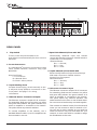
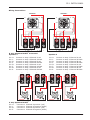
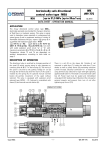
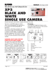
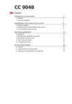
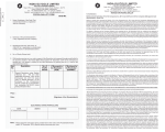
PP-1
PATCH
PANEL
USER MANUAL
CONTENTS
Specifications .................................................... 2
Important Information..................................... 3-4
Introduction
Unpacking
Mounting
Precautions
Operating Instructions...................................... 5-6
Front Panel
Rear Panel
Wiring Instructions.............................................. 7
Specifications
Power Supply....................................... AC 230V 50HZ
Protection........................................... MCB Rated at 32 Amps
Power Input Connector.......................... C32 Socket (provided)
Indicators........................................... Live, Neutral, Earth, Sequencer 1 to four
Power Output Connectors...................... Powercon - NAC3MPB©
Sequencer........................................... Push-on, Push-off switch.
Assignable Matrix................................. Inputs 8 x Pair Pomona Sockets
(Pomona Plugs Provided)
Output................................................ Outputs Speakons 4 x NL4MP
2 x NL8MP
Signal Connectors................................ Female XLR
Link Connectors................................... Male XLR
Ethernet Connection............................. RJ45
USB................................................... 2 x USB Sockets
Goose Neck Light................................. Goose Neck Light on USB Connector
Dimensions H x W x D (mm)................. 89 x 483 x 455
In Carton 140 x 570 x 610
Weight (Kgs)....................................... Net Weight 9
In Carton 10.8
As part of our continuous R & D programme
2
reserve the right to change specifications without prior notice
E&O.E.
PP-1 PATCH PANEL
USER MANUAL
PP-1 PATCH PANEL
The information contained within this manual does not include all of the details of design, production or
variations of the equipment. Nor does it cover every possible situation that may arise during installation,
operation or maintenance. If you need particular assistance beyond the scope of this manual please contact our
technical staff.
CAUTION
RISK OF ELECTRIC SHOCK
DO NOT OPEN
WARNING! RISK OF HAZARDOUS ENERGY!
TO REDUCE RISK OF ELECTRIC SHOCK OR FIRE DO NOT
EXPOSE TO RAIN OR MOISTURE.
NO USER SERVICEABLE PARTS INSIDE.
REFER SERVICING TO QUALIFIED SERVICE PERSONNEL.
UNIT MUST BE EARTHED AND CORRECTLY FUSED.
The lightning bolt triangle is used to alert
the user to the presence of un-insulated
“dangerous voltage” within the unit that
may constitute a risk of electric shock.
The exclamation mark triangle is used to
alert the user to important operating or
maintenance instructions in the
literature accompanying the product.
Features
CE Conformity
This equipment has been tested and found to conform
to the requirements of the EMC Directive 89/336/EEC,
the requirements of the Low Voltage Directive
73/23/EEC, amended by 93/68/EEC and to the
following standards:
EMC Emission
EN55103-1 (1996)
EMC Immunity EN55103-2 (1996)
Electrical Safety EN60065 (1998)
!
!
!
!
!
!
!
!
!
!
8 x Pairs of Inputs on Binding Post
2 x Outputs on 8 way Speakon Connector
4 x Outputs on 4 way Speakon Connector
Sequential Start
Trip Switch
4 x Network Connectors
Inputs and Links on XLR
2 x USB Sockets / USB Goose neck light
Power on C32 Sockets
Attractive styling
Wellington Close • Parkgate • Knutsford
Cheshire • WA16 8XL • England
Tel: +44 (0)1565 654641 • Fax: +44 (0)1565 755641
Email: [email protected] • Website: www.ohm.co.uk
3
Introduction
Congratulations on having purchased an OHM PP-1 Patch Panel
Please read this manual and familiarise yourself with the operation of your OHM PP-1 Patch Panel
before you attempt to power up this unit. For your own safety we recommend you take the time to
read all the warnings and precautions on the page opposite and study the connection details to
ensure correct usage and avoid any misuse which may invalidate your warranty.
Record the model and serial number, found on the back of the unit, in the spaces designated on the
warranty card and in the space provided below. Refer to the model and serial number whenever you
call upon your dealer for information or service on this product.
Model
Serial Number
Unpacking
Carefully open the shipping carton and check for any noticeable damage.
Every OHM PP-1 Patch Panel has been rigorously tested and inspected before being carefully
packaged, prior to shipping. If any damage has occurred to the packaging or the unit during transit,
please notify the delivery company as soon as possible. Only the consignee can file a claim against
the carrier for shipping damage. Be sure to save the carton and all packing materials for the carriers
inspection.
We recommend that you retain the original carton and packing materials for use should you transport
or ship the unit in future.
Mounting
Front and rear mountings are fitted to each unit, which conform to standard 19” rack strip
specifications. We recommend that you make use of these mountings and install your Patch Panel in
a suitable equipment rack, such as a UC-Series Flight case, also available from OHM. Please refer to
the specification table (page 2) for the correct height and depth information for your particular model
and ensure sufficient rack space is available.
Precautions
!
!
!
!
!
!
!
!
!
4
Retain this manual for future reference.
Do not stand the patch panel vertically on it’s rear.
Always check that the correctly rated power is supplied to your unit.
When connecting external units to this unit ensure that correctly wired connectors are used, refer
to the user manual for the external unit for this information.
Avoid direct contact of your unit with water or other liquids. Do not operate while standing in
liquid.
When cleaning the unit wipe with a soft, dry cloth. If more heavy duty cleaning is required
disconnect from the mains and use a damp cloth, ensuring that the unit is completely dry
before reconnecting to the mains.
Do not use solvents or chemicals on the exterior of the unit as they may cause the surface to
discolour and peel.
Do not use this unit with frayed or broken power cords.
If you experience continuous problems, disconnect from the mains and refer to a qualified
service engineer.
PP-1 PATCH PANEL
OPERATING INSTRUCTIONS
1
4
3
2
5 6 7
8
LIVE
USB LIGHT
RJ45
INPUT 1
LINK 1
LINK 2
INPUT 2
ASSIGNABLE
INTERNAL
MATRIX
SPEAKER 2
1
SPEAKER 1
EARTH
NEUTRAL
MAINS
230V~
50Hz
32A
PUSH
PUSH
SEQUENCER
POWER 4
POWER 3
1
9
10
11
12
2
13
3
4
POWER 2
POWER 1
15 14
FRONT PANEL
1 Backlit Logo (Blue)
Indicates that the Patch Panel is switched on.
Powered by maintenance free LED’s.
2 Ethernet Connector (RJ45)
Use a standard network cable to connect up to
four amplifiers to a single network.
Important: Use either the RJ45 on the front or
rear of Patch Panel. Do not connect to both as
they are wired together.
3 Outputs 8 way Neutrik© Speakon
Connectors
Accepts 8 way Neutrik© Speakon plug
connector NL8FC. Wired internally to the rear
Binding Posts.
4 USB Sockets
2 x USB sockets to take USB peripherals such
as LED Gooseneck Lights 1 x provided.
5 Earth Indicator LED (Green)
Indicates that the Earth has been correctly
wired. Will not light if wiring is incorrect.
6 Live Indicator LED (Red)
Indicates that the Live has been correctly
wired. Will not light if wiring is incorrect.
7 Neutral Indicator LED (Blue)
Indicates that the Neutral has been correctly
wired. Will not light if wiring is incorrect.
8 Mains Input Single Phase C32 Socket.
9 & 12 Inputs 1 & 2 on female XLR
Electronically balanced input sockets accept
XLR male connectors. Parallel wired to inputs
A/B on rear.
Wired as follows:
Pin 1 = Ground,
Pin 2 = Hot,
Pin 3 = Cold.
10 & 11 Input Links 1 & 2 on male XLR
Electronically balanced input link sockets
accept XLR female connectors. Parallel wired to
inputs links A/B on rear.
Wired as follows:
Pin 1 = Ground,
Pin 2 = Hot,
Pin 3 = Cold.
13 Output 4 way Neutrik© Speakon
Connectors
Accepts 4 way Neutrik© Speakon plug
connector NL4FC. Wired internally to the rear
Binding Posts.
14 Sequencer On/Off Button
This button enables the amps to be turned on
in sequence. After an interruption in mains
supply the sequencer will automatically
restart.
15 Sequencer Indicator LED’s (Red)
Lights up as to indicate the amplifiers have
powered up.
Accepts female C32 Plug (Provided). Ensure
correct wire thickness and configuration is
used.
5
5
4
1
ETHERNET ROUTER RJ45
PATCH PANEL
TRIP
SWITCH
ON
OFF
AMP 4
WELLINGTON CLOSE • PARKGATE • KNUTSFORD • CHESHIRE • WA16 8XL • Tel. +44 (0)1565 654641 • e-mail: [email protected] • www.ohm.co.uk
4
3
2
B
AMP 4
A
B
AMP 3
A
B
AMP 2
A
B
AMP 1
MAINS OUTLETS USE NEUTRIK POWERCON PLUG NAC3FPB MAXIMUM 20 AMP
AMP 2
AMP 1
B
AMP 4
A
B
AMP 3
A
B
AMP 2
A
B
AMP 1
INPUT
PUSH
PUSH
3
2
AMP 3
A
1
A
INPUT B
6
LINK B
LINK A
INPUT A
7
REAR PANEL
7 Input Links Channel A/B on male XLR
1 Trip Switch
To turn on the unit put the switch to on.
Unit will trip out automatically if a short circuit is
detected.
2 Power Connectors
©
4 x male Neutrik Powercon connectors to take
inline female Neutrik© Powercon Plug type
NAC3FCB.
Wired as follows:
L = Live: Brown
B = Neutral: Blue
E = Earth: Yellow /Green
3 Inputs Binding Posts
Accepts Pomona plug, wired internally to the
4 way and 8 way Speakon connectors on the
front panel. See page 7 for wiring
information.
4 Ethernet Router Connectors Outputs
The Ethernet connector accepts RJ-45 connector
for networking. Built into the connector is a yellow
and green LED indicator. the green indicator is lit
when an amplifier is connected to the network.
The yellow shows any network activities.
To connect amplifiers to the network, use a
standard Ethernet cable. Up to four amplifiers can
be connected to one unit.
6
Electronically balanced input link sockets
accept XLR female connectors. Parallel wired to
inputs links ½ on front panel.
Wired as follows:
Pin 1 = Ground,
Pin 2 = Hot,
Pin 3 = Cold.
6 Inputs Channel A/B on female XLR
Electronically balanced input sockets accept
XLR male connectors. Parallel wired to
inputs1/2 on front panel.
Wired as follows:
Pin 1 = Ground,
Pin 2 = Hot,
Pin 3 = Cold.
5 Ethernet Connector input
The Ethernet connector accepts RJ-45 connector
for networking. Built into the connector is a yellow
and green LED indicator. the green indicator is lit
when an amplifier is connected to the network.
The yellow shows any network activities. Use
either the RJ45 on the front or rear of Patch Panel.
Do not connect to both as they are wired together.
This connects to external router, from the external
router you can connect to either a network or PC.
You can use as many switches as you need but
make sure there is only one router built into your
network. A router with DCHP is needed to assign
the IP addresses to the units.
PP-1 PATCH PANEL
Wiring Instructions
SPEAKER 1
SPEAKER 2
1+
1-
2+
2-
SPEAKER 1
3+
1+
4-
1-
4+
2+
3-
2-
4-
4+
3-
SPEAKER 1
3+
4+
3+
2+
1+
4+
3+
2+
1+
4-
3-
2-
1-
4-
3-
2-
1-
B
AMP 4
A
B
AMP 3
B
A
AMP 2
A
B
A
AMP 1
©
8 way Speakon NL8FC Connector
Speaker 1
Pin
Pin
Pin
Pin
Pin
Pin
Pin
Pin
1+
12+
23+
34+
4-
Connect
Connect
Connect
Connect
Connect
Connect
Connect
Connect
to
to
to
to
to
to
to
to
amp
amp
amp
amp
amp
amp
amp
amp
2+
2- B
4
4
4
4
3
3
3
3
Channel
Channel
Channel
Channel
Channel
Channel
Channel
Channel
1+
AMP 4
A
A
B
B
A
A
B
B
4
red
black
red
black
red
black
red
black
2+
A 1-
2- B
1+
1-
Speaker 2
Pin
Pin
Pin
Pin
Pin
Pin
Pin
Pin
1+
AMP 3
1+
12+
23+
34+
42+
A 1-
2- B
1+
2-
1-
4 way Speakon NL4FC©
Connect to Channel
Pin 1+
Connect to Channel
Pin 1Connect to Channel
Pin 2+
Connect to Channel
Pin 2-
A
A
B
B
to
to
to
to
to
to
to
to
amp
amp
amp
amp
amp
amp
amp
amp
1+
AMP 2
2+
1-
A 1-
2+
Channel
Channel
Channel
Channel
Channel
Channel
Channel
Channel
2- B
A
A
B
B
A
A
B
B
red
black
red
black
red
black
red
black
1+
AMP 1
A 1-
1+
2-
2
2
2
2
2
1
1
1
1
2+
1+
2-
3
2+
Connect
Connect
Connect
Connect
Connect
Connect
Connect
Connect
1-
2-
1
2+
positive (red)
negative (black)
positive (red)
negative (black)
7
OHM UK HEAD OFFICE
OHM EUROPE
OHM CHINA
OHM (UK) Limited
Wellington Close
Parkgate Industrial Estate
Knutsford
Cheshire
WA16 8XL
England
Danzer & Kamm Gbr
Schnieglinger Str. 166
D-90425 Nuremberg
Germany
Guangzhou OHM Audio Co., Limited
#3-1 Huancun Road
Caibian Village, Donghaun Road
Shiqiao, Panyu, Guangzhou
P.R. China
Tel: +44 (0) 1565 654641
Fax: +44 (0) 1565 755641
e-mail: [email protected]
www.ohm.co.uk
OHM ASIA
Harness Overseas (P) Limited
SCO 381
Sector 37D
Chandigarh
India
Tel: +91 172 2697 465
Fax: +91 172 2688 254
e-mail: [email protected]
www.harnessasia.com
Tel: +49 (0) 911 230 85 10
Fax: +49 (0) 911 230 85 33
e-mail: [email protected]
www.ohm-europe.com
OHM POLAND
OHM Polska Sp.z.o.o
62-300 Wrzesnia
Ul. Wojska Polskiego 13
Poland
Tel: +48 603 984 136
Fax: +48 61 640 02 62
e-mail: [email protected]
www.ohm.pl
Tel: + 86 20 3451 1231
Fax: + 86 20 8466 2675
e-mail: [email protected]
www.ohmchina.com