1
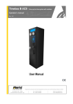
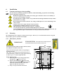
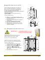
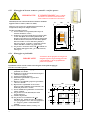
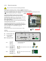
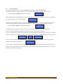
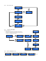
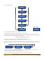
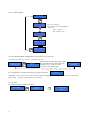
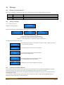
Hydro Jet Terminal for H.P. Wash-Bay Plants
Operator’s manual
Rev. 1.03
HYDRO JET S
in-wall mount
HYDRO JET S
wall mount
HYDRO JET S
(with display)
HYDRO JET
User Manual
HYDRO JET ALBERICI
Rev. 1.03
Manual
Pagina 1
NOTICE
This manual has been prepared with the utmost care. Nevertheless, it is not
possible to assure at any time the exact correspondence of the descriptiosn to the product features.
Alberici SpA shall not be held liable by the User for any damage, losses, or third party claims
arising from any uses of the manual or of the product .
2
TABLE OF CONTENTS
1.
Package content............................................................................................................................ 5
2.
Product description ...................................................................................................................... 5
3.
Reception and Handling ............................................................................................................... 7
4.
Parts Denomination ...................................................................................................................... 8
5.
Dimensions................................................................................................................................... 9
6.
Installation .................................................................................................................................. 10
7.
Switch-on ................................................................................................................................... 15
8.
Operation .................................................................................................................................... 16
9.
Configuration ............................................................................................................................. 19
10. Messages .................................................................................................................................... 27
11. Maintenance and Cleaning ......................................................................................................... 28
12. Disposal of the product .............................................................................................................. 28
13. Terms of Guarantee ................................................................................................................... 28
14. Customer Service ....................................................................................................................... 28
Revisione n°
Data
1.00
1.01
1.02
03.08.12
12.10.12
07.03.13
1.03
22.07.15
HYDRO JET ALBERICI
Rev. 1.03
STORICO REVISIONI
Modifica
Creazione
Hopper S11 invece di HopperOne
8° Programma, Scheda Servo,
Comando combinatorio relays
Nuovo frontespizio
Note
Scheda Servo solo opzionale
Manual
Pagina 3
4
Dear Customer,
we would like to thank you and congratulate for your choice. We trust that you will appreciate the
quality and performance of our HYDRO JET control station.
This machine operates by cctalk protocol, the well-established serial communication mode that
provides security and precision.
Please pay careful attention to the information highlighted by the following signs:
IMPORTANT NOTICE REGARDING THE OPERATOR’S SAFETY AND THE PROPER FUNCTIONING
OF THE EQUIPMENT.
IMPORTANT NOTICE REGARDING DANGERS AND RISKS DUE TO ELECTRICITY.
IMPORTANT NOTICE REGARDING DANGERS AND RISKS DUE TO HIGH GEMPERATURES.
GENERAL INFORMATION.
Please read carefully this handbook, to obtain the most from your HYDROJET Station
1.
Package content
The package contains:
1. The Alberici HYDRO JET Control Station for H.P. Wash-Bay Plants
2. One pair of safety keys
3. User manual (this manual)
4. Possible options (cfr. page 8)
This product has been packed with the utmost care. If you receive it damaged or incomplete, please
notify immediately your findings to the Carrier, and collect it only under conditional signature.
The packing material, wooden pallets included, must be disposed off according to your Country
laws and regulations. The product itself, once dismissed, must be disposed off according to the
same laws and regulations.
2.
Product description
2.1
Intended use
The HYDRO JET equipment allows payment for and activation of 8 self-service washing programs. It is ideal for high
pressure Wash-Bay plants. It is designed for outdoor installation and functioning, without direct exposure to weather
conditions. It is recommended that it is sheltered from both rain/hail and sun rays.
It is available with floor-stand, for wall-mount, and for in-wall embedding.
This equipment has been certified IP54. However, it is always advisable to install it in a position conveniently
protected against bad weather and strong light.
HYDRO JET ALBERICI
Rev. 1.03
Manual
Pagina 5
2.2
Available functions
- Activation of one or more among the 8 programs provided.
- Accounts control on display (only through buttons on the board, or by remote keypad)
- Free custom-configuration (only through buttons on the board, or by remote keypad)
- Interactive User Menu; the User can switch to his preferred language among 5 available
2.3
General Data
Classification:
Protection degree:
Overall dimensions:
Weight (options not considered):
Power supply:
Nominal power:
Peak power:
Operating temperature:
Operating humidity conditions:
Installation:
System components:
Power supply box
Control board
Scheda Relé di interfaccia
Display
Coin acceptor
RFID keys cashless reader
Class I equipment ( CEI EN 60335-1), Category IV (CEI EN 55014-2)
IP 54 min. (EN 60529)
400 mm (l) x 755 mm (h - 1630 with floor-stand) x 270 mm (p)
30 Kg (wall-mount) - 48 Kg (with floor-stand)
24 Vac - 50 Hz
12 W (0,5 A)
20 W (0,8 A)
-10°C ÷ +50°C
- 10% ÷ 90% non-condensed
Wall-mount, or embedded into wall (blind niche or open cut-out), or on floorstand.
Power switching 280 W con filtro antidisturbi, e ventilato
Alberici HYDRO JET ccTalk v. 1.02
Alberici 8PR, corrente ai contatti dei relé 3 A nominali
LCD blu 2 x 16
Only in HYDRO JET S: 8 blue LCD functional displays 2 x 16, one for each
program button
AL66SC waterproof
Alberici ACS Mifare®
Default currency is the Euro. Please ask in advance for different needs.
2.4
Reference Norms
Development, design and production have been made according to the following EU regulations:
1998/37/CE
On equipments
2004/108/CE (ex 89/336/CEE)
EM compatibility
2006/95/CE (ex 73/23/CEE)
Low voltage equipments
CEI EN 60335
Safety of Electrical equipment
CEI EN 60529
IP Protection
2.5
Warning
- Comply with the instructions in this manual
- Switch power off before any maintenance operation
- Use only within the recommended temperature/humidity range
- Do not expose the machine to direct sun light or to incandescent light (> 3000 Lux)
- Do not use the machine when the ambient temperature and humidity are not within the
recommended Operational range
- When in presence of car exhaust gas or smoke, clean and check the components regularly and frequently.
- Do not favour contact with dusts or chemical moisture or sprays, water or other liquids
- Instal indoor
- Wipe clean by a dry piece of cloth (or slightly wet with alcohol)
- Do not use thinners or organic solvents
- Attenersi alle istruzioni del presente manuale.
6
3.
Reception and Handling
Dopo il collaudo, l’apparecchio e i suoi accessori vengono accuratamente imballati e chiusi in involucri di cartone.
Le scatole in cartone vengono poi poggiate su un bancale in legno, per ridurre al minimo i rischi di urti e colpi durante
le operazioni di carico, trasporto, trasbordo, e scarico.
3.1
Ricevimento
Al ricevimento, impiegare un carrello elevatore o un transpallet manuale per spostare i colli.
Prima di firmare il documento di ritiro, aprire l’imballo e verificare se il prodotto è stato danneggiato nel trasporto, o se
presenta altre anomalie. In tal caso segnalatelo immediatamente allo spedizioniere, facendogli trascrivere il reclamo sul
documento di ricezione, prima di apporvi la vostra firma.
Nel caso sia necessario stivare l’apparecchio prima dell’installazione, abbiate cura di conservarlo all’interno del suo
imballo, in un ambiente chiuso e comunque al riparo dagli agenti atmosferici.
3.2
Apertura dell’imballo
E’ consigliabile sballare la macchina presso il luogo in cui deve essere installata.
Tagliare le reggette di contenimento (attenzione all’ ”effetto frusta”), se presenti, e quindi togliere i nylon e le pellicole
protettive.
Estrarre i punti di graffatura, e aprire la scatola di cartone. L’apparecchio è bloccato, all’interno dell’involucro, da
distanziali posizionati su ciascuno spigolo; c’è quindi un’intercapedine di ca. 5 cm fra le lamiere e l’imballo. Fare
comunque attenzione a non graffiare le superfici della macchina con gli eventuali arnesi utilizzati.
Estrarre il prodotto con attenzione, e posizionarlo in verticale.
Tutto il materiale d’imballo, incluso il bancale in legno, deve essere riciclato o smaltito in conformità alle leggi vigenti.
HYDRO JET ALBERICI
Rev. 1.03
Manual
Pagina 7
4.
Parts Denomination
OPTIONS
EXTERNAL VIEW
Main
Display
Cashless RFID
reader for keys
Program 1
pushbutton
Safety lock
Programs 2-8
pushbutton
and (only in
HYDROJET ‘S’)
functional
displays
AA-0123
Frame for
in-wall
embedding
(blind niche)
AA-0120
Floor-stand
Hydro Jet
AA-0124
Frame for
through-wall
mount
(open cut-out)
Coin / token entry
Coin/token return
AA-0122
Wall-housing
for cables
Hydro Jet
AA-0121
Frame for
wall-mount
INSIDE VIEW
C
POS. PART REF.
E
A
F
A
SH-1I21-000T
Hydro Jet pcb, wet-proof
B
S-020901-120
8PR HJ board, wet-proof
C
C-0701013-000
Safety lock
D
GE-66SC-000T
AL66S ccTalk, modifiable
E
CH-BC00
ACS RFID cashless reader
F
PL-MD0T-000H
8 x Vandal-proof pushbuttons,
RGB 12V
G
SH-3031-000T
Functional Display DSOne blue
with wet-proof pcb
(ONLY ‘S’ TYPE)
H
INTER-001
Main switch, 4 A
I
SH-40AN
Servo board 12Vdc (please see
page 14 for wiring) for coin signal
B
I
D
8
H
DESCRIPTION
G
5.
Dimensions
Wall-mount:
On floor-stand:
270
690
750
270
1630
325
400
240
In-wall or Through-wall mount:
615
690
880
70
240
400
325
400
All measures in mm.
HYDRO JET ALBERICI
Rev. 1.03
Manual
Pagina 9
6.
Installation
6.1
Cautions and dangers when installing
The unit must be installed by qualified technicians, skilled in handling, preparation and mounting,
electric connections, and start-up.
Handle the equipment safely. Make use of safety gloves and shoes. Take care of stability, to
prevent any risk of danger to people.
Even though power supply is 24Vac, keep it disconnected during installation and any further
maintenance or servicing.
Do not modify the circuits in the unit. Any change could impair the correct functioning of the
safety circuits.
The power line must comply with the Norm CEI 64-8/7.
In particolare il conduttore di messa a terra deve essere
inderogabilmente conforme alle prescrizioni, e comunque
avere sezione non inferiore ai limiti stabiliti dalla norma CEI 64-8/4.
Si raccomanda di porre la linea sotto la protezione di un interruttore differenziale da 10A , per
poter agevolmente togliere l’alimentazione caso di operazioni di manutenzione.
6.2
Mounting
The equipment has been certified as IP54 protection degree. However, it is recommended to instal it away from
direct weather agents as rain/hail and sunlight..
6.2.1 Wall-mount fixation:
IMPORTANT!
IT IS ESSENTIAL
THAT THE WALL IS SOLID ENOUGH
TO SUPPORT THE HANGING WEIGHT OF THE UNIT.
400
30 35 60
30 45
Prepare the wall outlet of the cables corresponding to
the frame slant side.
If the cables can be brough only form underneath, it is
recommended that you make use of the optional housing
for cables (ref. nr. AA-0122, height 830 mm).
X
75
X
Y
X
X
X
455
X
Y
95
100
Y
40
Φ34
35
140
170
450
280
Y
750
Tale the following steps:
1) Fasten the frame to the wall by fischer-bolts,
through the 6 x Φ 10 mm bores (X).
2) Slip the cables through the Φ 34 hole in the
frame, then through the Φ 22 bush in the unit.
Fasten the cabinet to the 4 (Y) studs, and
tighten the M8 nuts and washers.
3) See § 6.2.2.1 for electrical connections.
250
70
The dedicated frame (codice AA-0121) must be used to
fix the Hydro Jet cabinet to the wall.
55
10
230
55
Montaggio della colonna copri-cavi AA-0122:
330
H
350
830
La colonna è alta 830 mm, quindi è bene che la
macchina sia fissata al muro in modo che il suo profilo inferiore
collimi a filo di tale altezza.
E’ quindi consigliabile montare prima la colonna e in
seguito la macchina.
x
350
55
Quando i cablaggi dell’alimentazione per la Hydro Jet
appesa a parete provengono dal basso, si può utilizzare
questo accessorio per nascondere i cablaggi alla vista.
x
z
x
z
z
x
75
Procedere nel modo seguente:
z
x
1) Svitare le 5 + 5 viti laterali Z, ed estrarre il carter.
2) Posizionare il telaio, e segnare le posizioni dei sei punti
di fissaggio X a parete.
3) Forare in corrispondenza dei punti X e predisporre i
tasselli nei fori.
4) Fissare la colonna al muro attraverso i fori X.
5) Far risalire i cablaggi attraverso il foro H.
6) Rimettere il carter, e fermarlo con le 5 + 5 viti Z.
7) Prima di montare il telaio della macchina al muro,
introdurvi il cablaggio.
160
70
x z
265
405
135
70
405
350
=
=
95 40
15
105
15
200
6.2.2 Montaggio ad incasso su muro con foro cieco:
E’ INDISPENSABILE
CHE LA PARETE
SIA SOLIDA A SUFFICIENZA PER SOSTENERE
SENZA PERICOLO IL PESO DELLA MACCHINA
Il mobile Hydro Jet si monta all’interno del muro
mediante l’apposito telaio (codice AA-0123).
400
30 45
X
X
Y
250
620
455
X
X
Y
Y
X
Φ34 X
X
240
95
95
X
35
690
250
Y
50
HYDRO JET ALBERICI
Rev. 1.03
75
70
95
Predisporre l’uscita del cavo di alimentazione dalla
parete in corrispondenza della parte obliqua del telaio.
Procedere nel modo seguente:
1) fissare il telaio al muro con robusti tasselli a
espansione, attraverso i fori X di Φ 10 mm
2) far passare i cavi dentro il foro Φ 34 del telaio e
poi nella boccola Φ 22 dell’apparecchio;
quindi, ancorare quest’ultimo alle 4 viti
prigioniere Y, e stringere a fondo i relativi dadi
M8 e rondelle.
3) Per l’allacciamento, vedere § 6.2.2.1.
250
35
Il foro deve avere le seguenti dimensioni:
40
IMPORTANTE!
50
Manual
Pagina 11
6.2.3 Montaggio ad incasso su muro o pannello con foro aperto:
E’ INDISPENSABILE
CHE LA PARETE
SIA SOLIDA A SUFFICIENZA PER SOSTENERE
SENZA PERICOLO IL PESO DELLA MACCHINA
Il mobile Hydro Jet si monta all’interno del muro mediante
l’apposito telaio a cornice (codice AA-0124).
75
250
75
95
Predisporre l’arrivo del cavo di alimentazione dal basso, in
corrispondenza della parte obliqua del telaio.
250
250
Procedere nel modo seguente:
1) Forare il muro in corrispondenza dei 10 fori X
esistenti sul telaio a cornice.
2) Predisporre in ogni foro della faccia posteriore della
cornice dell’Hydro Jet una barra filettata M8, di
lunghezza pari allo spessore della parete, maggiorata
di almeno 20 mm. Posizionare la macchina, infilare
dal retro il telaio a cornice sulle barre filettate, e
bloccare l’insieme “a panino”, stringendo a fondo i
relativi dadi M8 e rondelle (cfr. figura sotto).
3) Far passare i cavi dentro la boccola Φ 26 situata sul
lato obliquo dell’apparecchio; per l’allacciamento,
vedere § 5.3.
TELAIO A CORNICE
(interno muro)
CORNICE FRONTALE
MACCHINA (esterno)
95
IMPORTANTE!
6.2.4 Montaggio su piedistallo:
IMPORTANTE!
Assicurarsi che la superficie di sostegno sia
adeguata a portare il peso dell’apparecchio
e del piedistallo, e che sia perfettamente
piana ed orizzontale.
Il piedistallo si fissa al suolo tramite i fori integrati nel suo piede d’appoggio
Procedere nel modo seguente:
12
400
100
100
75 25
90
110
A
110
180
110
240
90
30
25 75
30
1) Verificare che il piano di appoggio del
piedistallo sia a livello.
2) Predisporre l’uscita dei cavi all’interno del foro
180x110 (A in figura).
3) Togliere il pannello anteriore.
4) Posizionare il piedistallo e segnare dove
praticare i fori Z.
5) Rimuovere il piedistallo, perforare il pavimento
e inserire i tasselli.
6) Riposizionare il piedistallo. Se necessario
interporre delle rondelle di spessoramento o dei
distanziali fra la base e il suolo.
7) Fissare saldamente il piedistallo con dadi M8 e
relative rondelle.
8) Far passare il cavo di alimentazione nella
nicchia superiore.
9) Chiudere il pannello.
10) Far passare il cavo nella boccola Φ 22
dell’Hydro Jet, quindi ancorare quest’ultimo,
come già spiegato in 6.2.1, alle 4 viti prigioniere
Y, e stringere a fondo i relativi dadi M8 e
rondelle.
11) Per l’allacciamento elettrico, vedere § 5.3.
6.2.2.1
Electrical connections
The power line must be disconected during installation.
Voltage supply is required to be 24 Vac. Always use a Φ 4 mm Ground wire.
Please notice: the equipotential electronic Ground must not be connected to the Earth.
It is advised to shield the cables to the wash-bay, to prevent possible interferences from the power wires.
Power capacity of each relay is 3 A nominal.
~ 24 V
LAYING THE CABLES: slip all the cables in the machine,
through the bush located in the machine bottom slant side.
POWER SUPPLY CABLE 24 Vac: connect the 24 Vac cable to the
upper clamps of the Master switch (see picture aside).
Power will go through to the 8PR board (J20 socket) only when the
master toggle is pulled up.
Two 4A fuses protect the unit. They are located under the black clips
at the right side of the main switch.
ACTIVATION LINES (from RL 1 to 8): activation cables to the
Wash-Bay equipments can be connected directly to the relays output
connectors of the 8PR board, or bridging them through the light
brown screw-clamps in a row underneath (see page 15).
GROUND CABLE:
The ground cable must be connected to the yellow-green clamp.
GND
BOARDS:
All the cables connecting the boards between each other are already connected.
P
P
R
O
G
PR
RO
OG
G
OK
+/-
= confirm selected value
= menu navigation;
modify values
S
S
T
P
ST
TP
P
P
P
T
PT
T
+
+
T
T
S
T
TS
ST
T
REG = display light trimmer
P
P
4
/
7
R
G
B
3
R
G
B
2
R
G
B
1
P4
4/
/7
7R
RG
GB
B3
3R
RG
GB
B2
2R
RG
GB
B1
1 S
S
P
SP
PIII
CC12
Pin 1. DATA
Pin 2. GND
Pin 3. NC
Pin 4. +12 V
Pin 4. +24 V
RGB 1, 2
Pin 1. MICRO N.O.
Pin 2. LED R (red)
Pin 3. +12V
Pin 4. LED B (blue)
Pin 5. GND
Pin 6. LED G (green)
RGB 3
Pin 1. MICRO N.O.
Pin 2. LED R (red)
Pin 3. +12V
Pin 4. LED B (blue)
Pin 5. GND
Pin 6. LED G (green)
HYDRO JET ALBERICI
Rev. 1.03
C
C
C
1
2
CC
C1
12
2
--
O
O
K
OK
K
C
C
C
T
CC
CT
T
2
2
4
24
4
P
P
W
R
PW
WR
R
O
O
U
T
OU
UT
T
P
P
W
R
PW
WR
R
IIIN
N
N
2
2
4
1
2
G
N
D
24
41
12
2G
GN
ND
D
R
R
E
G
RE
EG
G
[AL66 COIN ACCEPTOR]
[and to 8PR board]
[RGB LUMINESCENT PUSHBUTTONS]
[SERVO PRE-SWITCHING BOARD]
Manual
Pagina 13
PRE-SWITCHING BOARD (OPTION):
If your system requires to receive a pre-switching signal when one coin / token has been accepted, connect the
output of the “Servo” pre-switching board to the washing system central box, according to the diagram below.
To reach the 8PR board, remove the two Phillips screws that keep the protection plexy.
J3 = +12Vdc IN
(from P3 socket in
main control board)
Pre-switching
signal to the
central box of
the washing
system (coin
accepted)
+
+12Vdc
CONNECTION TO THE WASH-BAY EQUIPMENTS:
The wirings to the Wash-Bay system must be connected to the relays on the 8PR interface board (rear wall of the
Hydro jet unit): connect one relay for each available program (No. 01 – No. 08) and the common GND wire (COM).
Power capacity of each relay is 3 A nominal.
To reach the 8PR board, remove the two Phillips screws that hold the protection plexy.
COM = COMMON for N.O.
(normally open) Outputs
relays 1-8
14
Gnd 1 = COMMON (-) Gnd 2 = COMMON (-)
for inputs IN1, IN2,
for inputs IN6, IN7,
IN3, IN4, IN5
IN8
Output clamps (N.O. Relays)
Output
Description
Output
Description
NO1
Normally open contact Relay 1
NO5
Normally open contact Relay 5
NO2
Normally open contact Relay 2
NO6
Normally open contact Relay 6
NO3
Normally open contact Relay 3
NO7
Normally open contact Relay 7
NO4
Normally open contact Relay 4
NO8
Normally open contact Relay 8
The relays can be used for direct activation (1 program = 1 relay), or for combined activation (1 program =
more relays). The combinations can be set by the Menu: see section 9.3.5.1 Programs setup.
All the relays share the same COMMON end (COM): take
care that your wirings respect such condition!
WASH-BAYS WITH FEEDBACK SIGNAL:
Some types of Wash-Bays are able to transmit information about their operational status (i.e. ‘out of service’, ‘in operation’, ‘in stand-by’, ‘foam
missing’ a.s.o.) to the self-service activation station. This is made by a 24V or 0V signal sent to the preset input contacts of the interface board. In
such cases, the Hydro Jet can be made to react accordingly: i.e., it can disable payment acceptance if the Wash-Bay plant is out of service.
If your Wash-Bay plant is capable to provide such feed-back, and you want to make use of it,please check in advance with the Alberici pre-sales
Service whether the Hydro Jet supports the type of operation that you require. If your request complies with the implemented possibilities, it will be
enough to set the Dip-Switches 3-4-5-6 (located on the 8PR interface board) according to the feedback type, as per chart below.
7.
DS3
DS4
DS5
DS6
Type of feedback given by
the Wash-Bay plant
OFF
OFF
ON
ON
X
ON
OFF
ON
ON
Y
OFF
ON
ON
ON
W
ON
ON
ON
ON
Z
Switch-on
Turn on the equipment by pulling up the lever of the safety main switch: the ON sign will show up white on red
background.
The unit will check the status of the components in the circuit. When the check ends, the display will show the stand-by
message, that can be changed according to the Owner’s wish (see sect. PROMO, in 9.3.9 Menu Functions):
HYDRO JET
shifting with:
Promo
11:28
12/12/12
Service Price 1.00 €
The pushbuttons will lit up in blue colour. The unit is ready for operation.
HYDRO JET ALBERICI
Rev. 1.03
Manual
Pagina 15
8.
Operation
Never operate the unit when the door is open!!!
The unit works with coins and/or tokens, or with the RFID loyalty-key pre-loaded with credits. Pre-loading can be done
by the Manager, or at a self-service charging station (DRY CHANGE), or on the unit itself (see sect. 8.2 a).
Only one common price can be set for any of the 8 programs. Common price and 8 individual times must be set as per
instructions in 9.3.5.1 Programs setup.
Please note! IT IS NECESSARY TO SETUP THE NEEDED PROGRAMS: IF A PROGRAM HAS NOT BEEN
SET, THE PERTINENT PUSBUTTON WILL NOT LIT UP AND WILL NOT OPERATE. Set the common price for
all washing programs, as well as the individual timings for each of the 8 washing programs.
When in stand-by, the pushbuttons of the programs lit up in blue colour. The Stop/Language pushbutton lits in green.
Only in HYDRO JET S: each program pushbutton in Hydro Jet S is matched to its individual display. It is necessary to
set the writings (‘labels’) of each of the latter, in order to enable the program pushbutton to its function. To set the
writings, see 9.3.5.2 Set up label texts.
8.1
Activation by coin acceptor
Insert as much money as the service price shown on the main display.
If the Hydro Jet is equipped with the pre-switching board option, the first accepted coin will start the relay of the
“Servo” board (pulse length = 500 ms), so as to preset the washing system to receive the Program activation. Then the
User will push any of the 8 pushbuttons, switching the relay(s) relevant to the corresponing line(s).
In case the pre-switching board option is not included, program lines will be activated without prior warning according
to which one(s) the User will press, provided enough money has been introduced.
Therefore, if the inserted amount is sufficient, the following message appears:
Credit
1,00€
Select…
Credit
1,00€
…your program
At the same time, the 8 program buttons lit up in green colour, while the Language choice button lits up in red.
Press the button of your choice (say, No. 3), that will start flashing in yellow colour. The unit will activate the relay No.
3 or the preset one(s), as per section 9.3.5.1 Programs setup. The relay(s) shall remain activated according to the
peculiar programmed time (again see 9.3.5.1 Programs setup). The display shall show the count-down.
While any program is in progress, it is possible to start any different one: the first one will stop, and the second one
shall last in proportion to the time remained.
For instance, let us suppose that Program 1 is 120 sec., and Program 2 lasts 30 seconds. If Program 1 gets activated, and
after 60 seconds Program 2 is started , the second one will begin its countdown from 15 seconds.
It is advised that the price of the service is always set equal to the lower denomination accepted: i.e. if 0.50 €, 1.00 €
and 2.00 € are set to be accepted, price for the service is best set to 0.50 €.
However, the Operator might want to set the price to 1.00 €. In this case, see “Insufficient credit” below.
Insufficient credit: this condition may occur if the system must accept denominations such as 0.50 €, 1.00 € and 2.00 €,
and the price has been set to 1.00 € or 2.00 €.
Insert credit
Let us suppose price is set to 1.00, and the User
inserts 0.50 €. The message here beside will appear:
Even though the pre-switching option is included and operating (so that the coin signal has been sent to the washing
system), the program pushbuttons will not lit up ready, until another 0.50 € are dropped in so as to top up the 1.00 €.
Excess credit: this condition may occur if the system must accept denominations such as 0.50 €, 1.00 € and 2.00 €, and
the price has been set to 0.50 € or 1.00 €.
The unit cannot return any backchange, so it will automatically multiply the time preset for the chosen program by 2
(price= 0.50€, inserted 1.00€; or price=1.00, inserted 2.00€), or by 4 (price= 0.50€, inserted 2.00€) .
16
8.2
Uso con Chiavetta
La HYDRO JET include di serie il sistema Cashless di lettura RFID per chiavette fedeltà ACS:
Inserendo la chiavetta, il display visualizza lo stato del credito disponibile. Sono possibili i due casi a) e b):
a) Se il credito è insufficiente, compare il messaggio:
Inserire credito
Inserire monete fino al raggiungimento del valore che si desidera caricare sulla chiavetta, e premere il tasto illuminato
in verde. Attendere che scompaia il messaggio:
Salvataggio in corso
A questo punto, si illuminano di colore verde i tasti dei programmi attivabili con il credito ora disponibile. Estrarre la
chiavetta, oppure premere il tasto del programma desiderato, e seguire le istruzioni che compaiono sul display.
b) Se il credito è sufficiente, compare il messaggio:
Tasto verde per
caricare credito
e simultaneamente si illuminano di colore verde i tasti dei programmi attivabili con il credito disponibile.
Premere il tasto del programma desiderato, e seguire le istruzioni che compaiono sul display.
Se invece si desidera caricare la chiavetta nonostante si possieda sufficiente credito per attivare un servizio, introdurre
monete per l’importo che si desidera aggiungere al credito. Quindi, inserire la chiavetta. Il display invita alla scelta fra:
Selezionare
il programma
oppure
Tasto verde per
caricare credito
Premere il tasto “Cambio-lingua” (illuminato di verde, vicino alle bandierine) per trasferire credito sulla chiavetta.
Attendere che scompaia il messaggio:
Salvataggio in corso
A questo punto, si illuminano di colore verde i tasti dei programmi attivabili con il credito ora disponibile. Estrarre la
chiavetta se si intendeva soltanto caricarla con credito, oppure premere il tasto del programma desiderato, e seguire le
istruzioni che compaiono sul display.
HYDRO JET ALBERICI
Rev. 1.03
Manual
Pagina 17
8.2.1 Management key (Master Key, and Service Key)
By introducing the Master Key or the Service Key, it is possible to get to the unit Service Menu.
By the Service menu, it is possible to 1) initialize the User Keys, and 2) check the Account Records. The Service Key
allows to cancel the partial Accounts, the Master Key can cancel also the total amounts in the Account Records.
Insert Service
Key
Press
Green Pushbutton
INITIALIZATION
KEYS
ACCOUNT
RECORDS
4 secondi
Coins IN
0,00 €
4 secondi
Insert
key
Insert
User empty key
Coins OUT
0,00 €
DO NOT REMOVE
THE KEY…..
Wait……
(*)
Cashless IN
0,00 €
NOTICE:
ADDITIONALLY, WHEN INSERTING THE
MASTER KEY (BLACK) IT IS POSSIBLE TO
ACTIVATE ANY SERVICE FREE OF CHARGE.
THIS IS NOT POSSIBLE WITH THE SERVICE
KEY (WHITE OR YELLOW).
KEY
INIZIALIZED!
Remove
initialized key
Insert
key
Cashless OUT
0,00 €
Insert a new empty
key, or
(after 10 seconds):
Program
1
0,00 €
Uscita
automatica
Program
6
0,00 €
Residual Credit
Paid:
0,00 €
Cancel
Partials
Confirm
cancellation?
4 seconds
Remove
Service/Master Key
All Partials
cancelled
Automatic
Exit
Automatic
Exit
18
(*) If the key is
damaged, the
display will show:
‘DISABLED KEY’
9.
Configuration
The HYDRO JET is delivered with the following default configuration:
Board Parameters
AL66S [ccTalk] acceptor parameters
Programs time set-up
Service Price
€ 0.50 - …. - € 2.00
None
=1€
= ENABLED
If any variation is made, it will be possible to restore the default configuration as follows:
enter the initial menu, scroll by UP and DOWN keys and choose RESTORE DEFAULT CONFIGURATION,
then press OK: the message DEFAULT CONFIG. RESTORED will be displayed.
NOTICE: the RESTORE DEFAULT CONFIGURATION command resets the default PIN code (0000)
9.3 Menu Functions
9.3.1
SURF THE MENU
To enter the menu and navigate it, make use of the 3 keys located behind the board display.
P
P
R
O
G
PR
RO
OG
G
OK
+/-
= confirm selected value
= menu navigation;
modify values
S
S
T
P
ST
TP
P
P
P
T
PT
T
+
+
T
T
S
T
TS
ST
T
REG = display light trimmer
P
P
4
/
7
R
G
B
3
R
G
B
2
R
G
B
1
P4
4/
/7
7R
RG
GB
B3
3R
RG
GB
B2
2R
RG
GB
B1
1 S
S
P
SP
PIII
C
C
C
1
2
CC
C1
12
2
--
O
O
K
OK
K
C
C
C
T
CC
CT
T
2
2
4
24
4
P
P
W
R
PW
WR
R
O
O
U
T
OU
UT
T
P
P
W
R
PW
WR
R
IIIN
N
N
2
2
4
1
2
G
N
D
24
41
12
2G
GN
ND
D
R
R
E
G
RE
EG
G
NOTE: to enter some menus, the PIN code will be requested.
HYDRO JET ALBERICI
Rev. 1.03
Manual
Pagina 19
9.3.2
MENU STRUCTURE
HYDRO JET
Promo
EXIT
MENU
ACCOUNT RECORDS
DISPLAY
PERIFER. CCTALK
SET UP
EXIT
MENU
9.3.3
ACCOUNT RECORDS
This menu allows to:
- Check partials and totals, both cashed in and paid out;
- cancel the recorded total amounts (PIN code necessary);
- cancel the recorded partial amounts.
ACCOUNT
RECORDS
(*)
Cancel
Partials
Exit
DISPLAY
ACCOUNTS
Cancel
Totals
(*)PIN requested
Residual Credit
Paid:
0,00 €
Wash Prog.
7
0,00 €
Totals IN
0,00 €
Coins IN
0,00 €
Wash Prog.
9.3.4
1
0,00 €
Cashless IN
0,00 €
DISPLAY PERIPHERAL UNITS
This command allows to check the state of the components, for instance:
VISUALIZZA
PERIFER. CCTALK
20
GETTONIERA
PRESENTE
CASHLESS
PRESENTE
MODULO 8PR 1
PRESENTE
to exit
9.3.5
SET-UP
Questa sezione permette di:
variare il prezzo del servizio, e la
durata di ciascun programma;
configurare la gettoniera
(monete accettate);
inizializzare le chiavette Cashless;
configurare la scheda interfaccia 8PR
per i comandi alla pista;
impostare il codice macchina per
renderla utilizzabile solo da chi ha
chiavette associate al suo codice;
scrivere un messaggio promozionale
che appare quando la macchina è
in stand-by;
cambiare la lingua dei menu;
modificare il PIN esistente;
impostare data e ora;
ripristinare le impostazioni di fabbrica.
SET-UP
Setup
Programs
Cfr. 9.3.5.1
Setup
Label Texts
(*)
Cfr. 9.3.5.2
(*) Available only in HYDRO JET ‘S’
Setup
Peripheral Units
Cfr. 9.3.5.3
Setup
Machine code
Cfr. 9.3.5.4
Initialize
Service Keys
Cfr. 9.3.5.5
vienecode
PIN
richiesto
necessary
il codice PIN
Promo
Cfr. 9.3.5.6
Language
Cfr. 9.3.5.7
Exit
PIN
Management
Cfr. 9.3.5.8
PIN code necessary
Date and Time
Cfr. 9.3.5.9
Restore
Default Config.
Cfr. 9.3.5.10
PIN code necessary
HYDRO JET ALBERICI
Rev. 1.03
Manual
Pagina 21
9.3.5.1 Programs Setup
Setup
Programs
(*)
(*) Use Down and Up to change the existing
price. Increase or decrease by 0,05€ steps.
Service Price
1.00€
(**)
Data save
In progress
Time Progr.
(**)Use Down and Up to change the existing
time. Hold Down or Up pressed until desired
time is obtained, then release. Longest time
available is 900 seconds .
1
30 s
(**)
Time Progr. 2
120 s
(**)
Time Progr.
7
60 s
9.3.5.2 Setting the texts in the individual displays (HYDRO JET ‘S’ only)
The Hydro Jet S is equipped with one display for each program pushbutton. Such display can show the function /
service performed by the relevant program. The description of the function / service can be set by the Operator at the
time of installaion and also modified later, whenever he needs to do so. If the text is not set, the relevant pushbutton will
be disabled. The display texts can be set following the menu steps shown here below:
Setup
Label Texts
Text Program
Text Program
1
Etichetta Prog. 1
ITALIANO
2
Text Program 1
ENGLISH
Text Program
Texto Prog. 1
VLAAMS/NED
<
(*) see following page
FOAM
LOW PRESSURE
22
8
Exit
Exit
(*) Use the Down and/or Up keys to choose the wanted letter/number, then press OK to confirm it. The cursor
will then highlight the next character. Repeat such process until confirmation of the 32nd character: the unit
will automatically store the inserted text, and will prompt the same text in a different language (ITALIANO,
ENGLISH, DEUTSCH, FRANCAIS, CASTELLANO o NEDERLANDSE-VLAAMSE).
Once the text of Program 1 is in, go to Exit, press OK: “Text Program 1” shall appear again. This time press
the DOWN key to display “Text Program 2”: insert your text corresponding to Program 2, and so on until the
text for Program 8 has been stored.
9.3.5.3 Setup peripheral units:
SETUP
PERIPHERAL UNITS
Setup
Coin acceptor
< 2,00 >
OK
1,00
OK
0,50
OK
2,00
OK
< 2,00 >
NO
< 1,00 >
OK
0,50
OK
1,00
OK
0,50
OK
2,00
OK
1,00
NO
< 0,50 >
OK
5 < 10 > 20 50 100
NO OK OK OK OK
(*)
Setup
8PR Module
Signal stand-by level
Line 1:
0V
Signal stand-by level
Line 2:
24 V
Signal stand-by level
Line 8:
24 V
Data save
in progress
Exit
(NOTA 1)
Initialize
Cashless Key reader
(**)
(***)
Insert your code:
0_____
Confirm
your code
Record
assigned code
Exit
(****)
Display
Time elapsing
Display as:
BAR
Display as:
FIGURES
(*) This function can be used when the Wash-Bay provides a feedback signal concerning its state of service. In most cases, it is not used. If necessary,
set the input signal level according to the Wash-Bay specs, choosing between: 0 e 24V.
(**) The code must contain 6 alphanumerical characters. Press OK, then use Down or Up to choose the character (confirm character < to cancel
the last entered character). When confirming the 6th character, the display will prompt to confirm the entered code.
(***) If an arror is made, the following message will appear,
to
Insert
Code
will appear.
ERRORE! CONFERMA
NON CORRETTA
a after 3 seconds a new prompt
.
(****) The display can show the passing of time in figures (‘TIME’: ex. 10 sec.. 9 sec….. 8 sec…..7 sec…..), or in the form of a beam by and by
shortening (‘BAR’).
NOTA 1: Cashless Key reader
If not initialized at the installation,the Key reader will carry on flash in red colour.
HYDRO JET ALBERICI
Rev. 1.03
Manual
Pagina 23
9.3.5.4 Impostazione codice macchina
Questo comando permette di far accedere ai servizi offerti dalla macchina unicamente le chiavette programmate con il
suo codice macchina: utilizzare i tasti Down e Up per selezionare il codice (3 cifre numeriche, comprese fra 0 e 255)
desiderato, che andrà poi memorizzato su tutte le chiavette, da programmare a banco, destinate all’uso sulla macchina.
Impostazione
Codice Macchina
Inserire Codice
(0-255):
0
Codice = 0 : il sistema di associazione chiavetta-macchina non funzionerà, ovvero tutte le chiavette avranno accesso
ai servizi offerti dall’apparecchio.
Codice = N : unicamente le chiavette programmate dal Gestore con il codice N avranno accesso ai servizi.
N.B.: la chiave Master, se ha codice = 0, ha l’accesso a tutte le macchine, sia che il codice macchina sia stato impostato, sia che non lo sia stato.
9.3.5.5 Inizializzazione chiavette di gestione
Iniz. chiavette
di gestione
Inserire PIN
0…
Digitare il PIN
Chiavette
Proprietario
Chiavette
Gestore
Inserire chiave
da inizializzare
Inserire chiave
da inizializzare
Introdurre
chiavetta Proprietario
Introdurre
chiavetta Gestore
NON RIMUOVERE
LA CHIAVETTA…..
Uscita
NON RIMUOVERE
LA CHIAVETTA…..
Attendere……
(*)
CHIAVETTA
INIZIALIZZATA!
(*)
CHIAVETTA
INIZIALIZZATA!
(*)Se invece la
chiavetta è rovinata o
non adatta, appare:
‘CHIAVETTA
NON ABILITATA’
Estrarre chiavetta inizializzata.
Il display mostra in rotazione:
Inserire chiave
da inizializzare
Inserire chiave
da inizializzare
oppure premere
OK per uscire
oppure premere
OK per uscire
9.3.5.6 Promo
It is possible to preset an advertisment on the display. Press OK:
Digit text
------------------------
Press again OK, the pointer will highlight the first digit: by UP or DOWN, choose the character that you want to insert,
then confirm by OK. The pointer will highlight the following digit.
Once digit nr. 16 has been confirmed, the message gets stored.
To cancel the last entered character, choose character ‘ <’ and confirm it by OK.
24
9.3.5.7 Language Setup
LANGUAGE
SETUP
Seleziona lingua
ITALIANO
Choose your language
ENGLISH
Waehlen Ihre Sprache
DEUTSCH
Choix langue
FRANCAIS
(*)as an alternative,
Spaniish is available:
(*)
KIES Taal
NED. / VLAAMSE
Eliga idioma
CASTELLANO
9.3.5.8 Modify PIN (original PIN will be requested)
The PIN code allows to get access to the discretional menus of the system.
The PIN code is made up by 4 figures (each of them from 0 to 9), so that there are 10,000 combinations available.
If the PIN code is not correct, the User is given another 4 tries before the board gets blocked-up by its security interlock.
The system can be started again by switching it off and on again.
ATTENTION: the default PIN code is 0000
The settings in the following menus can be modified by using the PIN code:
MODIFY PIN - RESET ACCOUNTS - RESTORE DEFAULT CONFIGURATION
To modify the existing PIN, press OK, and digit the old PIN code: to digit each code figure, first use keys UP and
DOWN to set each figure, then confirm it by OK. Once the 4th figure has been confirmed, confirm by OK the whole old
PIN:
MODIFY PIN
Enter PIN
0
New PIN
0
To digit the new PIN code, use first the UP and DOWN keys to set each figure, then confirm it by OK. Once the 4th
figure has been confirmed, confirm by OK the whole new PIN.
As every single figure gets confirmed, an asterisk takes its place, so preserving secrecy.
NOTICE: when DEFAULT CONFIGURATION is restored, the PIN code gets reset to 0000.
HYDRO JET ALBERICI
Rev. 1.03
Manual
Pagina 25
9.3.5.9 Date and Time
Date and Time
<11>:28
12/12/12
<12>:28
12/12/12
12:<28>
12/12/12
12:45
Press Up e Down to
increase/decrease the highlighted
characters:
- hours / minutes
- day / month / year.
16/02/<12>
9.3.5.10 Restore Default Configuration (original PIN will be requested)
To use this sub-menu it is necessary to digit the PIN code.
The following message will briefly appear
RESTORE DEFAULT
after the PIN has been entered, then the
EnterPIN
CONFIGURATION
0…
message DEFAULT CONFIGURATION
RESTORED will be shown again.
If a wrong number is inserted, the following message will appear:
DEFAULT CONFIG.
RESTORED
PIN error
WARNING: in case of reset, the system sets back to default configuration. The PIN code will be reset to the default
0000 setting. Account records shall not be cancelled.
9.3.5.11 Exit
Press OK to go back to stand-by condition:
EXIT MENU
26
Exit Menu
in progress…
CHANGEONE
Promo
10.
Messages
10.1
Messages from the pushbuttons
The “User’s Language” pushbutton (the one next to the flags) can lit up according to the following chart:
COLOUR
Red
Red
Green
10.2
8.1.1
MODE
Flashing
Static
Flashing
MEANING
Out of service
Disabled command
Change of language in progress
Messages on display
Faulty operation:
HYDRO JET
OUT OF SERVICE
When this warning appears:
please check the state of the Peripheral Units (INSPECT SYSTEM STATE):
COIN ACCEPTOR
CONNECTED
CASHLESS
IN ERROR
HOPPER N. 1
DISCONNECTED
The above messages mean that:
the coin acceptor is connected and functioning
there has been a problem with the cashless key reader
hopper n. 1 is disconnected, as is regular (no hoppers in Hydro Jet)
The following information can appear:
(PERIPHERAL UNIT)
CONNECTED
(PERIPHERAL UNIT)
the named peripheral unit (coin acceptor, or cashless reader, or 8PR relay board,
a.s.o.) is correctly operating
the named peripheral unit has not been detected
DISCONNECTED
(PERIPHERAL UNIT)
ERROR
(PERIPHERAL UNIT)
NOT SUPPORTED
COIN
NOT ENABLED
10.3
the named peripheral unit has been detected but
there has been a malfunction
the named peripheral unit has been detected but
it is not supported by the control board
A disabled coin has been introduced, and rejected
Code RI (Control Board blocked)
The ‘Code RI’ message means that there has been an event that makes it wise to hold the EPROM from operating.
If and when it pops up, hold down the 3 OK, UP e DOWN keys at the same time for 5 seconds.
Such operation will reset the machine to its default configuration. It will then be necessary to re-program the setup
according to the needs.
In case that the ‘Code RI’ message pops up again after releasing the 3 keys, it means that the EPROM has been
damaged: it will be necessary to replace the board.
HYDRO JET ALBERICI
Rev. 1.03
Manual
Pagina 27
11. Maintenance and Cleaning
ATTENZIONE! Prima di eseguire qualsiasi operazione all’interno della macchina, togliere
l’alimentazione elettrica. Ancor meglio, scollegare il cavo di alimentazione.
ATTENZIONE: non usare solventi organici (es. diluente, essenza di trementina, acido citrico o benzina), né
all’interno né all’esterno dela macchina.
L’apparecchio è progettato per funzionare in ambienti esterni, ma non per essere esposto direttamente alle
intemperie e a condizioni meteorologiche proibitive. Quindi abbiate cura di ripararlo dall’acqua, dalla
grandine, e da liquidi in generale, così come dai raggi diretti del sole.
Superfici esterne: fare uso di uno straccio pulito imbevuto con acqua, o eventualmente di una soluzione di acqua e
sapone neutro. Asciugare l’apparecchio.
Superfici interne: fare uso di uno straccio pulito, leggermente inumidito con acqua.
Componentistica: utilizzare aria compressa a bassa pressione (es. bombolette spray per tastiere di computer).
12.
Disposal of the product
WARNING! DISPOSE OF ACCORDING TO THE GOVERNING LAW IN YOUR
COUNTRY!
This equipment may not be treated as household waste. Instead, it must be handed over to
the applicable collection point for the recycling of electric and electronic equipment. By
ensuring that this product is dised of correctly, you will help to prevent potential negative
consequences for the environment and human health, which could otherwise be caused by
inappropriate waste handling of this product.
For more detailed information about recycling of this product, please contact the Dealer
where you purchased this product.
13.
Terms of Guarantee
The manufacturer will fix malfunctions arising from production faults in this machine or parts of it within 12 months
from the date of sale.
All communications referring to guarantee repairs or replacements must be accompanied by the product serial number
and the copy of the sale invoice.
To obtain your guarantee repair, please send the part to the Dealer where you purchased the machine, together with the
following documents:
- copy of the sale invoice
- delivery note stating “returned for guarantee repair”
- detailed report of the problem found and the circumstances in which it occurs.
Before sending the product, please get in touch with your Dealer or with Alberici S.p.a. (+39 051 944300); very
malfunctions can be fixed via a simple phone call, saving you costs and time.
Alberici S.p.a. will verify that warranty is applicable, i.e. that problem is not caused by:
- transport damages
- damages from incorrect installation or wrong configuration
- installation in premises or areas not complying with the prescribed safety requirements
- intentional or unwilled tampering
- wrong or careless use or maintenance
- non-compliance with precautions prescribed (see Chapter 4. Caution)
- natural disasters, vandalisms, intentional or unintentional damage
Guarantee is considered automatically expired if outer and inner labels are missing.
Transport costs of repaired products are at the Customer’s charge.
14.
Customer Service
Alberici S.p.a. will be pleased to offer all the necessary information on use, ordinary maintenance and technical service.
Please call (+39) 051 944300 and specify if your request concerns information on use or technical support.
28
HYDRO JET ALBERICI
Rev. 1.03
Manual
Pagina 29
30
HYDRO JET ALBERICI
Rev. 1.03
Manual
Pagina 31
32
NOTA
La Alberici S.p.A. si riserva il diritto di apportare modifiche alle
specifiche tecniche dell’apparecchiatura descritta in qualunque momento e senza preavviso,
nell’ambito del perseguimento del miglioramento continuo del proprio prodotto.
HYDRO JET ALBERICI
Rev. 1.03
Manual
Pagina 33
®
Via Miglioli 23
40024 Castel San Pietro
Terme (BO) – ITALY
34
Progettazione e produzione di sistemi di pagamento, accessori per videogames e macchine vending
Design and manufacture of payment systems, accessories for videogames and vending machines
Tel. + 39 051 944 300
Fax. + 39 051 944 594
http://www.alberici.net
[email protected]


![BSC3取扱説明書[PDF:1.4MB]](http://vs1.manualzilla.com/store/data/006720589_3-75a4c2de445e4bfe085468716b2061ba-150x150.png)