1
2.3. Electrical connections
Disconnect power supply before installation and wiring. Check power supply voltage on instrument's
label.
Electrical connection procedure:
- check if the unit is properly fixed,
- unplug terminal blocks on the rear wall,
- make required connections according to wiring table and diagrams,
- replug terminal blocks,
- check the connections before applying power INCORRECT CONNECTIONS CAN DAMAGE YOUR METER!
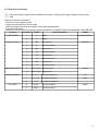
Connector
Pin number
Symbol
Terminal description
Rating
POWER SUPPLY
RELAY OUTPUT
ANALOGUE OUTPUT
ANALOGUE INPUT
AUX. SUPPLY
1
N
supply
2
L
supply
3
NO1
4
C1
5
NO2
6
C2
7
NO3
8
C3
9
NO4
10
C4
11
Out 4-20mA
analogue output
12
Out 4-20mA
signal ground
13
In: +V
analogue voltage input
10V
14
In: +mA
analogue current input
20mA
15
In: 0V
analogue input common
16
24VDC: -
aux supply negative
17
24VDC: +
aux supply positive
AL1 relay NO
AC 90-260V 50/60Hz
1A/250VAC
AL1 relay common
AL2 relay NO
AL2 relay common
AL3 relay NO
AL3 relay common
AL4 relay NO
AL4 relay common
4-20mA
24VDC
4