1
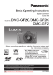
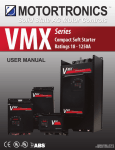
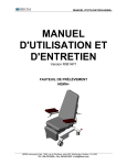
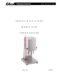
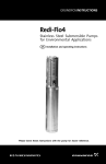
ME2 Series
Micro AC Drives
INSTALLATION & START-UP
MANUAL
REV3
9081101MN
CTi Automation - Phone: 800.894.0412 - Fax: 208.368.0415 - Web: www.ctiautomation.net - Email: [email protected]
Motortronics
ME2 Series
Micro AC Drives
Thank you for purchasing this Motortronics ME2 Series variable
frequency AC drive. When properly installed, operated and maintained,
the ME2 will provide a lifetime of reliable operation. It is mandatory
that the person who operates, inspects, and maintains this equipment
thoroughly reads and understands this manual. This will insure safe
and reliable operation of the controller.
This unit has been put through demanding tests at the factory prior to
shipment. Before unpacking check the following:
• Verify that the model number on the box matches your
purchase order.
• Inspect for possible shipping damage (if damaged, notify
the freight carrier and file a claim within 15 days of receipt).
After unpacking, please check the following:
• Verify that the label specifications match your application
requirement.
• Check all electrical connections and screws. Verify that
there is no visible damage to any of the components.
Warning! Do not service equipment with voltage applied!
Unit can be a source of fatal electrical shock! To avoid
shock hazard, disconnect main power and wait until the
LED on the main control board goes out before working
on the control. Warning labels (not supplied) must be
attached to terminals, enclosure and control panel.
Unit does not provide overspeed protection or incorporate
current limiting control.
To obtain optimum operation from your ME2 Series drive, it is
strongly recommended that this manual is read and
understood.
CTi Automation - Phone: 800.894.0412 - Fax: 208.368.0415 - Web: www.ctiautomation.net - Email: [email protected]
Table of Contents
Chapter 1 General Information ................................................ 1
1.1
Introduction
1.2
Specifications
1.3
Mounting Dimensions/ Terminal Block Location
Chapter 2 Power and Control Wiring ..................................... 5
2.1
Power and Control Wiring
2.2
Wiring Diagram
2.2.1 Power Terminal Block ( TM1 )
2.2.2 Control Terminal Block ( TM2)
2.2.3 External Control Signal Selection ( SW1 )
Chapter 3 Keypad Operation and Programming ................... 10
3.1
Keypad Operation
3.2
Easy Programming
3.3
List of Parameters
3.4
Parameter Function Description
Chapter 4 Fault Codes .............................................................. 25
4.1
Failure or Trip which cannot be reset by Reset Key
4.2
Failure or Trip which can be reset by Reset Key but cannot
be Auto Reset
4.3
Failure or Trip which can be Auto Reset or reset by Reset
Key
4.4
Operational Stop Indications
4.5
Operation Error Indications
Chapter 5 Other Information .................................................... 29
5.1
Selecting AC Line/Load Reactors
5.2
Record of Drive Settings
CTi Automation - Phone: 800.894.0412 - Fax: 208.368.0415 - Web: www.ctiautomation.net - Email: [email protected]
CTi Automation - Phone: 800.894.0412 - Fax: 208.368.0415 - Web: www.ctiautomation.net - Email: [email protected]
Me2 Series
Installation Manual
Chapter 1 - General Information
1.1- Introduction
The Motortronics ME2 Series is a high performance generalpurpose micro AC drive that incorporates a high efficiency
Pulse Width Modulated (PWM) design and IPM technology.
The output closely approximates a sinusoidal current
waveform to allow variable speed control of any conventional
squirrel cage AC induction motor.
1.2 - Specifications
Input Voltage
50/60 Hz (±5%)
Output Voltage
Control Method
Ratings
Motor KW
Motor HP
Current A
Capacity KVA
Weight lbs
Ratings
Motor KW
Motor HP
Current A
Capacity KVA
Weight lbs
1P2 thru 101: Single phase
110 ~ 120V (-15% ±10%)
2P2 thru 203: Single phase
200 ~ 240V (+10%/-15%)
p
401 thru 403: Three phase 380 ~ 460V
Sinusoidal wave PW M control (PNP type 12
- 24V)
1P2
0.2
1/4
1.4
0.53
1.5
Model Number (ME2-XXX-M)
1P5 101 2P2 2P5 201 202 203
0.4 0.75 0.2 0.4 0.75 1.5 2.2
1/2
1
1/4 1/2
1
2
3
2.3 4.2 1.4 2.3 4.2 7.5 10.5
0.88 1.6 0.53 0.88 1.6 2.9 4.0
1.5 1.5 1.6 1.7 1.8 3.8 3.8
401
0.75
1
2.3
1.7
3.5
Model Number (ME2-XXX-M)
402 403
1.5 2.2
2
3
3.8 5.2
2.9
4
3.5 3.6
Me2 Series
-1-
1.2 - Specifications
Approvals
Mounting
Digital Display
UL, cUL, CE
Direct or optional DIN rail mount (for <1 HP
drives)
Indicates, frequency, parameter
selection, fault record
Frequency Control
1.2.1 - Frequency Control
Range
1 - 200 Hz
Resolution
Digital: 0.1 Hz (0-99.9Hz)
1 Hz (100 -120 Hz)
Analog: 1 Hz (60Hz)
Setting
Signal
Digital Keypad; 0-10VDC,
0-20mA, 10K Pot
Limit
Frequency upper/lower limit
Carrier
Frequency
4 ~ 16 kHz
1.2.2 - Control Characteristics
Me2 Series
-2-
Protective Function
1.2.3 - Protective Functions
Overload
Over-voltage
Under-voltage
150% for 1 minute
DC-bus voltage > 410 V
DC-bus voltage < 200 V
Momentary Power
Loss
0-2 seconds (can be restarted
via speed search)
Stall prevention
During accel/decel/constant
speed
Output short circuit
Provided by electronic circuit
Ground fault
Provided by electronic circuit
during start-up and run
Other protection
Heatsink fin overtemp, current
limit
1.2.4 - Environmental Specifications
Ambient Temperature
- 10 to + 40° C
(14° to 104° F)
Humidity
≤ 95% relative, noncondensing
Vibration
Under 1G
EMC
Class A filter standard in all
200 volt units
rated 1/4 thru 1 HP;
Optional Class B for all other
units
Enclosure
Panel Mount / IP20
Me2 Series
-3-
1.3 - Mounting Dimensions
C
DATA
RESET
RUN
STOP
D
ENT
A
DSP
FUN
TM2
TM1
GROUND
TM2
F
FRONT VIEW
SIDE VIEW
TM1
C
BOTTOM VIEW
E
B
ME2 Dimensions
Overall
Dimensions
Model
ME2-1P2-M
ME2-1P5-M
ME2-2P2-M
ME2-2P5-M
ME2-201-M
ME2-202-M
ME2-203-M
Mounting
Dimensions
A
B
C
D
E
F
5.2
2.8
4.6
4.6
2.4
0.18
5.63
4.65
6.76
5.0
4.25
0.18
Me2 Series
-4-
Me2 Series
Installation Manual
Chapter 2 - Power and Control Wiring
2.1 - Power and Control Wiring
This chapter deals with recommended power wiring practices
for the ME2 Series AC drive. Remember, you must always
conform to the National Electrical Code (NEC) and any
applicable local codes. Always make sure the keypad is off,
the LEDs are off, and the DC bus is discharged before adding
or changing any wiring.
Warning! This section involves working with potentially
lethal voltage levels! Caution must be used to
prevent personal harm. Do not service
equipment with voltage applied! To avoid shock
hazard, disconnect main power and wait until
the LED on the main control board goes out
before working on the control. Warning labels
(not supplied) must be attached to terminals,
enclosure and control panel.
• DO NOT touch any circuit components while AC
power is on or immediately after the main AC
power is disconnected from the unit. Wait until
the LED on the control board goes out.
• DO NOT make any connections to the drive
before the unit is disconnected from the AC
power. Failure to adhere to this warning could
result in serious or lethal injury.
• Only use in a pollution degree 2 macro-environment or equivalent.
Me2 Series
-5-
•
•
•
•
Never connect the input power wiring to the
drive terminals T1, T2, or T3.
Always use UL/CSA approved wire and ring lugs.
Always make a positive ground termination to
the Earth terminal of the drive.
Use copper conductors only and size field wiring
based upon 75º wire only.
Maximum
Input Fuse
(Time Delay)
Maximum Input
Circuit Breaker
(Amps)
ME2-1P2
8
10
ME2-1P5
12
20
ME2-2P2
4.5
10
ME2-2P5
8
10
ME2-201
12
20
ME2-202
20
30
ME2-203
30
40
Model
Number
Power
Wiring
Control
Wiring
Copper
Ground
Wiring
14 AWG
14-12 AWG
22-18 AWG
12 AWG
12-10 AWG
10 AWG
Notes:
1. 240 VAC units are suitable for use on a circuit capable
of delivering not more than 5000 RMS symmetrical
amperes, 240 Volts maximum.
2. Always ensure that values used conform to NEC and
all applicable local codes.
Note: Keypad operator cannot be removed.
Me2 Series
-6-
2.2 - Me2 Wiring Diagram
Braking Resistor
(Optional)
P
R
L1 (R)
(U) T1
Incoming
Power
L2 (S)
L3 (T)
3
4
Multi-function
Input
6
7
5
8
9
10K Ω
(W) T3
FWD
REV
1
SP1
RST
Multi-function
Output
2
12V (Internally Supplied)
+10V
MVI
(0~10V/0~20mA, 4-20mA)
10
0~10V
Frequency
Meter
M
(V) T2
11
0V (FM-)
FM+
Grounding
*NOTE: L3(T) is only used on ME-202 and ME-203
2.2.1- Power Terminal Block (TM1)
Notes:
1. Tightening torque for TM1
is 1 lbs-ft or 12 lbs-in.
2. Use copper conductors
only. Size field wiring
based on 75ºC wire only.
3. Wire voltage rating must
be a minimum of 300V.
4. Ratings of the terminal
block (TM1) are 300V, 15A
Symbol
Function Description
L1 (R)
L2 (S)
AC power source input
L3 (T)
P
R
External braking resistor
(only for Me2202/203/401/402/403
T1 (U)
T2 (V)
T3 (W)
Me2 Series
-7-
Drive output to the motor
2.2.2- Control Terminal Block ( TM2 )
Function Description
1
2
Programmable output (Fn21)
Rated 250VAC/30VDC, 1A
3
FWD
4
REV
5
+12V
Common point of terminals 3 / 4 / 6 / 7
6
SP1
Multifunction input terminals (refer to Fn20)
7
RESET
8
9
0V
(FM-)
10
11
FM+
Operation control terminals (refer to Fn03)
Multifunction input terminal 2 (Fn20)
+10V
Power terminal of potentiometer
(High side of potentiometer)
Analog input point
Analog frequency signal input
terminal (wiper of potentiometer
or positive terminal of 0~10V /
4~20mA/ 0~20mA)
Analog common
point
Analog signal common point
(Low side of potentiometer or
negative terminal of 0~10V /
4~20mA / 0~20mA)
Analog output
positive connection
point
Multifunction analog output
terminal
Output terminal signal is
0~10VDC
Notes:
1. Tightening torque for TM2 is 0.42 lbs-ft or 5.03 lbs-in.
2. Use copper conductors only. Size field wiring based
on 75ºC wire only.
3. Wire voltage rating must be a minimum of 300V.
4. Control wiring should not run in the same conduit or
raceway with power or motor wiring.
Me2 Series
-8-
2.2.3- External Control Signal ( SW1 )
SW1 is located in a compartment on the side of the AC
drive.
Switch
External Signal Type
I
V
1
2
3
I
V
1
2
3
0~20mA analog signal ( When Fn11 is set to 1 )
4-20mA analog signal ( When Fn11 is set to 2 )
0~10 VDC analog signal ( When Fn11 is set to 1 )
Remove cover to reveal switch
Me2 Series
-9-
Me2 Series
Installation Manual
Chapter 3 - Keypad Operation and Programming
3.1 - Keypad Operation
Refer to this section if the
keypad will be used to control
the drive and if no external
control connections are
required. This section can also
be used when testing the drive
without control connections.
Note: Keypad operator cannot be
removed.
3.2 - Easy Programming
The ME2 Series has two basic loops:
Operation Loop- changes frequency to increase/decrease
motor speed
Programming Loop- changes function settings
Me2 Series
-10-
Programming
Loop
POWER ON
Change
Function?
DSP
FUN
∧
Displays
Frequency
Press this key to
reach function
to be changed
Note:
DSP
FUN
Press this key to
go to new setting
Press this key to
DATA enter new
ENT function setting
DSP
FUN
Press this key to
reach function to
be changed
Press this key to
RUN
start/stop the
STOP
motor
Press this key to
DATA read existing
ENT function setting
∧
Change
Frequency?
∧
Press this key to
display function
number (FXX)
Operation
Loop
Press this key to return to
frequency display or skip this
key to continue changing functions.
Me2 Series
-11-
This key allows
you to switch
from one loop to
the other
3.3- List of Parameters
Function
Accel/Decel time
FN
Unit
Range
Factory
Setting
Acceleration time [Notes: 1, 2]
0.1 sec
0.1~999 S
5.0 S
Function Description
0
Factory Adjustment
1
000
2
Deceleration time [Notes: 1, 2]
0.1 sec
0.1~999 S
5.0 S
Operation mode
3
0: Forward / Stop, Stop / Reverse
1: Run / Stop, Reverse / Forward
1
0~1
000
Motor rotation
direction
4
0: Forward
1: Reverse
[Note:1]
1
0~1
000
V/F pattern
5
V/F pattern setting
[Notes: 3, 4]
1
1~6
4
Frequency
upper/lower limit
6
Frequncy upper limit
[Notes: 2, 3, 4]
60 Hz
0.1Hz
0.0~200 Hz
7
Frequency lower limit [Note: 2]
SP1 frequency
8
SP1 frequency [Note: 2]
10 Hz
JOG frequency
9
JOG frequency [Note: 2]
6 Hz
Operation
Control
Frequency
Control
0: Keypad
10
1: External control
11
0: Keypad
1: 0 ~ 10V, 4 ~ 20mA, 10K pot
(no offset)
2: 2 ~ 10V, 4 ~ 20mA
(with 20% offset)
000
1
0~1
000
1
0~2
000
Notes:
1. Can be changed during running mode.
2. If the setting is between 0.1 and 1, the display
increments in 0.1 units. If the setting is equal to or
greater than 1, the display increments in units of 1.
3. Refer to Fn25.
4. Factory set default settings depend on Fn25
programming.
Me2 Series
-12-
3.3- List of Parameters (continued)
Function
Carrier frequency
FN
Torque
compensation
Stopping mode
14
Factory
Setting
1
1~10
5
0.1%
0.0~10.0%
000
1
0~1
000
0.1 sec
0.0~25.5 S
0.5 S
0.1 Hz
1~10 Hz
1.5 Hz
0.10%
0.0~20.0%
8.0%
1%
0-200%
100%
0:Decelerate to stop
1: Coast to stop
15 DC braking time
16
DC braking injection
frequency
17 DC braking level
Electronic
Thermal
Overload
Range
12 Carrier frequency setting
Torque
13 compensation gain
[Note: 1]
DC
Braking
Setting
Unit
Function Description
Based on drive rated
18
current
19 Multifunction Input (TM1)
Programmable
Inputs
20 Multifunction Input (TM2)
1:
2:
3:
4:
5:
6:
Jog
SP1
Emergency Stop
External Base Block
Reset
SP2
2
5
Notes:
1. Can be changed during running mode.
2. If the setting is between 0.1 and 1, the display
increments in 0.1 units. If the setting is equal to or
greater than 1, the display increments in units of 1.
3. Refer to Fn25.
4. Factory set default settings depend on Fn25
programming.
Me2 Series
-13-
3.3- List of Parameters (continued)
Function
Programmable
Output
Reverse Mode
Lockout
Momentary
Power
Loss Restart
Auto Restart
Factory Setting
SP2 Frequency
SP3 Frequency
Software
version
Fault History
FN
Function Description
21 Multifunction Output
22
0: REV run enabled
1: REV disabled
0: Enabled
23
1: Disabled
24 Number of auto-restart times
010: Constants initialized
to 50 Hz system
25
020: Constants initialized
to 60 Hz system
26 SP2 Frequency [Note: 2]
27 SP3 Frequency [Note: 2]
28 Reserved for future use
29 CPU program version
Unit
Range
1: Running
2: At set speed
3: Fault
1
0~1
Factory
Setting
3
000
1
0~1
000
1
0~5
000
000
0.1 Hz
0.1 Hz
0.0~200
0.0~200
20
30
1.8
30 Last 3 faults in memory
Notes:
1. Can be adjusted during running mode.
2. If the setting is between 0.1 and 1, the display
increments in 0.1 units. If the setting is equal to or
greater than 1, the display increments in units of 1.
3. Refer to Fn25.
4. Factory set default settings depend on Fn25
programming.
Me2 Series
-14-
3.4 - Parameter Function Description
Fn00 Factory set. Do not change.
Fn01 - Acceleration time
Factory Setting = 5 seconds; Range = 0.1 ~ 999 sec
Fn02 - Deceleration time
Factory Setting = 5 seconds; Range = 0.1 ~ 999 sec
1. Acceleration/deceleration time calculation formula:
Acceleration time = Fn01 x Setting Frequency
60Hz
Deceleration time = Fn02 x Setting Frequency
60Hz
Fn03 - Operation mode selection - Factory Setting = 000
Range = 0 : Forward / Stop , Reverse / Stop
= 1 : Run / Stop , Forward / Reverse
FN03 = 0
3 FWD/Stop
4 REV/Stop
3 Run/Stop
4 FWD/REV
5 Com
5 Com
FN03 = 1
TM2 PIN3
TM2 PIN4
Fn3 = 0
Forward
*
Reverse
Fn3 = 1
(note)
Forward
Reverse
*
Note: Fn03 active only when Fn10 = 1 (external control)
*Reverse command is ignored when Fn22 = 1
Me2 Series
-15-
Fn04 - Motor rotation direction
Factory Setting = 0
Range = 0 : forward
= 1 : reverse
Note: When Fn22 = 1 : (Reverse disabled),
Fn04 cannot = 1. Keypad indication will display “LOC”.
Fn05 - V/F pattern
Factory Setting = 4; Range = 1- 6
Select one of six fixed V/F patterns :
Application
General Application
Fn5 Setting
4
Variable torque
5
V (%)
60 Hz
High starting torque
6
V (%)
V (%)
100
100
100
B
B
B
V/F pattern
C
C
1
Application
3.0 60
Hz
120
General Application
Fn5 Setting
3.0
Hz
60 120
30
1
High starting torque
1
60
Hz
120
Variable torque
2
V (%)
50 Hz
C
1
3
V (%)
V (%)
100
100
100
B
B
B
C
C
V/F pattern
1
2.5 50
Hz
120
C
1
Me2 Series
-16-
2.5
Hz
50 120
1
25
50
Hz
120
Fn06 - Frequency upper limit
Factory Setting = 60Hz; Range = 0.0 ~ 200Hz
Fn07 - Frequency lower limit
Factory Setting = 0.0; Range = 0 ~ 200 Hz
Notes: 1. If Fn07 = 0 Hz, and the frequency is equal to 0Hz,
the drive will stop at 0 speed.
2. If Fn07 > 0 Hz, and the frequency is less than or
equal to Fn07, the drive output will = Fn07.
Fn08 - SP1 frequency
Factory Setting = 10 Hz; Range = 0 ~ 200 Hz
Fn09 - Jog frequency
Factory Setting = 6 Hz; Range = 0 ~ 200 Hz
1. When Fn19 or Fn20 = 2 and multifunction input
terminal is on, the drive will operate at SP1 frequency
(Fn08)
2. When Fn19 or Fn20 = 1 and multifunction input
terminal is on, the drive will operate at Jog frequency
(Fn09)
3. The priority of using frequency reference is : Jog >
SP1 > Keypad setting or external control signal
Fn10 - Operation Control
Factory Setting = 0
Range = 0 : Keypad operated
= 1 : External control operated (emergency stop on
the keypad is still active)
Me2 Series
-17-
Fn11 - Frequency control
Fn6
Factory Setting = 0
Range = 0 :Frequency reference is set
Fn11=1
via the keypad
Fn11=2
= 1 :Frequency reference is set via
the potentiometer or analog
0mA 4mA
20mA
0V
10V
signal on TM2 with no offset
( 0 ~ 10V / 0 - 20mA )
= 2 :Frequency reference is set via the
potentiometer or analog signal on TM2
with 20% offset (4-20mA )
Note: When Jog frequency or SP1 frequency is switched
on, the frequency is set via the Jog or SP1 speed. The
arrow buttons on the keypad are disabled during
acceleration /deceleration modes and when the multifunction terminal is active. Original settings will be restored
after Jog or SP1 connection is OFF. Ensure correct
selection of SW1 (refer to 2.2.3).
Fn12 - Carrier frequency
Factory Setting = 5; Range = 1 ~ 10 (4 ~ 16 kHz)
Although IGBT type drives can provide low noise under
normal operation, it is possible that the high carrier
frequency may interfere with external electronic
components (or other drives) or even cause vibration in the
motor. Adjusting the carrier frequency can eliminate these
problems.
FN12
Carrier Frequency
FN12
1
4 kHz
6
10 kHz
2
5 kHz
7
12 kHz
3
6 kHz
8
14.4 kHz
4
7.2 kHz
9
15 kHz
5
8 kHz
10
16 kHz
Me2 Series
-18-
Carrier Frequency
Fn13 - Torque compensation gain
Factory Setting = 0; Range = 0 ~ 10 %
Drive output will be the B and C voltage points on the V/F
pattern (refer to Fn05) plus the Fn13 setting. This setting
will enhance the output torque. Note: When Fn13 = 0, the
torque boost function is disabled.
Fn14 - Stopping mode
Factory Setting = 0
Range = 0 : Deceleration to stop
= 1 : Coast to stop
If Fn14 = 0
When the drive receives the stop command, it decelerates
to the frequency set point of Fn16. The DC braking will
start at the level set in Fn17. After the time duration (set in
Fn15), the drive will stop.
If Fn14 = 1
The drive output stops immediately after receiving a stop
command. The motor will enter a free running state and
coast to a stop.
Fn15 - DC braking time
Factory Setting = 0.5; Range = 0 ~ 25.5 seconds
Fn16 - DC braking starting frequency
Factory Setting = 1.5; Range = 1 ~ 10 Hz
Fn17 - DC braking level
Factory Setting = 8.0; Range = 0 ~ 20 %
Me2 Series
-19-
Fn18 - Electronic Thermal Overload
Factory Setting = 100; Range = 0 ~ 200 %
1. Function of the electronic thermal overload
protecting the motor
1. Motor rated current = Drive rated current x Fn18 or
Fn18 = Motor rated current / drive rated current
Fn5 = 4,5,6
60 Hz standard motor
Fn5 = 1, 2, 3
50 Hz standard motor
Derating %
Derating %
100
90
60
100
90
60
Hz
20
60
Hz
20
50
2. When the load is within 100% of the motor rated current,
the drive will operate continuously. When the load
reaches 150% of the motor rated current, the drive will
trip within 1 minute.
3. After the electronic thermal overload is activated, the
drive output is shut off immediately. OL1 will flash on
the keypad. To resume operation, push the RESET
button or activate the external reset terminal.
4. When operating at low speeds, the motor’s heat
dissipation capability is reduced. The electronic thermal
overload activation level is also reduced. To ensure
proper motor protection, choose an appropriate Fn05
setting.
2. Function of the electronic thermal overload
protecting the drive
1. When the load is within 103% of the drive rated current, the
drive will operate continuously. When the load reaches 150%
of the rated current of the drive, the drive will trip within 1
minute.
Me2 Series
-20-
2. After activation of the drive’s Minute
electronic thermal overload, the
(1)
drive output shuts off immediately.
(2)
1.0
OL2 will flash on the keypad. To
100 150
resume operation, push the
RESET button on the keypad or
activate the external reset terminal.
Fn19 - Multifunction input (TM2 - Pin 6)
Factory Setting = 2; Range = 1 ~ 6
Fn20 - Multifunction input (TM2 - Pin 7)
Factory Setting = 5; Range = 1 ~ 6
1. Fn19, Fn20 = 1 : JOG
2. Fn19, Fn20 = 2 or 6 : Preset Speed Control
Fn Setting
Fn 19 = 2
Fn 20 = 6
Fn 19 = 6
Fn 20 = 2
SP1
Terminal
ON
OFF
ON
ON
OFF
ON
Reset
Terminal
OFF
ON
ON
OFF
ON
ON
Percentage of
Current
Output
Frequency
FN 08 (SP1)
Fn 26 (SP2)
Fn 27 (SP3)
Fn 26 (SP2)
FN 08 (SP1)
Fn 27 (SP3)
3. Fn19, Fn20 = 3 : External emergency stop signal
When the external emergency stop signal is activated, the
drive decelerates to a stop (ignoring the setting in Fn14).
Keypad flashes E.S. after stop. When the emergency stop
signal is deactivated, turn the RUN switch OFF and then ON
again (if Fn10 = 1) or push the RUN key (if Fn10 = 0). The
drive will resume operation and restart. If the emergency
stop signal is removed before the drive stops, it will still execute
emergency stop.
4. Fn19, Fn20 = 4 : External Base Block (immediate
shut off)
When the external base block signal is activated, the
Me2 Series
-21-
drive output immediately shuts off (ignoring the setting
in Fn14). Keypad will flash b.b. after stop. After the base
block signal is deactivated, turn the RUN switch OFF
and then ON again (if Fn10 = 1) or push the RUN key (if
Fn10 = 0). The drive will restart from the starting
frequency.
5. Fn19, Fn20 = 5 : Reset when drive is in fault
condition
Fn21 - Multi-function output
Factory Setting = 3
Range= 1 : Run mode signal
= 2 : At frequency signal
= 3 : Fault signal
Fn22 - Reverse mode lockout
Factory Setting = 0
Range= 0 : REV command enabled
= 1 : REV command disabled
Note: When Fn04 is set to 1 (reverse), Fn22 cannot be set
to 1. Keypad will display “LOC”. Fn04 must be changed to
0 setting (forward) before Fn22 can be set to 1.
Fn23 - Restart after momentary power loss
Factory Setting = 0
Range= 0 : Restart enabled
= 1 : Restart disabled
1. When AC power temporarily drops below the low voltage
protection level the drive will stop immediately. If the power
source returns within 2 seconds, the drive can restart via
speed search (start searching from the previous operating
frequency) or fault, displaying “LV-C”.
2. When Fn23 = 0, if the temporary power loss is less than
2 seconds, the drive will resume operation via speed
search 0.5 seconds after power returns. Fn24 does not
Me2 Series
-22-
limit the number of restarts. If the temporary power loss
is longer than 2 seconds, automatic restart will be
determined by the setting of Fn24.
3. When Fn23 = 1, the drive will stop immediately after the
temporary power loss and display “LV-C” on the keypad.
The drive will not restart automatically. (Not controlled
by Fn24)
Fn24 - Number of Auto-restart times
Factory Setting = 0; Range = 0 ~ 5
1. When Fn24 = 0, the drive will not automatically restart
if the power loss period is longer than 2 seconds.
2. When Fn24 > 0, the drive will resume operation via
speed search 0.5 secs after power returns. The drive
will accelerate or decelerate to the frequency setting.
3. When the drive is set to decelerate to stop (Fn14) or
DC braking (Fn17) the transient restart procedure is not
performed.
4. When either of the following occur, the auto-restart
counter will be reset:
1. No additional faults (during operation or stop)
occur within 10 minutes of restart.
2. RESET is pressed or external RESET is
activated.
Fn25 - Factory setting - Factory Setting = 000
Range= 010 : Constants set for 50Hz system
= 020 : Constants set for 60Hz system
1. When Fn25 is set to 010, all parameters are restored to
settings for 50Hz operation. The settings of Fn05 and
Fn06 are reset to 1 and 50 respectively. Fn25 is restored
back to 000 after the reset process is complete.
2. When Fn25 is set to 020, all parameters are restored to
the original factory settings for 60Hz operation. The
Me2 Series
-23-
settings of Fn05 and Fn06 are reset to 4 and 60
respectively. Fn25 is restored back to 000 after the reset
process is complete.
Fn26 - SP2 Frequency
Factory Setting = 20 Hz; Range = 0.0 ~ 200 Hz
1. Fn26 establishes the second of three preset command
frequencies. Used to configure a specific speed for multistep applications.
Fn27 - SP3 Frequency
Factory Setting = 30 Hz; Range = 0.0 ~ 200 Hz
1. Fn27 establishes the third of three preset command
frequencies. Used to configure a specific speed for multistep applications.
Fn28 : Reserved
Fn29 - Software (program) version
- Factory Setting = 1.8
Fn30 : Fault trace
1. Keypad will indicate the sequence of the occurrence
of faults by location of the decimal point:
x.xx = the most recent fault
xx.x = the previous fault
xxx. = the earliest fault in the record
2. When entering the Fn30 function, the x.xx record will
be displayed first. Pressing the /\ button will read out
xx.x then xxx. then x.xx consecutively.
3. When entering Fn30 function, if the RESET button is
pressed, the fault record will be cleared. Indication
display will show -.--, --.- and ---.
4. Example: When the content of fault memory indicates
O.CC, the latest fault was OC-C (over current during
constant speed).
Me2 Series
-24-
Me2 Series
Installation Manual
Chapter 4 - Fault Codes
4.1 - Failure or Trip which cannot be reset by Reset Key
FAULT CODE
CONTENT
PROBABLE CAUSE
WHAT TO DO
CPF
Program Error
High electronic noise
Install RC type suppressor on
all contactor/brake coils
EPR
EEPROM error
EEPROM defective
Replace Drive
OV
Over voltage
in stop mode
Detection circuit is
damaged
Replace Drive
LV
Low voltage
in stop mode
1. Input voltage too low
2. Detection circuit is
damaged
1. Correct Input voltage
2. Replace Drive
OH
1. Ambient temperature is
Heatsink overheat high or ventilation is poor
during stop mode 2.Detection circuit is
damaged
Me2 Series
-25-
1. Replace Drive
2. Improve Ventilation
4.2 - Failure or Trip which can be reset by Reset Key
but cannot be Auto Reset
FAULT CODE
CONTENT
PROBABLE CAUSE
WHAT TO DO
OC
Over-current
Detection circuit failure
during stop mode
OL1
Motor over-load
1. Excessive load
2. Incorrect V/f pattern
3. Improper Fn18 setting
1. Select a larger HP unit
2. Select correct V/f pattern
3. Adjust Fn18 according to
instructions
OL2
Drive over-load
1. Excessive load
2. Incorrect V/f pattern
1. Select a larger HP unit
2. Select correct V/f pattern
Me2 Series
-26-
Replace Drive
4.3 - Failure or Trip which can be Auto Reset or reset
by Reset Key
FAULT CODE
CONTENT
PROBABLE CAUSE
1. Motor is shorted
2. Motor is grounded
3. Transistor module
damaged
1. Acceleration time setting
too short
2. Wrong V/f pattern
3. Motor exceeds unit rating
WHAT TO DO
1. Inspect/repair motor
2. Remove grounding point
3. Replace Drive
OCS
Over-current
during start
OCA
Over-current
during
acceleration
OCC
Over-current
during constant
speed
1. Transient loading
2. Input voltage fluctuations
1. Check load condition
2. Install a reactor between the
power supply and the Drive
OCd
Over-current
during
deceleration
1. Deceleration setting
too short
1. Extend deceleration time
OCb
Over-current
during braking
DC braking frequency,
braking voltage, or braking
time setting too high
Reduce settings of Fn15,
Fn16, or Fn17
OVC
Over-voltage
during constant
speed operation
1. Deceleration time is set
too short or load inertia is
too high
2. Input voltage fluctuations
1. Extend deceleration time
2. Correct line voltage problem
LVC
Low Voltage
during constant
speed
1. Input voltage too low
2. Input voltage fluctuations
1. Correct input voltage
2. Correct line voltage
OHC
Overheat during
constant speed
1. Load is too great
2. Ambient temperature too
high or poor ventilation
1. Check load
2. Limit ambient temperature
or improve ventilation
Me2 Series
-27-
1. Extend acceleration time
2. Select correct V/f pattern
3. Select larger HP unit
4.4 - Operation Stop Indications
FAULT CODE
WHAT TO DO
CONTENT
SP0
Zero speed stop
An SP0 fault code can only occur when Fn7 is set to 0.
If an SP0 fault code occurs and Fn11=0, use the keypad to
increase the speed above 1 Hz.
If an SPO fault code occurs and Fn11=1, increase the
value of the external analog signal.
SP2
Keypad
emergency stop
If Fn10 = 1 and the STOP key on the keypad
is pressed during operation, the drive will
stop according to the setting in Fn14 and stop.
Keypad will flash E.S. after stop.
(Refer to instruction for Fn19 for details.)
E.S.
External
emergency stop
When the external emergency stop signal is activated
via the multi-function input terminal, the drive will
decelerate and stop. Keypad will flash E.S. after stop.
(Refer to instruction for Fn19 for details.)
b.b.
External BASE
BLOCK
When the external BASE BLOCK signal is activated
via the multi-function terminal, the drive output will
stop immediately and flash b.b. for indication.
(Refer to instruction for Fn19 for details.)
4.5 - Operation Error Indications
FAULT CODE
LOC
CONTENT
Motor direction
locked
PROBABLE CAUSE
1. Attempted to reverse
direcion when Fn22 = 1
2. Attempted to set Fn22 to
1 when Fn04 = 1
ER1
1. Press UP or DOWN arrow
keys when Fn11 = 1 or
under SP1 operation
2. Attempted to to change
Keypad operation
Fn29
error
3. Attempted to change
parameter that cannot be
changed during run mode.
(Refer to parameter list)
ER2
Parameter setting
1. Fn6 < or = Fn7
error
Me2 Series
-28-
WHAT TO DO
1. Change Fn22 to 0
2. Change Fn04 to 0
1. Use UP or DOWN
arrow keys to adjust
frequency setting after
changing Fn11 = 0
2. Do not change Fn29
3. Change function during
stop mode
1. Change so Fn6 > Fn7
Me2 Series
Installation Manual
Chapter 5 - Other Information
5.1 - Selecting AC Line/Load Reactors
Model
Reactor
Current Value ( A )
Inductance ( m H )
ME2-2P2-M
3.0
7.0
ME2-2P5-M
5.2
4.2
ME2-201-M
9.4
2.1
ME2-202-M
19.0
1.1
ME2-203-M
25.0
0.71
Me2 Series
-29-
5.2 - Record of Settings
Customer
Model
Application
Telephone
Address
Fn##
Value
Fn##
Value
Fn##
Fn00
Fn11
Fn22
Fn01
Fn12
Fn23
Fn02
Fn13
Fn24
Fn03
Fn14
Fn25
Fn04
Fn15
Fn26
Fn05
Fn16
Fn27
Fn06
Fn17
Fn28
Fn07
Fn18
Fn29
Fn08
Fn19
Fn09
Fn20
Fn10
Fn21
Value
Fn30
CTi Automation - Phone: 800.894.0412 - Fax: 208.368.0415 - Web: www.ctiautomation.net - Email: [email protected]