1
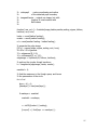
AUTOMATED IRIS RECOGNITION SYSTEM
USING CMOS CAMERA WITH PROXIMITY
SENSOR
by
Paulo R. Flores
Hazel Ann T. Poligratis
Angelo S. Victa
A Design Report Submitted to the School of Electrical Engineering,
Electronics Engineering, and Computer Engineering in Partial
Fulfilment of the Requirements for the Degree
Bachelor of Science in Computer Engineering
Mapua Institute of Technology
September 2011
i
ii
ACKNOWLEDGEMENT
It is with great pleasure that we acknowledge the efforts of those individuals
who have taken part to the development of this study.
We would like to thank our adviser, Engr. Ayra Panganiban for guiding us and
sharing her time and knowledge on the study. To the panel members who have
allotted their time for our oral presentation and for checking our paper for the
necessary revisions;
To our professor, Engr. Noel Linsangan, who tolerantly helped us with the
necessary revisions needed for our paper, provided us handy guidelines and
documents for the completion of this project and inspired us to strive for the
betterment of our research;
To our friends and colleagues who helped and supported us with this design;
To our parents, for their unending support and encouragement; and
Above all, we humbly give our sincerest gratitude to the Almighty God for giving
us the strength, patience, unfading guidance and for imparting us the wisdom to
accomplish this paper.
iii
TABLE OF CONTENTS
TITLE PAGE
i
APPROVAL SHEET
ii
ACKNOWLEDGEMENT
iii
TABLE OF CONTENTS
iv
LIST OF TABLES
vi
LIST OF FIGURES
vii
ABSTRACT
viii
Chapter 1: DESIGN BACKGROUND AND INTRODUCTION
1
BACKGROUND
1
STATEMENT OF THE PROBLEM
2
OBJECTIVES OF THE DESIGN
3
IMPACT OF THE DESIGN
3
DESIGN CONSTRAINTS
4
DEFINITION OF TERMS
5
Chapter 2: REVIEW OF RELATED DESIGN LITERATURES AND STUDIES
10
IRIS RECOGNITION TECHNOLOGY
10
IMAGE QUALITY
11
IMAGE QUALITY METRICS
11
PROXIMITY SENSOR
14
IRIS IMAGE ACQUISITION
14
iv
IRIS RECOGNITION SYSTEM AND PRINCIPLES
15
BIOMETRIC TEST METRICS
16
Chapter 3: DESIGN PROCEDURES
19
HARDWARE DEVELOPMENT
20
SOFTWARE DEVELOPMENT
26
PROTOTYPE DEVELOPMENT
28
Chapter 4: TESTING, PRESENTATION AND INTERPRETATION OF DATA
34
SENSOR OUTPUT TEST
34
IMAGE QUALITY TEST
36
DATASETS
40
IMPACT ANALYSIS
42
Chapter 5: CONCLUSION AND RECOMMENDATION
44
BIBLIOGRAPHY
47
APPENDIX
49
APPENDIX A - Operation‘s Manual
49
APPENDIX B - Pictures of Prototype
57
APPENDIX C - Program Listing
58
APPENDIX D - Data Sheets
108
APPENDIX E - IEEE Article Format
124
v
LIST OF TABLES
Table 4.1: Proximity Sensor Settings
34
Table 4.2: Sensor Output Testing
35
Table 4.3: Camera Specifications
36
Table 4.4: Iris Image Quality Assessment
38
Table 4.5: Enrolled Captured Iris Images
40
Table 4.6:
Inter-class comparisons of Haar wavelet at Level 4 vertical coefficient
41
Table 4.7:
Intra-class comparisons of Haar wavelet at Level 4 vertical coefficient
42
vi
LIST OF FIGURES
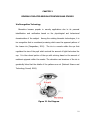
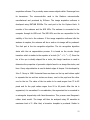
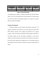
Figure 2.1: Iris Diagram
10
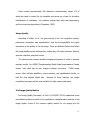
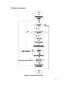
Figure 3.1: Conceptual Framework
20
Figure 3.2: Block Diagram
21
Figure 3.3: Schematic Diagram
24
Figure 3.4: System Flowchart
26
Figure 3.5: Relational Model
28
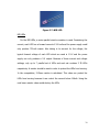
Figure 3.6: 5-V Power Supply
29
Figure 3.7: NIR LED
30
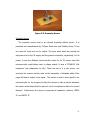
Figure 3.8: Proximity Sensor
31
Figure 3.9: Gizduino
32
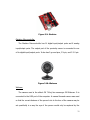
Figure 3.10: Webcam
32
Figure 4.1: Selected Iris images from Engr. Panganiban‘s system
37
Figure 4.2: Selected Iris images from the current system
38
vii
ABSTRACT
Biometrics is becoming popular nowadays due to its very useful security
application. These technologies use the unique characteristics of an individual in
an electronic system for authentication. There are numbers of biometrics
technology and among those; the iris recognition technology is considered the
most reliable since human iris is unique and cannot be stolen. The purpose of
this design is to improve an existing iris recognition system developed by Engr.
Panganiban which is entitled ―CCD Camera with Near-Infrared Illumination for
Iris Recognition System‖. The proposed design aims to automate the existing iris
recognition system through the use of the following materials: webcam, Gizduino
microcontroller, NIR LEDs, power supply, and a proximity sensor. The NIR LEDs,
which illuminates the iris, were placed in a circular case attached in the webcam.
The iris image that would be captured in this design would only produce little
noise since the light produced by the NIR LEDs would be pointing to the pupil of
the eye and thus, the iris image template would not be affected. The automation
block as its name implies, automates the capturing of the webcam through the
use of the sensor, that is connected to the microcontroller in which is handled by
the image acquisition software. An additional feature of this design is the realtime processing of image. Once the iris was captured, the software would
automatically perform iris segmentation, normalization, template encoding and
template matching. It would then display if your iris is authenticated (enrolled) or
not. In matching the templates, when the Hamming distance value is greater
than or equal to 0.1060, the iris templates do not match but when the HD value
is less than 0.1060, the iris template are from the same individual. In comparing
the accuracy of the iris templates in our design, the Degrees-of-Freedom (DoF)
was computed. The computed DoF of our design is 80, which is higher than that
of Engr. Panganiban‘s work.
Keywords: biometrics, iris recognition, hamming distance, wavelet, real-timeimage processing.
viii
Chapter 1
DESIGN BACKGROUND AND INTRODUCTION
BACKGROUND
Biometrics is becoming popular nowadays due to its very useful security
applications. The technology uses the unique characteristics of an individual in an
electronic system for authentication. Biometric technologies, used as a form of
identity access management and access control, are becoming the foundation of
an extensive array of highly secure identification and personal verification
solutions. There are several of applications for biometrics which include civil
identity, infrastructure protection, government/public safety and the like. As for
the main intention of this design is to implement it for security function since it is
very useful to this field having a fact that an iris of a human is the most unique,
even for a person, the left iris has different pattern of wavelets compared to that
of the right iris of the same person. This design includes an automated CMOS
camera and proximity sensor for iris recognition system. A CMOS camera, or
complementary metal oxide semiconductor camera, has a CMOS image sensor in
which has an ability to integrate a number of processing and control functions.
These features include timing logic, exposure control, white balance and the
likes. The proximity sensor automates the camera. The sensor decides on
whether the target is positioned for capture. The required input information is
the iris image of a person for the iris recognition system database. The image
1
will be processed and analyzed by the built-in algorithm in MATLAB. The iris
image will be stored in the database as stream of bits. These bits will serve as
the identification of the person who enrolled it and will also be used for template
matching, a process of finding the owner of the iris template by comparing every
iris template in the database.
STATEMENT OF THE PROBLEM
The existing Image Acquisition of the Iris Recognition System developed by
Panganiban (2009), entitled ―CCD Camera with Near-Infrared Illumination for Iris
Recognition System‖ recommends the enhancement of the device to improve the
performance of the system. The purpose of this innovation is to answer the
following questions:
1.
Since quality image affects the critical success of iris image enrolment.
What camera should be used to get a better quality image to get a clear detail of
the captured iris image?
2.
What are the additional components and changes needed, and how can
an installation of proximity sensor automate and enhance the precision of the
camera and improve the matching rate of accuracy?
2
OBJECTIVES OF THE DESIGN
The primary objective of this design is to automate and improve the existing
Image Acquisition of the Iris Recognition System by Engr. Panganiban.
Specifically, for the success of this design, the following objectives must be met;
1. The Camera to be used, with the help of the NIR LEDs, must be able to
produce an image of the subject‘s iris.
2. NIR LEDs must be located where it would give enough IR light to the
subject‘s iris. This would help make the iris more visible to the camera and
to the image for capture.
3. The Proximity sensor should be installed to the system which would detect
whether the person is at the correct distance and position before capturing
the subject‘s iris.
4. The system must be able to recognize the difference between the irises to
be processed through Hamming distance values and show the separation of
classes through degree-of-freedom (DoF).
5. The system must have a DoF improvement on Engr. Panganiban‘s design.
IMPACT OF THE DESIGN
The design is an Automated Iris Recognition System; it is generally made for
improving its image acquisition. This would capture an image of the iris.
Nowadays, this biometric technology shows an increasing promise on the
3
security
system
for
it
studies
the
unchanging
measurable
biological
characteristics that are unique to each individual. Among the existing biometric
devices and scanners available today, it is generally conceded that iris
recognition is the most accurate. The design can be used as a prototype which
can be implemented by companies, governments, military, banks, airports,
research laboratories,
border control for security purposes for allowing and
limiting access to a particular information or area. The government officials could
also use this design for identifying and recording information of individuals and
criminals.
Iris recognition technology can be used in places demanding high security.
Physical
access-based
identification,
which
includes
anything
requiring
a password, personal identification number or key for building access or the like,
could be replaced by this technology. Unlike those physical methods of
identification, human iris cannot be stolen. This technology addresses the
problems of both password management and fraud.
DESIGN CONSTRAINTS
Good quality iris image can only be produced if the eye is approximately 3 to
4 cm away from the camera. A solid red light from the proximity sensor would
indicate that the human eye is within the range of 4 to 5 cm. Every time an
object is sensed, the red LED generates a solid light and the camera captures an
4
image of the object. The system does not involve iris image processing and
matching of individuals with eye disorders or contact lenses. Since with these
situations, the iris image will be affected. Also, the system will only work properly
when the captured image is an iris otherwise it will result to an error. The speed
of the system is limited by the computer specifications where the software is
deployed. The recommended system requirements for the software application is
a multi-core 2.20 GHz or higher for the CPU, a 4.00 GB or higher for the RAM
and Windows 7 for the operating system.
DEFINITION OF TERMS
Authentication – the process of determining whether someone or something is
enrolled in the system, or has authorized to be.
Biometrics – the science and technology of measuring and analyzing biological
data; refers to technologies that measure and analyze human characteristics,
such as fingerprints, eye retinas and irises, voice patterns, facial patterns and
hand measurements, for authentication purposes.
Camera – a device that converts images into electrical signals for television.
5
CMOS / Complementary Metal-Oxide Semiconductor - a semiconductor
technology used in the transistors that are manufactured into most of
microchips.
Database – the collection of data on computer; a systematically arranged
collection of computer data, structured so that it can be automatically retrieved
or manipulated.
De-noising – the extraction of a signal from a mixture of signal and noise.
Enrolment – the process of putting something on a database for the first time.
Focus – the point where rays of light, heat, etc. or waves of sound come
together, or from which they spread or seem to spread; specifically, the point
where rays of light reflected by a mirror refracted by a lens meet or the point
where they would meet if prolonged backward through the lens or mirror.
Hamming distance – the difference between letter or number sequences: a
measure of the difference between two words or messages, expressed by the
number of characters needing to be changed in one message to obtain the
other.
6
Hardware – physical components of a computer system.
Illumination – an act of illuminating; the provision of light to make something
visible or bright, or the fact of being lit up.
Image – a picture, idea, or impression of a person, thing, or idea; or a mental
picture of a person, thing, or idea.
Image acquisition – image processing, the alteration or manipulation of
images that have been scanned or captured by a digital recording device.
Image capture – employing a device, such as a scanner, to create a digital
representation of an image.
Image quality – used to refer to the degree of visibility of relevant information
in an image.
Infrared – electromagnetic radiation having a wavelength just greater than that
of red light but less than that of microwaves, emitted particularly by heated
objects.
7
Iris – the pigmented, round, contractile membrane of the eye, suspended
between the corneas and perforated by the pupil; regulates the amount of light
entering the eye.
Iris Recognition – a type of pattern recognition of a person‘s iris recorded in a
database for future attempts to determine or recognize a person‘s identity when
the eye is viewed by a reader.
MATLAB / Matrix Laboratory – a high-level programming language for
technical computing from The MathWorks, Natick, MA; used for a wide variety of
scientific and engineering calculations, especially for automatic control and signal
processing. It has an interactive environment that enables you to perform
computationally intensive tasks faster than with traditional programming
language such as C, C++, and Fortran.
Normalization – the process of efficiently organizing data in a database.
Proximity sensor – a sensor that can detect the presence of nearby objects
without any physical contact.
8
Wavelets – a wave-like oscillation with amplitude that starts out at zero,
increases, and then decreases back to zero; a waveform that is bounded in both
frequency and duration.
Sensor – a device, such as a photoelectric cell, that receives and responds to a
signal or stimulus.
Segment – the part into which something is divided.
Segmentation – the process of partitioning a digital image into multiple
segment; in this case, the process of locating the iris region.
Software – a collection of computer programs and related data that provide the
instructions telling a computer what to do and how to do it.
9
CHAPTER 2
REVIEW OF RELATED DESIGN LITERATURES AND STUDIES
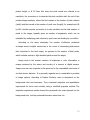
Iris Recognition Technology
Biometrics became popular in security applications due to its personal
identification and verification based on the physiological and behavioural
characteristics of the subject. Among the existing biometric technologies, it is
iris recognition that is considered promising which uses the apparent pattern of
the human iris (Panganiban, 2010). The iris is a muscle within the eye that
regulates the size of the pupil which controls the amount of light that enters the
eye. It is the colored portion of the eye with coloring based on the amount of
melatonin pigment within the muscle. The coloration and structure of the iris is
genetically linked but the details of the patterns are not (National Science and
Technology Council, 2006).
Figure 2.1 Iris Diagram
10
Irises contain approximately 266 distinctive characteristics, about 173 of
which are used to create the iris template and serves as a basis for biometric
identification of individuals. Iris patterns possess high inter-class dependency,
and low intra-class dependency (Daugman, 1993).
Image Quality
According to Kalka, et al., the performance of the iris recognition system,
particularly recognition and segmentation, and the interoperability are highly
dependent in the quality of the iris image. There are different factors that affect
the image quality namely defocus blur, motion blur, off-angle, occlusion, lighting,
specular reflection, and pixel-counts.
The camera must possess excellent imaging performance in order to produce
accurate results. In a CMOS (Complementary Metal Oxide Semiconductor) Image
sensor, each pixel has its own charge-to-voltage conversion.
CMOS image
sensor often includes amplifiers, noise-correction, and digitalization circuits, so
that the chip outputs digital bits.
Because of these features, the design
complexity increases and the area available for light capture decreases.
Iris Image Quality Metrics
Iris Image Quality Document, in Part 6 of ISO/IEC 29794, establishes terms
and definitions that are useful in the specification, characterization and test of iris
image quality. Some of the common quality metrics for iris images are the
11
following: Sharpness, Contrast, Gray scale density, Iris boundary shape, Motion
blur, Noise and Usable Iris Area.
Sharpness is the factor which determines the amount of detail an image can
convey. It is affected by the lens, particularly the design and manufacturing
quality, focal length, aperture, and distance from the image center, as well as
the sensor (pixel count and anti-aliasing filter). In the field, sharpness is affected
by camera shake, focus accuracy, and atmospheric disturbances like thermal
effects and aerosols. Lost sharpness can be restored by sharpening, but
sharpening has limits. Over sharpening can degrade image quality by causing
halos to appear near contrast boundaries.
Dynamic range (or exposure range) is the range of light levels a camera can
capture, usually measured in f-stops, Exposure Value, or zones. It is closely
related to noise: high noise implies low dynamic range.
Contrast, also known as gamma, is the slope of the tone reproduction curve
in a log-log space. High contrast usually involves loss of dynamic range — loss of
detail, or clipping, in highlights or shadows.
Motion blur is the apparent streaking of rapidly moving objects in a still
image or a sequence of images. This results when the image being captured
changes during the grabbing of a single frame, either due to rapid movement
or long exposure.
Pixel resolution is often used for a pixel count in digital imaging. An image of
N pixels high by M pixels wide can have any resolution less than N lines per
12
picture height, or N TV lines. But when the pixel counts are referred to as
resolution, the convention is to describe the pixel resolution with the set of two
positive integer numbers, where the first number is the number of pixel columns
(width) and the second is the number of pixel rows (height), for example as 640
by 480. Another popular convention is to cite resolution as the total number of
pixels in the image, typically given as number of megapixels, which can be
calculated by multiplying pixel columns by pixel rows and dividing by one million.
According to the same standards, the number of effective pixels that
an image sensor or digital camera has is the count of elementary pixel sensors
that contribute to the final image, as opposed to the number of total pixels,
which includes unused or light-shielded pixels around the edges.
Image noise is the random variation of brightness or color information in
images produced by the sensor and circuitry of a scanner or digital camera.
Image noise can also originate in film grain and in the unavoidable shot noise of
an ideal photon detector. It is generally regarded as an undesirable by-product
of image capture. According to Makoto Shohara, noise is dependent on the
background color and luminance. They conducted subjective and quantitative
experiments for three noise models, using a modified grayscale method. The
subjective experiment results showed the perceived color noise depends on the
background color, but the perceived luminance noise does not.
13
Proximity Sensor
A proximity sensor detects the presence of nearby objects without any
physical contact. This type of sensor emits a beam of electromagnetic radiation,
such as infrared, and looks for changes in the field or a return signal. The
proximity sensor automates the camera by deciding on whether the target is
positioned for capture.
Iris Image Acquisition
Image acquisition depends highly on the image quality. According to Dong,
et al. (2008), the average iris diameter is averagely 10 millimeters, and the
required pixel number in iris diameter is normally more than 150 pixels in iris
image acquisition systems. The International standard regulates that 200 pixels
is of ―good quality‖, 150-200 is ―acceptable quality‖ and 100-150 is ―marginal
quality‖. The iris image with a smaller pixel is considered as of a better quality
image and a bigger pixel as of less quality image.
In Panganiban‘s study (2010), it was mentioned that Phinney and Jelinek
have claimed that near-infrared illumination is safe to the human eye. Derwent
Infrared Illuminators supported the safeness of near-infrared illumination to the
eye.
Studies showed that filtered infrared is approximately 100 times less
hazardous than the visible light.
14
Iris Recognition System and Principles
Libor Masek‘s proposed algorithm showed an automatic segmentation
algorithm which localise the iris region from an eye image and isolate eyelid,
eyelash and reflection areas. The circular Hough transform, which localised the
iris and pupil regions, was used for the automatic segmentation and the linear
Hough transform was used for localising occluding eyelids. Thresholding was
performed for the isolation of the eyelashes and reflections. The segmented iris
region was normalised by implementing Daugman‘s rubber sheet model. The iris
is modelled as a flexible rubber sheet, which was unwrapped into a rectangular
block with constant polar dimensions to eliminate dimensional inconsistencies
between iris regions. Then the features of the iris were encoded by convolving
the normalised iris region with 1D Log-Gabor filters and phase quantising the
output in order to produce a bit-wise biometric template. The Hamming distance
was chosen as a matching metric. This gave a measure on the number of bits
that disagreed between two templates.
A failure of statistical independence
between two templates would result in a match.
This means that the two
templates were considered to have been generated from the same iris if the
Hamming distance produced was lower than a set Hamming distance.
In the proposed algorithm of Panganiban (2010), the feature vector was
encoded using Haar and Biorthogonal wavelet families at various levels of
decomposition. Vertical coefficients were used for implementation because of
the dominant features of the normalized images that were oriented vertically.
15
Hamming distance was used to define the inter-class and intra-class relationships
of the templates.
The computed number of degrees of freedom which was
based on the mean and the standard deviation of the binomial distribution
demonstrated the separation of iris classes. Proper choice of threshold value is
needed in the success of the iris recognition. But if there were instances where
a clear decision cannot be made based on a preset threshold value, the
comparison between the relative values of Hamming distances can lead to
correct recognition. The determination of identity in her study was based on
both the threshold value and on a comparison of HD values. The test metrics
proved that her proposed algorithm has a high recognition rate.
Biometric Test Metrics
Ives, et al. (2005) determined the consequences of compression through the
analysing the compression rate. Also, each pair of curves (False Rejection Rate
(FRR) and False Accept Rate (FAR)) represents the comparison of each
compressed database against the original database. An original versus original
comparison is included as a baseline. The compression ratio increases, the FAR
curve remains virtually unchanged, while the FRR curves move further to the
right which causes an increased Equal Error Rate (EER, where FAR = FRR), and
an increased number of errors (False Accepts + False Rejects) which reduces
overall system accuracy.
16
Sarhan (2009) compares the iris images by using the Hamming distance
which provides a measure as to how many bits are the same between two
patterns.
The number of degrees of freedom represented by the templates
measures the complexity of iris patterns. This was measured by approximating
the collection of inter-class Hamming distance values as binomial distribution.
FAR (False Accept Rate) is the probability that the system incorrectly matches
the input pattern to the non-matching template in the database. The FRR (False
Reject Rate) is the probability that the system fails to detect a match between
the input pattern and a matching template in the database. The ROC (Relative
Operating Characteristic) plot is the visual characterization of the trade-off
between the FAR and FRR. The EER (Equal Error Rate) is the rate at which both
accept and reject errors are equal.
Panganiban (2010) determined the performance of each feature of the vector
in terms of the accuracy over vector length. The threshold values were identified
through the range of the Hamming distance.
Poor Quality means that the
Hamming distance value is 10 % lower than the threshold value.
Moderate
Quality means that the user has to decide whether the Hamming distance value
agrees with the desired result. This occurs when the value is ± 10 % of the
threshold values. Good Quality means that the Hamming 40 distance value is
10% higher than the threshold value. False Accept Rate (FAR) is the probability
that the system accepts an unauthorized user or a false template which is
computed using the formula FAR = Pinter/n, where Pinter is the number of HD
17
values that fall under Poor Quality of the inter-class distribution and n is the total
number of samples. False Reject Rate (FRR) is the probability that the system
rejects an authorized user or a correct template which is computed using the
formula FRR = Pintra/n, where Pintra is the number of HD values that fall under
Poor Quality of the intra-class distribution and n is the total number of samples.
The Equal Error Rate (EER) compares the accuracy of devices. The lower the
EER, the more accurate the system is considered to be. The characteristic of the
wavelet transform are the concept used in encoding iris bit patterns.
These
metrics are useful in achieving the accuracy and efficiency of wavelet
coefficients.
18
Chapter 3
DESIGN PROCEDURES
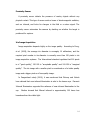
The design is an automated iris recognition system with a hardware that
consists of a webcam, Gizduino microcontroller, NIR LEDs, power supply, and a
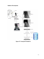
proximity sensor. Figure 3.1 illustrates the conceptual framework of the design.
The proximity sensor sense objects that are in front of its transceiver, in the
design, the face of the person is the target of the proximity sensor. When the
target is within the detecting range of the sensor, the sensor will output a signal
that is treated as an input to the microcontroller, and this will command the
webcam to capture an image. Through proper alignment, this captured image
would be the eye of the subject. The NIR light serves as the illuminations to
acquire iris of the eye visible to the webcam. After the webcam captures the eye,
the image acquisition software produces the iris image that will be sent to the iris
recognition algorithm for analysis.
19
Hardware Development
Figure 3.1 Conceptual Framework
20
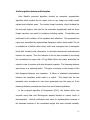
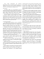
Figure 3.2: Block Diagram
Figure 3.2 represents the block diagram that was implemented to attain the
goals of the design. The automation part is composed of the proximity sensor,
the microcontroller and the image acquisition software. This automation block as
its name implies, automates the capturing of the webcam through the use of the
sensor, that is connected to the microcontroller in which is handled by the image
21
acquisition software. The proximity sensor senses objects within 10cmrange from
its transceiver. The microcontroller used is the Gizduino microcontroller
manufactured and produced by E-Gizmo. The image acquisition software is
developed using MATLAB R2009a. The next part is the Iris Capture block. It
consists of the webcam and the NIR LEDs. The webcam is connected to the
computer through its USB cord. The NIR LEDs are the one responsible for the
visibility of the iris to the webcam. If the image acquisition software tells the
webcam to capture, the webcam will do so and an iris image will be produced.
The final part is the iris recognition algorithm. The iris recognition algorithm
starts with the iris segmentation process. It is based on the circular Hough
transform which is similar to the equation of a circle (X C 2 + Y C 2 = r2). Since the
iris of the eye is ideally shaped like a circle, the Hough transform is used to
determine the properties of geometric objects found in an image like circles, and
lines. Canny edge detection is used to detect edges of shapes. It is developed by
John F. Canny in 1986. Horizontal lines are drawn on the top and bottom eyelid
to separate the iris and two circles are drawn, one for the pupil and the other
one for the iris. The value of the iris radius to be used ranges from 75 to 85
pixels and for the pupil radius ranges from 20 to 60 pixels. After the iris is
segmented, it is normalized. In normalization, the segmented iris is converted to
a rectangular shaped-strip with fixed dimensions. This process uses Daugman‘s
rubber sheet model. The image will then be analyzed using 2D wavelets at
maximum level of 5. After that, a biometric template is produced. Similar to
22
Engr. Panganiban‘s work, the wavelet transform is used to extract the
discriminating information in an iris pattern. Only one mother wavelet is used
which is the Haar because it produced the highest CRR according to Engr.
Panganiban‘s thesis. The template is encoded using the patterns that yielded
during the wavelet decomposition. Then, the algorithm will check if the template
matches another template stored in the database by using its binary form to
compute for the hamming distance of the two templates. This is done by using
the XOR operation. A template can also be added to the database by using MS
SQL queries.
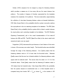
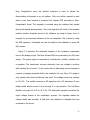
Figure 3.3 describes the schematic diagram of the hardware components
used in the design project. The Near Infrared LEDs are powered by the 5V power
supply. The power supply is composed of a transformer, rectifier, capacitor and
a regulator. The transformer converts electricity from one voltage to another
with minimal loss of power. It only works with an alternating current because it
requires a changing magnetic field to be created in its core. Since 5-V supply is
only needed, step-down transformer was used. The voltage source was reduced
to 12-V AC. The rectifier converts an AC waveform into a DC waveform. It uses
diodes which allows current to flow through it in one direction. The Full-Wave
Rectifier converted 12-V AC to 12-V DC. The electrolytic capacitor smoothen the
ripple voltage formed in the rectification process. The regulator makes the
voltage stable and accurate. A heat sink was attached to dissipate the heat
produced by the circuit.
23
Figure 3.3: Schematic Diagram
24
The Near Infrared LEDs serves as the lighting source. The light produced by
the near-infrared diodes is only visible in the camera and not with the human
eye. It produces less noise in the image when captured than visible light. The
resistors used each have 5-ohms resistance. This was computed using the
formula:
R = (VS - VF) / IF
where VS is the voltage source of 5-V, VF is the voltage drop of 1.5-V and an IF is
a current of 100-mA. The formula would produce a resistance of 35-ohms. But
considering that we are to connect in parallel four rows of 3 NIR LEDs in series,
the resulting resistance value ‗R‘ connected in series with the 3 NIR LEDs on
each row would be 5-ohms.
The proximity sensor detects the presence of nearby objects without any
physical contact. This type of sensor emits a beam of electromagnetic radiation,
such as infrared, and looks for changes in the field or a return signal. This gives
the appropriate signal to the image-capturing software when the subject is in the
right position for iris image acquisition.
The Gizduino microcontroller is a clone of Arduino microcontroller made by
the company E-Gizmo. It has a built-in ATMEGA microcontroller and PL2303 USB
to RS-232 Bridge Controller.
25
Software Development
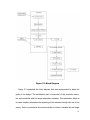
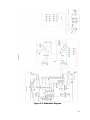
Figure 3.4: System Flowchart
26
Figure 3.4 illustrates the flowchart of the system. First, the system initializes the
camera and the microcontroller settings. Then, it checks whether the Gizduino
microcontroller is connected or not by checking the value of gizduinoPort. While
it is equal to zero, the system will end its process. But while its value is not equal
to zero, meaning the MCU is still connected, it inspects if the person‘s face is
within the correct distance by checking the value of gizduinoPort.digitalRead(8).
If the value is zero, it means that the distance is correct according to the
proximity sensor and the program triggers the camera to capture the iris image.
After capturing the image, the system processes it, extracts the iris feature and
encodes the template into bits. After that, the system compares the encoded
template with all the templates stored in the database. When a match is found,
the program displays a message box telling that the person‘s iris is authenticated
and is registered on the database and then the system prepares for the next
capture by going back to the distance inspection. But when it‘s not found, the
program displays a message box again however telling that it is not found and
it‘s not authenticated. Also, the system asks if the unauthenticated iris template
is to be enrolled in the database or not. If it would be enrolled, then the iris
template and its path are inserted into the database and then the system goes
back to the distance inspection. Else if it‘s not to be enrolled, then the system
just goes back to the distance inspection.
27
Column Name
IrisId
IrisPath
IrisTemplate
IrisDataBankDesign
Data Type
Key Type
Int
PK
varchar(50)
NONE
varchar(MAX)
NONE
Allow Null
No
Yes
Yes
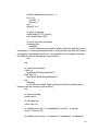
Figure 3.5 Relational Model
The template bits are stored in a database using Microsoft SQL 2005 Express
edition. In Fig. 3.5, the IrisId field is set to auto-increment by 1 and the primary
key. While the IrisPath and IrisTemplate depends on the output of the system
which is inserted to the database.
Prototype Development
The design prototype has both hardware and software components.
The
hardware components are comprised of a 5-V power supply, Near Infrared LEDs,
CMOS webcam, proximity sensor, Gizduino microcontroller and a personal
computer. And for the software, the MS SQL 2005 Express Edition, MATLAB 7.8,
and Arduino compiler are used. The design is assembled in a way that the
subject‘s eye would be captured is aligned with the camera lens with respect to
the time the sensor detects that the subject‘s face is on the specific range, and
sends signal to the microcontroller to automate the camera for capturing the iris
image.
28
Figure 3.6: 5V Power Supply
5V Power Supply
In the hardware part, a 5-V 750-mA power supply is used to power up the
NIR LEDs. It is composed of a transformer, rectifier, capacitor and a regulator.
The transformer used is a step down transformer with a turn‘s ratio of
approximately 18.33 in which it is able to produce a secondary AC voltage of 12V from a primary AC voltage of 220-V. The type of rectifier used is a bridge
rectifier.Four 4N001 diodes are used to build it so that it produces a full-wave
rectification in which the 12-VAC is converted to a 12-VDC. However, this produces
a varying DC output. A 470-uF electrolytic capacitor is used to eliminate this and
produce a small ripple voltage. To produce a 5-V DC output, a 5-V voltage
regulator is used; in this case, LM7805 IC is used. This also makes the voltage
stable and accurate and a heat sink was attached to it in order to dissipate the
heat produced by the circuit.
29
Figure 3.7: NIR LED
NIR LEDs
For the NIR LEDs, a series-parallel circuit connection is used. Considering the
current, each LED has a forward current of 100-mA and the power supply could
only produce 750-mA output. Also taking in to account for the voltage, the
typical forward voltage of each LED which are used is 1.5-V and the power
supply can only produce a 5-V output. Because of these current and voltage
settings, only up to 7 parallel set of LEDs and each set contains 3 IR LEDs
respectively. A resistor should be used in order to protect the LEDs from burning.
In the computation, 5-Ohms resistor is calculated. This value can protect the
LEDs from burning because it can control the current below 100mA. Using the
next lower resistor value would destroy the LEDs.
30
Figure 3.8: Proximity Sensor
Proximity Sensor
The proximity sensor used is an infrared proximity-collision sensor. It is
produced and manufactured by E-Gizmo Electronics and Robotics Shop. It has
two wires for input and one for output. The input wires which are colored red
and green are for the 5V supply and the ground connection, respectively. For its
power, it uses the Gizduino microcontroller board for its 5V source since this
microcontroller could deliver such a voltage output. It uses a TFDU6103 IrDa
transceiver (see datasheets for info). There are two of it in the sensor; one
serves as the receiver and the other as the transmitter. A blockade within 10cm
range will have it output a low signal. This sensor is used to send signal to the
microcontroller for the program to allow the camera to take a picture whenever
the sensor would detect that the person‘s iris to be captured is within the correct
distance. Furthermore, the sensor is composed of capacitors, resistors, LM555
IC, and LM567 IC.
31
Figure 3.9: Gizduino
Gizduino Microcontroller
The Gizduino Microcontroller has 14 digital input/output ports and 8 analog
input/output ports. The output port of the proximity sensor is connected to one
of its digital input/output ports. It also has 3 ground pins, 5-V pin, and 3.3-V pin.
Figure 3.10: Webcam
Webcam
The camera used is the a4tech PK 710mj live messenger 5M Webcam. It is
connected to the USB port of the computer. A manual focused camera was used
so that the correct distance of the person‘s iris to the lens of the camera may be
set specifically in a way the eye of the person would only be captured by the
32
camera, the focus range is set about 4cm. In this case, the image being captured
by the camera is stable in terms of how far the eye is from the camera to
distinguish accurately the iris to be segmented and recognized.
Camera Specification:
Image Sensor: ¼ CMOS, 640x480pixels
Frame Rate: 15fps: @640x480, @600x800, 30fps: @320x240,@160x120
Lens F=2.2, f=4.6mm
View Angle: 65 degree
Focus Range: Manual Focus, 2cm to infinity
Exposure Control: Automatic
Still Image Capture Res.: 2560x2048, 1600x1280, 2000x1600, 1280x960,
600x800, 640x480, 352x288, 320x240, 160x120
Flicker Control: 50 Hz, 60Hz and None
Computer Port USB 2.0 port
33
CHAPTER 4
TESTING, PRESENTATION, AND INTERPRETATION OF DATA
Automated CMOS Camera for iris recognition through proximity sensor focus
on its objective of improving an existing image acquisition of the iris recognition
system developed by Engr. Panganiban and the design‘s automation. In this
chapter, the researchers conduct experiments to identify whether the hardware
and software design meet the criteria for an effective iris recognition system.
Several observations and assessments are provided, together with reliable
measurements or data that will support the researcher‘s remarks.
SENSOR OUTPUT TEST
The proximity sensor automates the system by detecting whether the person
is at the correct distance and position before capturing the subject‘s iris. Further
testing on the proximity sensor was done because there has been a suspected
glitch found on the proximity sensor.
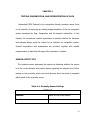
Table 4.1: Proximity Sensor Settings
SETTINGS
Position:
Placed on top of the camera
Input:
Person‘s forehead
34
Table 4.2: Sensor Output Testing
DISTANCE(cm)
Red LED Status (Output)
1
Solid Red Light
2
Solid Red Light
3
Solid Red Light
4
Solid Red Light
5
Flickering Red Light
6
No light
7
No light
8
No light
9
No light
10
No light
As seen in Table 4.2, the correctness of the distance and position was seen on
the red LED‘s intensity with respect to the settings indicated in table 4.1. A solid
red light was seen when an object is 0cm to 4m away from the IrDA. But a
flickering red light was seen when the range is within the range of 4cm to 5cm.
The LED does not produce light when the object is greater than 5cm. Also, these
findings were relevant to the behaviour of the camera. When the red LED has a
solid light, the camera captures every time an object is sensed.
35
IMAGE QUALITY TEST
The performance of the iris recognition system, particularly recognition and
segmentation, and the interoperability are highly dependent in the quality of the
iris image.
Table 4.3: Camera Specifications
Specifications
Image Sensor
Focus Range
CCD Camera
A4tech PK 710mj live
messenger 5M Webcam
CCD image sensor with
CMOS image sensor,
validity pixel of PAL:
640x480pixels
512x528/- 512x492
Manual focus according Manual Focus, 2cm to
infinity (according to user
to user requirement
requirement)
Our group replaced Eng‘r. Panganiban‘s CCD Camera with a CMOS Camera.
The camera must possess excellent imaging performance in order to produce
accurate results. In a CCD (Charge Couple Device) sensor, every pixel‘s charge is
transferred through a very limited number of output nodes to be converted to
voltage, buffered, and sent off-chip as an analog signal. All of the pixel can be
devoted to light capture, and the uniformity of the output is high. In a CMOS
(Complementary Metal Oxide Semiconductor) sensor, each pixel has its own
charge-to-voltage conversion, and the sensor often includes amplifiers, noisecorrection, and digitalization circuits, so that the chip outputs digital bits. With
these, the design complexity increases and the area available for light capture
decreases. The uniformity is lower because each pixel is doing its own
36
conversion. Also, both cameras that were used were manual focus, for the user
to adjust it to their system‘s requirements.
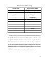
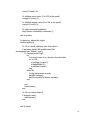
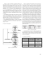
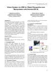
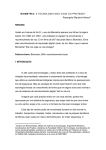
Figure 4.1: Selected iris images from Engr. Panganiban’s system
37
Figure 4.2: Selected iris images from the current system
Table 4.4: Iris Image Quality Assessment
Common Quality Metrics
Blur Motion
Noise in the Iris Image
Brightness
Magnification
Figure 4.1
Blurred Image
With Noise
Dark
Blurred Image
Figure 4.2
Clear Image
Without Noise
Bright
Clear Image
In Table 4.4, it can be observed that the improved design really showed
promising results. The design produced a clear and bright image even though
the image was magnified in the test. The magnification testing was made by
zooming in the images. Also, there was no noise in the iris image.
38
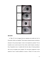
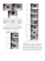
Table 4.5: Enrolled Captured Iris Images
ID
Number
Iris Image
1
2
3
4
5
6
39
7
8
9
10
DATASETS
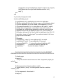
In Table 4.5, the iris images that were captured and enrolled into the Iris
Recognition System are displayed. These images undergone image processing as
discussed in the previous chapter to have its iris template be produced. The iris
templates were encoded using the Haar mother wavelet because according to
Engr. Panganiban‘s work, it resulted with the best values of Hamming distance
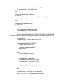
after every iris template were compared. The Inter-class comparisons of Haar
wavelet at Level 4 vertical coefficient is shown on Table 4.6. As seen on the
40
table, the maximum HD value is 0.1538 and the minimum is 0.1060. A zero value
indicates that the iris templates are perfectly matching each other.
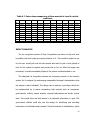
Table 4.6: Inter-class comparisons of Haar wavelet at Level 4 vertical
coefficient
Iris
Id
1
2
3
4
5
6
7
8
9
10
1
2
3
4
5
6
7
8
9
10
0.0000
0.1331
0.1331
0.1268
0.1060
0.1268
0.1227
0.1331
0.1081
0.1206
0.1331
0.0000
0.1331
0.1518
0.1351
0.1268
0.1227
0.1372
0.1372
0.1414
0.1331
0.1331
0.0000
0.1268
0.1351
0.1227
0.1268
0.1081
0.1247
0.1372
0.1268
0.1518
0.1268
0.0000
0.1247
0.1372
0.1206
0.1143
0.1227
0.1060
0.1060
0.1351
0.1351
0.1247
0.0000
0.1123
0.1538
0.1435
0.1351
0.1310
0.1268
0.1268
0.1227
0.1372
0.1123
0.0000
0.1289
0.1393
0.0977
0.1268
0.1227
0.1227
0.1268
0.1206
0.1538
0.1289
0.0000
0.1227
0.1102
0.1185
0.1331
0.1372
0.1081
0.1143
0.1435
0.1393
0.1227
0.0000
0.1123
0.1206
0.1081
0.1372
0.1247
0.1227
0.1351
0.0977
0.1102
0.1123
0.0000
0.1206
0.1206
0.1414
0.1372
0.1060
0.1310
0.1268
0.1185
0.1206
0.1206
0.0000
It is observable that when the Hamming distance value is greater than or equal
to 0.1060, the iris templates do not match.
In table 4.6, the Intra-class
comparisons of Haar Wavelet at level 4 vertical coefficient shows that when the
HD value is less than 0.1060, the iris template are from the same individual.
Using the formula for the degrees of freedom:
Where p is the mean which is equal to 0.1261 and the σ is the standard
deviation which is equal to 0.03954, the number of degrees of freedom is 80.
According to statistics, this is the number of degrees of freedom that the values
in this case, the HD values are free to vary.
41
Table 4.7: Intra-class comparisons of Haar wavelet at Level 4 vertical
coefficient
Iris
Id
1
2
3
4
5
6
7
8
9
10
1
2
3
4
5
6
7
8
9
10
0.0811
0.1310
0.1310
0.1164
0.1247
0.1372
0.1164
0.1310
0.1102
0.1019
0.1351
0.0603
0.1310
0.1331
0.1206
0.1206
0.1164
0.1518
0.1435
0.1227
0.1310
0.1019
0.0686
0.1497
0.1455
0.1081
0.1164
0.1268
0.1185
0.1476
0.1060
0.1185
0.1351
0.0956
0.1247
0.1289
0.1080
0.1310
0.1019
0.1143
0.1123
0.1331
0.1372
0.1268
0.0852
0.1185
0.1310
0.1580
0.1289
0.1455
0.1247
0.1123
0.1247
0.1393
0.1060
0.0520
0.1393
0.1060
0.1123
0.1247
0.1227
0.1268
0.1476
0.1247
0.1372
0.1372
0.0873
0.1227
0.1435
0.0977
0.1289
0.1289
0.1081
0.1310
0.1351
0.1227
0.1185
0.0748
0.1164
0.1247
0.1185
0.1435
0.1227
0.1123
0.1206
0.0915
0.1164
0.1227
0.0561
0.1143
0.1227
0.1227
0.1019
0.104
0.1518
0.1372
0.1206
0.1227
0.1143
0.0977
IMPACT ANALYSIS
The iris recognition system of Engr. Panganiban was taken to the next level
by adding real time image processing features to it. This would be easier to use
for the user would just look into the camera and wait for just a short period of
time for the system to capture and process his or her iris. After the image was
processed, it would immediately display if the person is authenticated or not.
The designed iris recognition showed an increasing promise on the security
system for it analyses the unchanging measurable biological characteristics that
are unique to each individual. The design can be used as a prototype which can
be implemented by in places demanding high security such as companies,
governments, military, banks, airports, research laboratories and border control
area. This would allow and limit access to a particular information or area. The
government officials could also use this design for identifying and recording
information of individuals and criminals. Physical methods of identification, which
42
includes anything requiring a password, personal identification number or key for
building access or the like, are easily hacked or stolen but human iris cannot be
stolen. This technology addresses the problems of both password management
and fraud.
43
CHAPTER 5
CONCLUSION AND RECOMMENDATION
CONCLUSION
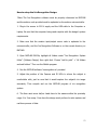
Based from the results obtained, the design was proven sufficient for iris
recognition. The camera used is a manual focus- CMOS camera. In a
Complementary Metal Oxide Semiconductor sensor, each pixel has its own
charge-to-voltage conversion, and the sensor often includes amplifiers, noisecorrection, and digitalization circuits, so that the chip outputs digital bits. With
these, the design complexity increases and the area available for light capture
decreases. The correct positioning of the webcam, NIR LEDs and sensor
produced a clearer and brighter iris image which really improves the
performance of the iris recognition system. The NIR LEDs must be attached
circular to the webcam so that noise that would be produced in the iris would be
lessened. The light of the NIR LEDs would be directed to the pupil. Since the
light reflection will be located in the pupil, it would not affect the iris
segmentation and that the iris template. The case of the camera also lessens the
noise since it blocks other factors that might affect the iris image and results.
The proximity sensor has a delay of 5 seconds before it sends signal for the
webcam to capture the iris image. There is a delay so that the user can position
his or her eye properly to the device.
44
Also, the results showed that when the Hamming distance value is greater
than or equal to 0.1060, the iris templates do not match. The Intra-class
comparison of Haar Wavelet at level 4 vertical coefficient shows that when the
HD value is less than 0.1060, the iris templates are from the same individual.
From the results of the Hamming Distance in inter-class comparison, the
Degrees of Freedom (DoF) computed is 80, which is higher than of Engr.
Panganiban‘s work which is equal to 50. This shows that the comparison of iris
templates in our design is more accurate.
45
RECOMMENDATION
Although the obtained results proved that the design is sufficient for iris
recognition, the following are still recommended for the improvement of the
system‘s performance:
1. The proximity sensor may be replaced by an algorithm such as pattern
recognition that will allow the software to capture the iris image once a
circular shape is near the camera.
2. The digital camera can be converted to an Infrared Camera which would
replace the webcam and NIR LEDs.
3. Artificial Intelligence, such as Fuzzy Logic, can be applied to the system to
improve the performance of the Iris recognition system.
4. Embedding the Iris recognition system, its hardware and software into one
device can be done to have the speed of the system independent on the
speed of the computer used and could also be portable.
46
REFERENCES
Addison, P. (2002). The Illustrated Wavelet Transform Handbook, Institute of
Physics.
Bradley J., Brislawn, C., and Hopper, T. (1993). The FBI Wavelet/Scalar
Quantization Standard for Gray-scale Fingerprint Image Compression. Tech.
Report LA-UR-93-1659, Los Alamos Nat'l Lab, Los Alamos, N.M.
Boles, W.W. and Boashash, B.A. (1998). A human identification technique using
images of the iris and wavelet transform,‖ IEEE trans. on signal processing, vol.
46, issue 4.
Canny, J. (1986). A Computational Approach To Edge Detection, IEEE Trans.
Pattern Analysis and Machine Intelligence, 8:679–714.
Cohn, J. (2006). Keeping an Eye on School Security: The Iris Recognition Project
in New Jersey Schools. NIJ Journal, no. 254.
Huifang, H. and Guangshu, H. (2005). Iris recognition based on adjustable scale
wavelet transform. Proceedings of the 2005 IEEE.
47
Kong, W. and Zhang, D. (2001). Accurate iris segmentation based on novel
reflection and eyelash detection model. Proceedings of 2001 International
Symposium on Intelligent Multimedia, Video and Speech Processing, Hong Kong.
Makram Nabti and Bouridane (2007). An effective iris recognition system based
on wavelet maxima and Gabor filter bank. IEEE trans. on iris recognition.
Masek, L. (2003). Recognition of Human Iris Patterns for Biometric Identification.
Narote et al. (2007). An iris recognition based on dual tree complex wavelet
transform. IEEE trans. on iris recognition.
Panganiban, A. (2009). CCD Camera with Near-Infrared Illumination for Iris
Recognition System.
(2010).
Implementation
of
Wavelet
Algorithm
for
Iris
Recognition System.
48
APPENDIX A
Operation‘s Manual
I.
System Requirements
CPU:
Intel® Core™ i7
Memory:
4.00 GB
Operating System:
Software:
II.
Windows 7
MATLAB R2009a
Installation Procedure
1. MATLAB R2009a installation (Recommended):
1.1
Load the MATLAB R2009a installer; it should automatically start the
installation program whereby the first splash screen could be seen.
1.2
Agree to the Mathworks license, and then press Next.
1.3
Choose the ‗Typical‘ installation, and then press Next.
1.4
Choose the location of the installation, and then press Next.
1.5
If the location doesn‘t exist, you will be prompted to create it and
MATLAB will ask you for the location on where the files will be installed.
1.6
Confirm the installation settings by pressing ‗Install‘
1.7
MATLAB will now install, this may take several minutes
49
1.8
Close to the end of the installation, you will be asked if you want to
set up some file associations. Choose ‗Yes to All‘.
1.9
After the installation has completed, you will be asked for the serial
key for the software license. Enter the serial key and press Next.
1.10
MATLAB will initially make an internet connection to Mathworks.
Answer ‗Yes‘ when asked if you are a student. Then press Next.
1.11
Enter the serial key and your email address. Then press Next.
1.12
Continue with the rest of the registration process until the
installation is complete.
2. Arduino Compiler installation:
(For Windows)
2.1. Get an Arduino board, and connect it to your computer with a USB
cable.
2.2. Download the
Arduino environment on its
official website.
(http://arduino.cc/en/Main/Software)
2.3. Install the drivers
2.3.1. Wait for Windows to begin its driver installation process. After a few
moments, the process will fail, despite its best efforts.
2.3.2. Click on the Start Menu, and open up the Control Panel.
50
2.3.3. While in the Control panel, navigate to System and Security. Next,
click on System. Once the System window is up, open the Device
Manager.
2.3.4. Look under Ports (COM & LPT). There should be an open port
named ―Arduino UNO (COMxx)‖.
2.3.5. Right click on the ―Arduino UNO (COMxx)‖ port and choose the
―Update Driver Software‖ option.
2.3.6. Next, choose the ―Browse my computer for Driver software‖ option.
2.3.7. Finally, navigate to and select the UNO‘s driver file, named
―ArduinoUNO.inf‖, located in the ‗‖Drivers‖ folder of the Arduino Software
download (not the ―FTDI USB Drivers‖ sub-directory).
2.3.8. Windows will complete the driver installation from there.
III.
User’s Manual
How to use the Gizduino microcontroller and software:
1. Connect the Gizduino microcontroller to the USB port of the computer.
2. Open the Arduino Compiler.
3. From the Menu Bar, select Tools then choose Serial Port and select the
designated port where the microcontroller is connected.
51
4. On the Arduino workspace, enter the arduino input/output server code that
is listed on Appendix C.
5. Compile the code by pressing Verify button to check for errors before
uploading it to the microcontroller.
6. To upload the code to the microcontroller, press the Upload button.
7. Wait until the uploading is finished; A message ―Uploading Successful‖ will be
displayed.
How to use the MATLAB iris recognition software:
1. Open a MATLAB workspace.
2. In the directory icon, browse the folder where the source code is located, in
this case the programs are stored under a folder named ―Design Project‖.
3. In the command directory area, make sure that all files and folders are
properly referenced. *Note: highlight all folders under the ―Design Project‖ folder
then right click. Choose ―add to path‖ > ―all folders and sub folders‖.
4. In the current directory, right click on the ‗irisrecognition.m‘ program and
choose ―Run File‖ to run this program.
52
How to setup the Iris Recognition Design:
*Note: The Iris Recognition software must be properly referenced on MATLAB
and the arduino code provided must be uploaded on the arduino microcontroller.
1. Plug-in the source to 220-V supply and the USB cable to the Computer or
Laptop. Be sure that the computer being used complies with the design‘s system
requirements.
2. Make sure that the arduino input/output server code is uploaded to the
microcontroller, and the Iris Recognition Software is on the current directory on
MATLAB.
3. Open MATLAB R2009a, highlight all folders under ―Iris Recognition System
folder‖ (Software Design) then right click. Choose ―add to path‖ > ―all folders
and sub folders‖. Then run the Matlab program.
4. Run the MATLAB software ‗irisrecognition.m‘ provided.
5. Adjust the position of the Camera and IR LEDs to where the subject is
comfortable with; just be sure that it would capture the subject‘s iris image
accurately. Then compile and run the MATLAB program of iris recognition
system.
6. The User must move his/her head close to the camera within the proximity
range 4 to 5-cm away. From here the design must perform its auto-capture and
real-time process of data.
53
7. If the iris image captured isn‘t within the authenticated list on the database,
the user will be asked to whether or not enrol the iris image. Otherwise the
program will simply display ―unauthenticated‖ iris image pattern.
8. After the authentication the program will go back to its status of autocapturing an iris image.
9. To terminate, simply exit the MATLAB program.
IV. Troubleshooting Guides and Procedures
1. If there is a problem on the Arduino Connection on MATLAB
a) Upload the adiosrv.pde on the Gizduino
b) Check if the COM PORT where the Gizduino is connected is the same on
the SerialPort() definition on MATLAB
2. If the image is blurred, check and adjust the focus of the camera. Twist its
lens to have the desired focus.
3. Uploading Errors on Gizduino
a) Check the syntax for errors.
b) Consult the website, www.arduino.cc, for more information.
4. Unknown MATLAB function
a) Check if the program files are located at the current directory window of
MATLAB.
54
b) If the files are already the current directory of MATLAB, select all files and
right click then add to path all the folders and subfolders.
5. If there are many cameras connected and installed on the laptop, check the
image acquisition toolbox of MATLAB and select the adaptor name and device ID
of the desired camera to be used.
6. There is no light emitted by the LEDs
a) Make sure that the polarity on the source to LED connection is correct.
b) Check the proper connection of the LEDs in series and parallel.
c) Plug the power supply.
V. Error Definitions
MATLAB:
1. Error in using videoinput in MATLAB – The camera device is not detected by
MATLAB or its DEVICEID or adapter name is invalid.
2. Error at segmentiris.m – There are no detectable circular patterns.
3. COM PORT unavailable- There is no devices connected on the particular Serial
COM port
4. Function or CD diagnostics or directory not found- make sure that the current
directory in MATLAB is the one where the .m files are placed
55
Arduino Compiler:
1. Error Compiling- Check the syntax for errors
2. Serial Port not found- The Gizduino microcontroller is connected to a different
Serial Port or there is nothing connected.
56
APPENDIX B
Pictures of Prototype
57
APPENDIX C
Program Listing
Arduino.m
classdef arduino < handle
% This class defines an "arduino" object
% Giampiero Campa, Aug 2010, Copyright 2009 The MathWorks, Inc.
properties (SetAccess=private,GetAccess=private)
aser % Serial Connection
end
methods
% constructor, connects to the board and creates an arduino object
function a=arduino(comPort)
% Add target directories and save the updated path
addpath(fullfile(pwd));
savepath
% check nargin
if nargin<1,
comPort='DEMO';
disp('Note: a DEMO connection will be created');
disp('Use a the com port, e.g. ''COM5'' as input argument to connect
to the real board');
end
% check port
if ~ischar(comPort),
error('The input argument must be a string, e.g. ''COM8'' ');
end
% check if we are already connected
if isa(a.aser,'serial') && isvalid(a.aser) &&
strcmpi(get(a.aser,'Status'),'open'),
disp(['It looks like Arduino is already connected to port ' comPort ]);
disp('Delete the object to force disconnection');
disp('before attempting a connection to a different port.');
58
return;
end
% check whether serial port is currently used by MATLAB
if ~isempty(instrfind({'Port'},{comPort})),
disp(['The port ' comPort ' is already used by MATLAB']);
disp(['If you are sure that Arduino is connected to ' comPort]);
disp('then delete the object to disconnect and execute:');
disp([' delete(instrfind({''Port''},{''' comPort '''}))']);
disp('to delete the port before attempting another connection');
error(['Port ' comPort ' already used by MATLAB']);
end
% define serial object
a.aser=serial(comPort);
% connection
if strcmpi(get(a.aser,'Port'),'DEMO'),
% handle demo mode
fprintf(1,'Demo mode connection ..');
for i=1:4,
fprintf(1,'.');
pause(1);
end
fprintf(1,'\n');
pause(1);
% chk is 1 or 2 depending on the script running on the board
chk=round(1+rand);
else
% actual connection
% open port
try
fopen(a.aser);
catch ME,
disp(ME.message)
delete(a);
error(['Could not open port: ' comPort]);
end
% it takes several seconds before any operation could be attempted
59
fprintf(1,'Attempting connection ..');
for i=1:4,
fprintf(1,'.');
pause(1);
end
fprintf(1,'\n');
% query script type
fwrite(a.aser,[57 57],'uchar');
chk=fscanf(a.aser,'%d');
% exit if there was no answer
if isempty(chk)
delete(a);
error('Connection unsuccessful, please make sure that the Arduino
is powered on, running either adiosrv.pde or mororsrv.pde, and that the board is
connected to the indicated serial port. You might also try to unplug and re-plug
the USB cable before attempting a reconnection.');
end
end
% check returned value
if chk==1,
disp('Basic I/O Script detected !');
elseif chk==2,
disp('Motor Shield Script detected !');
else
delete(a);
error('Unknown Script. Please make sure that either adiosrv.pde or
motorsrv.pde are running on the Arduino');
end
% sets a.mots flag
a.mots=chk-1;
% set a.aser tag
a.aser.Tag='ok';
% initialize pin vector (-1 is unassigned, 0 is input, 1 is output)
a.pins=-1*ones(1,19);
% initialize servo vector (-1 is unknown, 0 is detached, 1 is attached)
60
a.srvs=0*ones(1,2);
% initialize motor vector (0 to 255 is the speed)
a.mspd=0*ones(1,4);
% initialize stepper vector (0 to 255 is the speed)
a.sspd=0*ones(1,2);
% notify successful installation
disp('Arduino successfully connected !');
end % arduino
% distructor, deletes the object
function delete(a)
% if it is a serial, valid and open then close it
if isa(a.aser,'serial') && isvalid(a.aser) &&
strcmpi(get(a.aser,'Status'),'open'),
if ~isempty(a.aser.Tag),
try
% trying to leave it in a known unharmful state
for i=2:19,
a.pinMode(i,'output');
a.digitalWrite(i,0);
a.pinMode(i,'input');
end
catch ME
% disp but proceed anyway
disp(ME.message);
disp('Proceeding to deletion anyway');
end
end
fclose(a.aser);
end
% if it's an object delete it
if isobject(a.aser),
delete(a.aser);
end
end % delete
61
% disp, displays the object
function disp(a) % display
if isvalid(a),
if isa(a.aser,'serial') && isvalid(a.aser),
disp(['<a href="matlab:help arduino">arduino</a> object
connected to ' a.aser.port ' port']);
if a.mots==1,
disp('Motor Shield Server running on the arduino board');
disp(' ');
a.servoStatus
a.motorSpeed
a.stepperSpeed
disp(' ');
disp('Servo Methods: <a href="matlab:help
servoStatus">servoStatus</a> <a href="matlab:help
servoAttach">servoAttach</a> <a href="matlab:help
servoDetach">servoDetach</a> <a href="matlab:help
servoRead">servoRead</a> <a href="matlab:help
servoWrite">servoWrite</a>');
disp('DC Motors and Stepper Methods: <a href="matlab:help
motorSpeed">motorSpeed</a> <a href="matlab:help
motorRun">motorRun</a> <a href="matlab:help
stepperSpeed">stepperSpeed</a> <a href="matlab:help
stepperStep">stepperStep</a>');
else
disp('IO Server running on the arduino board');
disp(' ');
a.pinMode
disp(' ');
disp('Pin IO Methods: <a href="matlab:help
pinMode">pinMode</a> <a href="matlab:help digitalRead">digitalRead</a>
<a href="matlab:help digitalWrite">digitalWrite</a> <a href="matlab:help
analogRead">analogRead</a> <a href="matlab:help
analogWrite">analogWrite</a>');
end
disp(' ');
else
disp('<a href="matlab:help arduino">arduino</a> object
connected to an invalid serial port');
disp('Please delete the arduino object');
disp(' ');
end
else
62
disp('Invalid <a href="matlab:help arduino">arduino</a> object');
disp('Please clear the object and instantiate another one');
disp(' ');
end
end
% pin mode, changes pin mode
function pinMode(a,pin,str)
%
%
%
%
%
%
%
%
%
%
%
%
%
%
%
%
%
%
a.pinMode(pin,str); specifies the pin mode of a digital pins.
The first argument before the function name, a, is the arduino object.
The first argument, pin, is the number of the digital pin (2 to 19).
The second argument, str, is a string that can be 'input' or 'output',
Called with one argument, as a.pin(pin) it returns the mode of
the digital pin, called without arguments, prints the mode of all the
digital pins. Note that the digital pins from 0 to 13 are located on
the upper right part of the board, while the digital pins from 14 to 19
are better known as "analog input" pins and are located in the lower
right corner of the board.
Examples:
a.pinMode(11,'output') % sets digital pin #11 as output
a.pinMode(10,'input') % sets digital pin #10 as input
val=a.pinMode(10);
% returns the status of digital pin #10
a.pinMode(5);
% prints the status of digital pin #5
a.pinMode;
% prints the status of all pins
%%%%%%%%%%%%%%%%%%%%%%%%% ARGUMENT
CHECKING %%%%%%%%%%%%%%%%%%%%%%%%%%%%%%%
% check nargin
if nargin>3,
error('This function cannot have more than 3 arguments, object, pin
and str');
end
% first argument must be the arduino variable
if ~isa(a,'arduino'), error('The first argument must be an arduino
variable'); end
% if pin argument is there check it
if nargin>1,
63
errstr=arduino.checknum(pin,'pin number',2:19);
if ~isempty(errstr), error(errstr); end
end
% if str argument is there check it
if nargin>2,
errstr=arduino.checkstr(str,'pin mode',{'input','output'});
if ~isempty(errstr), error(errstr); end
end
% perform the requested action
if nargin==3,
% check a.aser for validity
errstr=arduino.checkser(a.aser,'valid');
if ~isempty(errstr), error(errstr); end
%%%%%%%%%%%%%%%%%%%%%%%%% CHANGE PIN
MODE %%%%%%%%%%%%%%%%%%%%%%%%%%%%%%%%%
% assign value
if lower(str(1))=='o', val=1; else val=0; end
if strcmpi(get(a.aser,'Port'),'DEMO'),
% handle demo mode here
% average digital output delay
pause(0.0087);
else
% do the actual action here
% check a.aser for openness
errstr=arduino.checkser(a.aser,'open');
if ~isempty(errstr), error(errstr); end
% send mode, pin and value
fwrite(a.aser,[48 97+pin 48+val],'uchar');
end
% detach servo 1 or 2 if pins 10 or 9 are used
if pin==10 || pin==9, a.servoDetach(11-pin); end
64
% store 0 for input and 1 for output
a.pins(pin)=val;
elseif nargin==2,
% print pin mode for the requested pin
mode={'UNASSIGNED','set as INPUT','set as OUTPUT'};
disp(['Digital Pin ' num2str(pin) ' is currently ' mode{2+a.pins(pin)}]);
else
% print pin mode for each pin
mode={'UNASSIGNED','set as INPUT','set as OUTPUT'};
for i=2:19;
disp(['Digital Pin ' num2str(i,'%02d') ' is currently '
mode{2+a.pins(i)}]);
end
end
end % pinmode
% digital read
function val=digitalRead(a,pin)
%
%
%
%
val=a.digitalRead(pin); performs digital input on a given arduino pin.
The first argument before the function name, a, is the arduino object.
The argument pin, is the number of the digital pin (2 to 19)
where the digital input needs to be performed. Note that the digital
pins
% from 0 to 13 are located on the upper right part of the board, while
the
%
%
%
%
%
%
digital pins from 14 to 19 are better known as "analog input" pins and
are located in the lower right corner of the board.
Example:
val=a.digitalRead(4); % reads pin #4
%%%%%%%%%%%%%%%%%%%%%%%%% ARGUMENT
CHECKING %%%%%%%%%%%%%%%%%%%%%%%%%%%%%%%
65
% check nargin
if nargin~=2,
error('Function must have the "pin" argument');
end
% first argument must be the arduino variable
if ~isa(a,'arduino'), error('The first argument must be an arduino
variable'); end
% check pin
errstr=arduino.checknum(pin,'pin number',2:19);
if ~isempty(errstr), error(errstr); end
% check a.aser for validity
errstr=arduino.checkser(a.aser,'valid');
if ~isempty(errstr), error(errstr); end
%%%%%%%%%%%%%%%%%%%%%%%%% PERFORM
DIGITAL INPUT %%%%%%%%%%%%%%%%%%%%%%%%%%%
if strcmpi(get(a.aser,'Port'),'DEMO'),
% handle demo mode
% average digital input delay
pause(0.0247);
% output 0 or 1 randomly
val=round(rand);
else
% check a.aser for openness
errstr=arduino.checkser(a.aser,'open');
if ~isempty(errstr), error(errstr); end
% send mode and pin
fwrite(a.aser,[49 97+pin],'uchar');
% get value
val=fscanf(a.aser,'%d');
end
66
end % digitalread
% digital write
function digitalWrite(a,pin,val)
%
%
%
%
%
%
part
a.digitalWrite(pin,val); performs digital output on a given pin.
The first argument before the function name, a, is the arduino object.
The second argument, pin, is the number of the digital pin (2 to 19)
where the digital output needs to be performed.
The third argument, val, is the value (either 0 or 1) for the output
Note that the digital pins from 0 to 13 are located on the upper right
% of the board, while the digital pins from 14 to 19 are better known as
% "analog input" pins and are located in the lower right corner of the
board.
%
% Examples:
% a.digitalWrite(13,1); % sets pin #13 high
% a.digitalWrite(13,0); % sets pin #13 low
%
%%%%%%%%%%%%%%%%%%%%%%%%% ARGUMENT
CHECKING %%%%%%%%%%%%%%%%%%%%%%%%%%%%%%%
% check nargin
if nargin~=3,
error('Function must have the "pin" and "val" arguments');
end
% first argument must be the arduino variable
if ~isa(a,'arduino'), error('The first argument must be an arduino
variable'); end
% check pin
errstr=arduino.checknum(pin,'pin number',2:19);
if ~isempty(errstr), error(errstr); end
% check val
errstr=arduino.checknum(val,'value',0:1);
if ~isempty(errstr), error(errstr); end
% pin should be configured as output
if a.pins(pin)~=1,
67
warning('MATLAB:Arduino:digitalWrite',['If digital pin ' num2str(pin) '
is set as input, digital output takes place only after using a.pinMode('
num2str(pin) ',''output''); ']);
end
% check a.aser for validity
errstr=arduino.checkser(a.aser,'valid');
if ~isempty(errstr), error(errstr); end
%%%%%%%%%%%%%%%%%%%%%%%%% PERFORM
DIGITAL OUTPUT %%%%%%%%%%%%%%%%%%%%%%%%%%
if strcmpi(get(a.aser,'Port'),'DEMO'),
% handle demo mode
% average digital output delay
pause(0.0087);
else
% check a.aser for openness
errstr=arduino.checkser(a.aser,'open');
if ~isempty(errstr), error(errstr); end
% send mode, pin and value
fwrite(a.aser,[50 97+pin 48+val],'uchar');
end
end % digitalwrite
% analog read
function val=analogRead(a,pin)
pin.
to 5)
% val=a.analogRead(pin); Performs analog input on a given arduino
% The first argument before the function name, a, is the arduino object.
% The second argument, pin, is the number of the analog input pin (0
% where the analog input needs to be performed. The returned value,
val,
volts,
% ranges from 0 to 1023, with 0 corresponding to an input voltage of 0
68
%
%
%
%
%
analog
and 1023 to a value of 5 volts. Therefore the resolution is .0049 volts
(4.9 mV) per unit.
Note that the analog input pins 0 to 5 are also known as digital pins
from 14 to 19, and are located on the lower right corner of the board.
Specifically, analog input pin 0 corresponds to digital pin 14, and
% input pin 5 corresponds to digital pin 19. Performing analog input
does
% not affect the digital state (high, low, digital input) of the pin.
%
% Example:
% val=a.analogRead(0); % reads analog input pin # 0
%
%%%%%%%%%%%%%%%%%%%%%%%%% ARGUMENT
CHECKING %%%%%%%%%%%%%%%%%%%%%%%%%%%%%%%
% check nargin
if nargin~=2,
error('Function must have the "pin" argument');
end
% first argument must be the arduino variable
if ~isa(a,'arduino'), error('The first argument must be an arduino
variable'); end
% check pin
errstr=arduino.checknum(pin,'analog input pin number',0:5);
if ~isempty(errstr), error(errstr); end
% check a.aser for validity
errstr=arduino.checkser(a.aser,'valid');
if ~isempty(errstr), error(errstr); end
%%%%%%%%%%%%%%%%%%%%%%%%% PERFORM
ANALOG INPUT %%%%%%%%%%%%%%%%%%%%%%%%%%%%
if strcmpi(get(a.aser,'Port'),'DEMO'),
% handle demo mode
% average analog input delay
pause(0.0267);
69
% output a random value between 0 and 1023
val=round(1023*rand);
else
% check a.aser for openness
errstr=arduino.checkser(a.aser,'open');
if ~isempty(errstr), error(errstr); end
% send mode and pin
fwrite(a.aser,[51 97+pin],'uchar');
% get value
val=fscanf(a.aser,'%d');
end
end % analogread
% function analog write
function analogWrite(a,pin,val)
% a.analogWrite(pin,val); Performs analog output on a given arduino
pin.
analog
% The first argument before the function name, a, is the arduino object.
% The first argument, pin, is the number of the DIGITAL pin where the
% (PWM) output needs to be performed. Allowed pins for AO are
3,5,6,9,10,11
% The second argument, val, is the value from 0 to 255 for the level of
% analog output. Note that the digital pins from 0 to 13 are located on
the
% upper right part of the board.
%
% Examples:
% a.analogWrite(11,90); % sets pin #11 to 90/255
% a.analogWrite(3,10); % sets pin #3 to 10/255
%
%%%%%%%%%%%%%%%%%%%%%%%%% ARGUMENT
CHECKING %%%%%%%%%%%%%%%%%%%%%%%%%%%%%%%
% check nargin
if nargin~=3,
70
error('Function must have the "pin" and "val" arguments');
end
% first argument must be the arduino variable
if ~isa(a,'arduino'), error('The first argument must be an arduino
variable'); end
% check pin
errstr=arduino.checknum(pin,'pwm pin number',[3 5 6 9 10 11]);
if ~isempty(errstr), error(errstr); end
% check val
errstr=arduino.checknum(val,'analog output level',0:255);
if ~isempty(errstr), error(errstr); end
% pin should be configured as output
if a.pins(pin)~=1,
warning('MATLAB:Arduino:analogWrite',['If digital pin ' num2str(pin) '
is set as input, pwm output takes place only after using a.pinMode('
num2str(pin) ',''output''); ']);
end
% check a.aser for validity
errstr=arduino.checkser(a.aser,'valid');
if ~isempty(errstr), error(errstr); end
%%%%%%%%%%%%%%%%%%%%%%%%% PERFORM
ANALOG OUTPUT %%%%%%%%%%%%%%%%%%%%%%%%%%%
if strcmpi(get(a.aser,'Port'),'DEMO'),
% handle demo mode
% average analog output delay
pause(0.0088);
else
% check a.aser for openness
errstr=arduino.checkser(a.aser,'open');
if ~isempty(errstr), error(errstr); end
% send mode, pin and value
fwrite(a.aser,[52 97+pin val],'uchar');
71
end
end % analogwrite
end % methods
methods (Static) % static methods
function errstr=checknum(num,description,allowed)
%
argument.
%
%
%
%
%
%
errstr=arduino.checknum(num,description,allowed); Checks numeric
This function checks the first argument, num, described in the string
given as a second argument, to make sure that it is real, scalar,
and that it is equal to one of the entries of the vector of allowed
values given as a third argument. If the check is successful then the
returned argument is empty, otherwise it is a string specifying
the type of error.
% preliminary: check nargin
if nargin~=3,
error('checknum needs 3 arguments, please read the help');
end
% preliminary: check description
if isempty(description) || ~ischar(description)
error('checknum second argument must be a string');
end
% preliminary: check allowed
if isempty(allowed) || ~isnumeric(allowed)
error('checknum third argument must be a numeric vector');
end
% initialize error string
errstr=[];
% check num for type
if ~isnumeric(num),
errstr=['The ' description ' must be numeric'];
return
72
end
% check num for size
if numel(num)~=1,
errstr=['The ' description ' must be a scalar'];
return
end
% check num for realness
if ~isreal(num),
errstr=['The ' description ' must be a real value'];
return
end
% check num against allowed values
if ~any(allowed==num),
% form right error string
if numel(allowed)==1,
errstr=['Unallowed value for ' description ', the value must
exactly ' num2str(allowed(1))];
elseif numel(allowed)==2,
errstr=['Unallowed value for ' description ', the value must
either ' num2str(allowed(1)) ' or ' num2str(allowed(2))];
elseif max(diff(allowed))==1,
errstr=['Unallowed value for ' description ', the value must
integer going from ' num2str(allowed(1)) ' to ' num2str(allowed(end))];
else
errstr=['Unallowed value for ' description ', the value must
of the following: ' mat2str(allowed)];
end
be
be
be an
be one
end
end % checknum
function errstr=checkstr(str,description,allowed)
%
argument.
%
%
%
errstr=arduino.checkstr(str,description,allowed); Checks string
This function checks the first argument, str, described in the string
given as a second argument, to make sure that it is a string, and that
its first character is equal to one of the entries in the cell of
73
% allowed characters given as a third argument. If the check is
successful
% then the returned argument is empty, otherwise it is a string
specifying
% the type of error.
% preliminary: check nargin
if nargin~=3,
error('checkstr needs 3 arguments, please read the help');
end
% preliminary: check description
if isempty(description) || ~ischar(description)
error('checknum second argument must be a string');
end
% preliminary: check allowed
if ~iscell(allowed) || numel(allowed)<2,
error('checknum third argument must be a cell with at least 2
entries');
end
% initialize error string
errstr=[];
% check string for type
if ~ischar(str),
errstr=['The ' description ' argument must be a string'];
return
end
% check string for size
if numel(str)<1,
errstr=['The ' description ' argument cannot be empty'];
return
end
% check str against allowed values
if ~any(strcmpi(str,allowed)),
% make sure this is a hozizontal vector
allowed=allowed(:)';
% add a comma at the end of each value
74
for i=1:length(allowed)-1,
allowed{i}=['''' allowed{i} ''', '];
end
% form error string
errstr=['Unallowed value for ' description ', the value must be either: '
allowed{1:end-1} 'or ''' allowed{end} ''''];
return
end
end % checkstr
function errstr=checkser(ser,chk)
%
%
%
%
%
%
errstr=arduino.checkser(ser,chk); Checks serial connection argument.
This function checks the first argument, ser, to make sure that either:
1) it is a valid serial connection (if the second argument is 'valid')
3) it is open (if the second argument is 'open')
If the check is successful then the returned argument is empty,
otherwise it is a string specifying the type of error.
% preliminary: check nargin
if nargin~=2,
error('checkser needs two arguments, please read the help');
end
% initialize error string
errstr=[];
% check serial connection
switch lower(chk),
case 'valid',
% make sure is a serial port
if ~isa(ser,'serial'),
disp('Arduino is not connected, please re-create the object
before using this function.');
errstr='Arduino not connected';
return
end
% make sure is valid
if ~isvalid(ser),
75
disp('Serial connection invalid, please recreate the object to
reconnect to a serial port.');
errstr='Serial connection invalid';
return
end
case 'open',
% check openness
if ~strcmpi(get(ser,'Status'),'open'),
disp('Serial connection not opened, please recreate the object to
reconnect to a serial port.');
errstr='Serial connection not opened';
return
end
otherwise
% complain
error('second argument must be either ''valid'' or ''open''');
end
end % chackser
end % static methods
end % class def
irisrecognition.m
function varargout = irisrecognition(varargin)
% Begin initialization code - DO NOT EDIT
gui_Singleton = 1;
gui_State = struct('gui_Name',
mfilename, ...
'gui_Singleton', gui_Singleton, ...
'gui_OpeningFcn', @irisrecognition_OpeningFcn, ...
'gui_OutputFcn', @irisrecognition_OutputFcn, ...
'gui_LayoutFcn', [] , ...
'gui_Callback', []);
if nargin && ischar(varargin{1})
76
gui_State.gui_Callback = str2func(varargin{1});
end
if nargout
[varargout{1:nargout}] = gui_mainfcn(gui_State, varargin{:});
else
gui_mainfcn(gui_State, varargin{:});
end
% End initialization code - DO NOT EDIT
% --- Executes just before untitled is made visible.
function irisrecognition_OpeningFcn(hObject, eventdata, handles, varargin)
%setup webcam
%vidobj = videoinput('winvideo',1,'YUY2_640X480');
%set(handles.statusLbl,'String','Connecting to camera');
vidobj = videoinput('winvideo',3,'RGB24_640X480');
axes(handles.CameraAxes);
videoRes = get(vidobj, 'VideoResolution');
numberOfBands = get(vidobj, 'NumberOfBands');
fprintf(1, 'Video resolution = %d wide by %d tall, by %d color',...
videoRes(1), videoRes(2), numberOfBands);
handleToImage = image( zeros([videoRes(2), videoRes(1),...
numberOfBands], 'uint8') );
set(vidobj,'ReturnedColorSpace','RGB');
uint8('img');
%set(handles.statusLbl,'String','Camera ready!');
preview(vidobj, handleToImage);
%end setup webcam
%set arduino
%set(handles.statusLbl,'String','Connecting to Gizduino');
gizduinoPort = arduino('COM4');
%set(handles.statusLbl,'String','Gizduino ready!');
gizduinoPort.pinMode(8, 'input');%where the output of the proximity sensor goes
gizduinoPort.pinMode(11, 'output');% made a +5V supply on pin 11 for the +V
of the proximity sensor
gizduinoPort.digitalWrite(11, 1);%output high signal on pin 11 (5V)
%end set arduino
while gizduinoPort ~= 0
%habang nakaconnect ang microcontroller
myWait(5);%wait for (n) seconds
if gizduinoPort.digitalRead(8) == 0 %kapag may harang
%
set(handles.statusLbl,'String','Capturing iris image . . .');
77
frame = getsnapshot(vidobj); %capture
imwrite(frame,'F:\tempimage.bmp'); %save
%
set(handles.statusLbl,'String','Saving . . .');
imwrite(frame,'F:\Pictures\tempimage.bmp');
imwrite(frame,'F:\Pictures\tempimage1.bmp');
%match
%
set(handles.statusLbl,'String','Searching for matches . . .');
output = irisrecognitionprocess('F:\tempimage.bmp');
%
set(handles.statusLbl,'String','Searching Completed!');
%
frmAddName
conn = database('thesis','sa','mssql');
cursor = exec(conn,'select IrisId,IrisTemplate from
IrisDataBankDesign');
cursor = fetch(cursor);
intmax = size(cursor.data,1);
mat1 = output;
output = mat2str(mat1);
mat1 = str2mat(output);
irisfound = 0;
threshold = 0.1000;
int = 0;
for int = 1:intmax
mat2 = str2mat(cursor.data(int,2));
HD = gethammingdistance(mat1,mat2);
HD_values(int) = HD;
statuslBl = HD;
if HD > 0 & HD < threshold
irisfound = 1;
end
end
set(handles.HdListbox,'String',HD_values);
close(cursor);
close(conn);
if irisfound == 1
msgbox('Authenticated!','IRIS RECOGNITION')
else
msgbox('Iris Not Authenticated!','IRIS RECOGNITION')
myWait(2);
set(handles.EnrollBtn,'Enable','on');
end
%end match
else
%
set(handles.statusLbl,'String','Idle');
end
78
end
% Choose default command line output for untitled
handles.output = hObject;
% Update handles structure
guidata(hObject, handles);
% UIWAIT makes untitled wait for user response (see UIRESUME)
% uiwait(handles.figure1);
% --- Outputs from this function are returned to the command line.
function varargout = irisrecognition_OutputFcn(hObject, eventdata, handles)
% Get default command line output from handles structure
varargout{1} = handles.output;
% --- Executes on button press in exitBtn.
function exitBtn_Callback(hObject, eventdata, handles)
close(handles.figure1)
% --- Executes on selection change in HdListbox.
function HdListbox_Callback(hObject, eventdata, handles)
Hints: contents = get(hObject,'String') returns HdListbox contents as cell array
%
contents{get(hObject,'Value')} returns selected item from HdListbox
% --- Executes during object creation, after setting all properties.
function HdListbox_CreateFcn(hObject, eventdata, handles)
if ispc && isequal(get(hObject,'BackgroundColor'),
get(0,'defaultUicontrolBackgroundColor'))
set(hObject,'BackgroundColor','white');
end
% --- Executes on button press in EnrollBtn.
function EnrollBtn_Callback(hObject, eventdata, handles)
frmAddName
79
irisrecognitionprocess.m
function [output] = irisrecognitionprocess(eyeimage_filename)
% path for writing diagnostic images
global DIAGPATH
DIAGPATH = 'diagnostics\';
%normalisation parameters
radial_res = 24;
angular_res = 240;
%feature encoding parameters
nscales=1;
minWaveLength=18;
mult=1; % not applicable if using nscales = 1
sigmaOnf=0.5;
eyeimage = imread(eyeimage_filename);
eyeimage1 = imresize(eyeimage,[225,300]);%convert to grayscale 8bit
eyeimage = rgb2gray(eyeimage1);
savefile = [eyeimage_filename];
[stat,mess]=fileattrib(savefile);
[circleiris circlepupil imagewithnoise] = segmentiris(eyeimage);
save(savefile,'circleiris','circlepupil','imagewithnoise');
% WRITE NOISE IMAGE
imagewithnoise2 = uint8(imagewithnoise);
imagewithcircles = uint8(eyeimage);
%get pixel coords for circle around iris
[x,y] = circlecoords([circleiris(2),circleiris(1)],circleiris(3),size(eyeimage));
ind2 = sub2ind(size(eyeimage),double(y),double(x));
%get pixel coords for circle around pupil
[xp,yp] =
circlecoords([circlepupil(2),circlepupil(1)],circlepupil(3),size(eyeimage));
ind1 = sub2ind(size(eyeimage),double(yp),double(xp));
80
% Write noise regions
imagewithnoise2(ind2) = 255;
imagewithnoise2(ind1) = 255;
% Write circles overlayed
imagewithcircles(ind2) = 255;
imagewithcircles(ind1) = 255;
w = cd;
cd(DIAGPATH);
imwrite(imagewithcircles,[eyeimage_filename,'-segmented.jpg'],'jpg');
cd(w);
% perform normalisation
[polar_array noise_array] = normaliseiris(imagewithnoise, circleiris(2),...
circleiris(1), circleiris(3), circlepupil(2), circlepupil(1),
circlepupil(3),eyeimage_filename, radial_res, angular_res);
% WRITE NORMALISED PATTERN, AND NOISE PATTERN
w = cd;
cd(DIAGPATH);
imwrite(polar_array,[eyeimage_filename,'-polar.jpg'],'jpg');
cd(w);
%ENCODE THE TEMPLATE USING WAVELET
%[output] = encode(polar_array, noise_array, nscales, minWaveLength, mult,
%sigmaOnf);
[output] = encode(polar_array);
myWait.m
% Waits for the specified number of seconds
function myWait(DeltaT)
if(DeltaT>0) %end condition
t=timer('timerfcn','myWait(0)','StartDelay',DeltaT);
start(t);
wait(t);
end
81
frmAddName.m
function varargout = frmAddName(varargin)
% Begin initialization code - DO NOT EDIT
gui_Singleton = 1;
gui_State = struct('gui_Name',
mfilename, ...
'gui_Singleton', gui_Singleton, ...
'gui_OpeningFcn', @frmAddName_OpeningFcn, ...
'gui_OutputFcn', @frmAddName_OutputFcn, ...
'gui_LayoutFcn', [] , ...
'gui_Callback', []);
if nargin && ischar(varargin{1})
gui_State.gui_Callback = str2func(varargin{1});
end
if nargout
[varargout{1:nargout}] = gui_mainfcn(gui_State, varargin{:});
else
gui_mainfcn(gui_State, varargin{:});
end
% End initialization code - DO NOT EDIT
% --- Executes just before frmAddName is made visible.
function frmAddName_OpeningFcn(hObject, eventdata, handles, varargin)
% Choose default command line output for frmAddName
handles.output = hObject;
% Update handles structure
guidata(hObject, handles);
%pixels
set( handles.frmAddName, ...
'Units', 'pixels' );
%get your display size
screenSize = get(0, 'ScreenSize');
%calculate the center of the display
position = get( handles.frmAddName, ...
'Position' );
position(1) = (screenSize(3)-position(3))/2;
82
position(2) = (screenSize(4)-position(4))/2;
%center the window
set( handles.frmAddName, ...
'Position', position );
% --- Outputs from this function are returned to the command line.
function varargout = frmAddName_OutputFcn(hObject, eventdata, handles)
% Get default command line output from handles structure
varargout{1} = handles.output;
function txtName_Callback(hObject, eventdata, handles)
% --- Executes during object creation, after setting all properties.
function txtName_CreateFcn(hObject, eventdata, handles)
if ispc
set(hObject,'BackgroundColor','white');
else
set(hObject,'BackgroundColor',get(0,'defaultUicontrolBackgroundColor'));
end
% --- Executes on button press in btnOK.
function btnOK_Callback(hObject, eventdata, handles)
frame = imread('F:\Pictures\tempimage.bmp');
HH = findobj(gcf,'Tag','txtName');
ID = get(HH,'String');
IDcat = strcat('F:\Pictures\',ID);
filename = strcat(IDcat,'.jpg');
if exist(filename,'file')
errordlg('Name already exist.','Information');
return
else
imwrite(frame,filename,'JPG');
output = irisrecognitionprocess(filename);
conn = database('thesis','sa','mssql');
colnames = {'IrisPath','IrisTemplate'};
output = mat2str(output);
exdata = {filename,output};
83
insert(conn,'iris.dbo.IrisDataBankDesign', colnames, exdata)
end
close(conn);
close;
% --- Executes on button press in btnCancel.
function btnCancel_Callback(hObject, eventdata, handles)
close;
segmentiris.m
%
%
%
%
%
%
%
%
%
%
%
%
%
%
%
%
%
%
segmentiris - peforms automatic segmentation of the iris region
from an eye image. Also isolates noise areas such as occluding
eyelids and eyelashes.
Usage:
[circleiris, circlepupil, imagewithnoise] = segmentiris(image)
Arguments:
eyeimage
- the input eye image
Output:
circleiris
- centre coordinates and radius
of the detected iris boundary
circlepupil
- centre coordinates and radius
of the detected pupil boundary
imagewithnoise - original eye image, but with
location of noise marked with
NaN values
function [circleiris, circlepupil, imagewithnoise] = segmentiris(eyeimage)
lpupilradius = 20;
upupilradius = 75;
lirisradius = 80;
uirisradius = 95;
% define scaling factor to speed up Hough transform
scaling = 0.4;
reflecthres = 240;
% find the iris boundary
84
[row, col, r] = findcircle(eyeimage, lirisradius, uirisradius, scaling, 2, 0.20, 0.19,
1.00, 0.00);
circleiris = [row col r];
rowd = double(row);
cold = double(col);
rd = double(r);
irl = round(rowd-rd);
iru = round(rowd+rd);
icl = round(cold-rd);
icu = round(cold+rd);
imgsize = size(eyeimage);
if irl < 1
irl = 1;
end
if icl < 1
icl = 1;
end
if iru > imgsize(1)
iru = imgsize(1);
end
if icu > imgsize(2)
icu = imgsize(2);
end
% to find the inner pupil, use just the region within the previously
% detected iris boundary
imagepupil = eyeimage( irl:iru,icl:icu);
%find pupil boundary
[rowp, colp, r] = findcircle(imagepupil, lpupilradius, upupilradius
,0.6,2,0.25,0.25,1.00,1.00);
rowp = double(rowp);
colp = double(colp);
r = double(r);
85
row = double(irl) + rowp;
col = double(icl) + colp;
row = round(row);
col = round(col);
circlepupil = [row col r];
% set up array for recording noise regions
% noise pixels will have NaN values
imagewithnoise = double(eyeimage);
%find top eyelid
topeyelid = imagepupil(1:(rowp-r),:);
lines = findline(topeyelid);
if size(lines,1) > 0
[xl yl] = linecoords(lines, size(topeyelid));
yl = double(yl) + irl-1;
xl = double(xl) + icl-1;
yla = max(yl);
y2 = 1:yla;
ind3 = sub2ind(size(eyeimage),yl,xl);
imagewithnoise(ind3) = NaN;
imagewithnoise(y2, xl) = NaN;
end
%find bottom eyelid
bottomeyelid = imagepupil((rowp+r):size(imagepupil,1),:);
lines = findline(bottomeyelid);
if size(lines,1) > 0
[xl yl] = linecoords(lines, size(bottomeyelid));
yl = double(yl)+ irl+rowp+r-2;
xl = double(xl) + icl-1;
yla = min(yl);
y2 = yla:size(eyeimage,1);
86
ind4 = sub2ind(size(eyeimage),yl,xl);
imagewithnoise(ind4) = NaN;
imagewithnoise(y2, xl) = NaN;
end
ref = eyeimage < 100;
coords = find(ref==1);
imagewithnoise(coords) = NaN;
nonmaxsup.m
%
%
%
%
%
%
%
%
%
%
%
%
%
%
%
%
%
%
%
%
%
%
NONMAXSUP
Usage:
im = nonmaxsup(inimage, orient, radius);
Function for performing non-maxima suppression on an image using an
orientation image. It is assumed that the orientation image gives
feature normal orientation angles in degrees (0-180).
input:
inimage - image to be non-maxima suppressed.
orient - image containing feature normal orientation angles in degrees
(0-180), angles positive anti-clockwise.
radius - distance in pixel units to be looked at on each side of each
pixel when determining whether it is a local maxima or not.
(Suggested value about 1.2 - 1.5)
Note: This function is slow (1 - 2 mins to process a 256x256 image). It uses
bilinear interpolation to estimate intensity values at ideal, real-valued pixel
locations on each side of pixels to determine if they are local maxima.
function im = nonmaxsup(inimage, orient, radius)
if size(inimage) ~= size(orient)
error('image and orientation image are of different sizes');
end
87
if radius < 1
error('radius must be >= 1');
end
[rows,cols] = size(inimage);
im = zeros(rows,cols);
% Preallocate memory for output image for speed
iradius = ceil(radius);
% Precalculate x and y offsets relative to centre pixel for each orientation angle
angle = [0:180].*pi/180; % Array of angles in 1 degree increments (but in
radians).
xoff = radius*cos(angle); % x and y offset of points at specified radius and
angle
yoff = radius*sin(angle); % from each reference position.
hfrac = xoff - floor(xoff); % Fractional offset of xoff relative to integer location
vfrac = yoff - floor(yoff); % Fractional offset of yoff relative to integer location
orient = fix(orient)+1;
% Orientations start at 0 degrees but arrays start
% with index 1.
% Now run through the image interpolating grey values on each side
% of the centre pixel to be used for the non-maximal suppression.
for row = (iradius+1):(rows - iradius)
for col = (iradius+1):(cols - iradius)
or = orient(row,col); % Index into precomputed arrays
x = col + xoff(or);
y = row - yoff(or);
% x, y location on one side of the point in question
fx = floor(x);
% Get integer pixel locations that surround location x,y
cx = ceil(x);
fy = floor(y);
cy = ceil(y);
tl = inimage(fy,fx); % Value at top left integer pixel location.
tr = inimage(fy,cx); % top right
bl = inimage(cy,fx); % bottom left
br = inimage(cy,cx); % bottom right
upperavg = tl + hfrac(or) * (tr - tl); % Now use bilinear interpolation to
loweravg = bl + hfrac(or) * (br - bl); % estimate value at x,y
88
v1 = upperavg + vfrac(or) * (loweravg - upperavg);
if inimage(row, col) > v1 % We need to check the value on the other side...
x = col - xoff(or);
% x, y location on the `other side' of the point in
question
y = row + yoff(or);
fx = floor(x);
cx = ceil(x);
fy = floor(y);
cy = ceil(y);
tl = inimage(fy,fx); % Value at top left integer pixel location.
tr = inimage(fy,cx); % top right
bl = inimage(cy,fx); % bottom left
br = inimage(cy,cx); % bottom right
upperavg = tl + hfrac(or) * (tr - tl);
loweravg = bl + hfrac(or) * (br - bl);
v2 = upperavg + vfrac(or) * (loweravg - upperavg);
if inimage(row,col) > v2
% This is a local maximum.
im(row, col) = inimage(row, col); % Record value in the output image.
end
end
end
end
linecoords.m
%
%
%
%
%
%
%
%
%
%
%
%
%
linecoords - returns the x y coordinates of positions along a line
Usage:
[x,y] = linecoords(lines, imsize)
Arguments:
lines
- an array containing parameters of the line in
form
imsize
- size of the image, needed so that x y coordinates
are within the image boundary
Output:
x
- x coordinates
89
% y
%
- corresponding y coordinates
function [x,y] = linecoords(lines, imsize)
xd = [1:imsize(2)];
yd = (-lines(3) - lines(1)*xd ) / lines(2);
coords = find(yd>imsize(1));
yd(coords) = imsize(1);
coords = find(yd<1);
yd(coords) = 1;
x = int32(xd);
y = int32(yd);
hysthresh.m
%
%
%
%
%
%
%
%
%
%
%
%
%
%
%
%
%
%
%
%
HYSTHRESH - Hysteresis thresholding
Usage: bw = hysthresh(im, T1, T2)
Arguments:
im - image to be thresholded (assumed to be non-negative)
T1 - upper threshold value
T2 - lower threshold value
Returns:
bw - the thresholded image (containing values 0 or 1)
Function performs hysteresis thresholding of an image.
All pixels with values above threshold T1 are marked as edges
All pixels that are adjacent to points that have been marked as edges
and with values above threshold T2 are also marked as edges. Eight
connectivity is used.
It is assumed that the input image is non-negative
function bw = hysthresh(im, T1, T2)
if (T2 > T1 | T2 < 0 | T1 < 0) % Check thesholds are sensible
error('T1 must be >= T2 and both must be >= 0 ');
90
end
[rows, cols] = size(im);
convenience.
rc = rows*cols;
rcmr = rc - rows;
rp1 = rows+1;
bw = im(:);
pix = find(bw > T1);
npix = size(pix,1);
% Precompute some values for speed and
% Make image into a column vector
% Find indices of all pixels with value > T1
% Find the number of pixels with value > T1
stack = zeros(rows*cols,1); % Create a stack array (that should never
% overflow!)
stack(1:npix) = pix;
stp = npix;
for k = 1:npix
bw(pix(k)) = -1;
end
%
%
%
%
%
%
%
%
%
% Put all the edge points on the stack
% set stack pointer
% mark points as edges
Precompute an array, O, of index offset values that correspond to the eight
surrounding pixels of any point. Note that the image was transformed into
a column vector, so if we reshape the image back to a square the indices
surrounding a pixel with index, n, will be:
n-rows-1 n-1 n+rows-1
n-rows
n
n+rows
n-rows+1 n+1 n+rows+1
O = [-1, 1, -rows-1, -rows, -rows+1, rows-1, rows, rows+1];
while stp ~= 0
v = stack(stp);
stp = stp - 1;
% While the stack is not empty
% Pop next index off the stack
if v > rp1 & v < rcmr % Prevent us from generating illegal indices
% Now look at surrounding pixels to see if they
% should be pushed onto the stack to be
% processed as well.
index = O+v;
% Calculate indices of points around this pixel.
for l = 1:8
91
ind = index(l);
if bw(ind) > T2 % if value > T2,
stp = stp+1; % push index onto the stack.
stack(stp) = ind;
bw(ind) = -1; % mark this as an edge point
end
end
end
end
bw = (bw == -1);
% Finally zero out anything that was not an edge
bw = reshape(bw,rows,cols); % and reshape the image
houghcircle.m
%
%
%
%
%
%
%
%
%
%
%
%
%
houghcircle - takes an edge map image, and performs the Hough transform
for finding circles in the image.
Usage:
h = houghcircle(edgeim, rmin, rmax)
Arguments:
edgeim
- the edge map image to be transformed
rmin, rmax - the minimum and maximum radius values
of circles to search for
Output:
h
- the Hough transform
function h = houghcircle(edgeim, rmin, rmax)
[rows,cols] = size(edgeim);
nradii = rmax-rmin+1;
h = zeros(rows,cols,nradii);
[y,x] = find(edgeim~=0);
%for each edge point, draw circles of different radii
for index=1:size(y)
cx = x(index);
92
cy = y(index);
for n=1:nradii
h(:,:,n) = addcircle(h(:,:,n),[cx,cy],n+rmin);
end
end
findline.m
%
%
%
%
%
%
%
%
%
%
%
%
%
findline - returns the coordinates of a line in an image using the
linear Hough transform and Canny edge detection to create
the edge map.
Usage:
lines = findline(image)
Arguments:
image - the input image
Output:
lines - parameters of the detected line in polar form
function lines = findline(image)
[I2 or] = canny(image, 2, 1, 0.00, 1.00);
I3 = adjgamma(I2, 1.9);
I4 = nonmaxsup(I3, or, 1.5);
edgeimage = hysthresh(I4, 0.20, 0.15);
theta = (0:179)';
[R, xp] = radon(edgeimage, theta);
maxv = max(max(R));
if maxv > 25
i = find(R == max(max(R)));
else
93
lines = [];
return;
end
[foo, ind] = sort(-R(i));
u = size(i,1);
k = i(ind(1:u));
[y,x]=ind2sub(size(R),k);
t = -theta(x)*pi/180;
r = xp(y);
lines = [cos(t) sin(t) -r];
cx = size(image,2)/2-1;
cy = size(image,1)/2-1;
lines(:,3) = lines(:,3) - lines(:,1)*cx - lines(:,2)*cy;
findcircle.m
% findcircle - returns the coordinates of a circle in an image using the Hough
transform
% and Canny edge detection to create the edge map.
%
% Usage:
% [row, col, r] = findcircle(image,lradius,uradius,scaling, sigma, hithres,
lowthres, vert, horz)
%
% Arguments:
% image
- the image in which to find circles
% lradius
- lower radius to search for
% uradius
- upper radius to search for
% scaling
- scaling factor for speeding up the
%
Hough transform
% sigma
- amount of Gaussian smoothing to
%
apply for creating edge map.
% hithres
- threshold for creating edge map
% lowthres
- threshold for connected edges
% vert
- vertical edge contribution (0-1)
% horz
- horizontal edge contribution (0-1)
%
% Output:
% circleiris
- centre coordinates and radius
%
of the detected iris boundary
94
% circlepupil
- centre coordinates and radius
%
of the detected pupil boundary
% imagewithnoise - original eye image, but with
%
location of noise marked with
%
NaN values
%
function [row, col, r] = findcircle(image,lradius,uradius,scaling, sigma, hithres,
lowthres, vert, horz)
lradsc = round(lradius*scaling);
uradsc = round(uradius*scaling);
rd = round(uradius*scaling - lradius*scaling);
% generate the edge image
[I2 or] = canny(image, sigma, scaling, vert, horz);
%1.9 to 1.5 for gamma
I3 = adjgamma(I2, 1.8);
I4 = nonmaxsup(I3, or, 1.5);
edgeimage = hysthresh(I4, hithres, lowthres);
% perform the circular Hough transform
h = houghcircle(edgeimage, lradsc, uradsc);
maxtotal = 0;
% find the maximum in the Hough space, and hence
% the parameters of the circle
for i=1:rd
layer = h(:,:,i);
[maxlayer] = max(max(layer));
if maxlayer > maxtotal
maxtotal = maxlayer;
r = int32((lradsc+i) / scaling);
[row,col] = ( find(layer == maxlayer) );
95
row = int32(row(1) / scaling); % returns only first max value
col = int32(col(1) / scaling);
end
end
circlecoords.m
% findcircle - returns the coordinates of a circle in an image using the Hough
transform
% and Canny edge detection to create the edge map.
%
% Usage:
% [row, col, r] = findcircle(image,lradius,uradius,scaling, sigma, hithres,
lowthres, vert, horz)
%
% Arguments:
% image
- the image in which to find circles
% lradius
- lower radius to search for
% uradius
- upper radius to search for
% scaling
- scaling factor for speeding up the
%
Hough transform
% sigma
- amount of Gaussian smoothing to
%
apply for creating edge map.
% hithres
- threshold for creating edge map
% lowthres
- threshold for connected edges
% vert
- vertical edge contribution (0-1)
% horz
- horizontal edge contribution (0-1)
%
% Output:
% circleiris
- centre coordinates and radius
%
of the detected iris boundary
% circlepupil
- centre coordinates and radius
%
of the detected pupil boundary
% imagewithnoise - original eye image, but with
%
location of noise marked with
%
NaN values
%
function [row, col, r] = findcircle(image,lradius,uradius,scaling, sigma, hithres,
lowthres, vert, horz)
96
lradsc = round(lradius*scaling);
uradsc = round(uradius*scaling);
rd = round(uradius*scaling - lradius*scaling);
% generate the edge image
[I2 or] = canny(image, sigma, scaling, vert, horz);
%1.9 to 1.5 for gamma
I3 = adjgamma(I2, 1.8);
I4 = nonmaxsup(I3, or, 1.5);
edgeimage = hysthresh(I4, hithres, lowthres);
% perform the circular Hough transform
h = houghcircle(edgeimage, lradsc, uradsc);
maxtotal = 0;
% find the maximum in the Hough space, and hence
% the parameters of the circle
for i=1:rd
layer = h(:,:,i);
[maxlayer] = max(max(layer));
if maxlayer > maxtotal
maxtotal = maxlayer;
r = int32((lradsc+i) / scaling);
[row,col] = ( find(layer == maxlayer) );
row = int32(row(1) / scaling); % returns only first max value
col = int32(col(1) / scaling);
end
end
97
canny.m
% CANNY - Canny edge detection
%
% Function to perform Canny edge detection.
% Usage: [gradient or] = canny(im, sigma)
%
% Arguments: im
- image to be procesed
%
sigma - standard deviation of Gaussian smoothing filter
%
(typically 1)
%
scaling - factor to reduce input image by
%
vert
- weighting for vertical gradients
%
horz
- weighting for horizontal gradients
%
% Returns:
gradient - edge strength image (gradient amplitude)
%
or
- orientation image (in degrees 0-180, positive
%
anti-clockwise)
function [gradient, or] = canny(im, sigma, scaling, vert, horz)
xscaling = vert;
yscaling = horz;
hsize = [6*sigma+1, 6*sigma+1]; % The filter size.
gaussian = fspecial('gaussian',hsize,sigma);
im = filter2(gaussian,im);
% Smoothed image.
im = imresize(im, scaling);
[rows, cols] = size(im);
h = [ im(:,2:cols) zeros(rows,1) ] - [ zeros(rows,1) im(:,1:cols-1) ];
v = [ im(2:rows,:); zeros(1,cols) ] - [ zeros(1,cols); im(1:rows-1,:) ];
d1 = [ im(2:rows,2:cols) zeros(rows-1,1); zeros(1,cols) ] - ...
[ zeros(1,cols); zeros(rows-1,1) im(1:rows-1,1:cols-1) ];
d2 = [ zeros(1,cols); im(1:rows-1,2:cols) zeros(rows-1,1); ] - ...
[ zeros(rows-1,1) im(2:rows,1:cols-1); zeros(1,cols) ];
X = ( h + (d1 + d2)/2.0 ) * xscaling;
Y = ( v + (d1 - d2)/2.0 ) * yscaling;
gradient = sqrt(X.*X + Y.*Y); % Gradient amplitude.
98
or = atan2(-Y, X);
% Angles -pi to + pi.
neg = or<0;
% Map angles to 0-pi.
or = or.*~neg + (or+pi).*neg;
or = or*180/pi;
% Convert to degrees.
adjgamma.m
% ADJGAMMA - Adjusts image gamma.
%
% function g = adjgamma(im, g)
%
% Arguments:
%
im
- image to be processed.
%
g
- image gamma value.
%
Values in the range 0-1 enhance contrast of bright
%
regions, values > 1 enhance contrast in dark
%
regions.
function newim = adjgamma(im, g)
if g <= 0
error('Gamma value must be > 0');
end
if isa(im,'uint8');
newim = double(im);
else
newim = im;
end
% rescale range 0-1
newim = newim-min(min(newim));
newim = newim./max(max(newim));
newim = newim.^(1/g); % Apply gamma function
addcircle.m
% ADDCIRCLE
%
% A circle generator for adding (drawing) weights into a Hough accumumator
% array.
99
%
% Usage: h = addcircle(h, c, radius, weight)
%
% Arguments:
%
h
- 2D accumulator array.
%
c
- [x,y] coords of centre of circle.
%
radius - radius of the circle
%
weight - optional weight of values to be added to the
%
accumulator array (defaults to 1)
%
% Returns: h - Updated accumulator array.
function h = addcircle(h, c, radius, weight)
[hr, hc] = size(h);
if nargin == 3
weight = 1;
end
% c and radius must be integers
if any(c-fix(c))
error('Circle center must be in integer coordinates');
end
if radius-fix(radius)
error('Radius must be an integer');
end
x = 0:fix(radius/sqrt(2));
costheta = sqrt(1 - (x.^2 / radius^2));
y = round(radius*costheta);
% Now fill in the 8-way symmetric points on a circle given coords
% [px py] of a point on the circle.
px = c(2) + [x y y x -x -y -y -x];
py = c(1) + [y x -x -y -y -x x y];
% Cull points that are outside limits
validx = px>=1 & px<=hr;
validy = py>=1 & py<=hc;
valid = find(validx & validy);
100
px = px(valid);
py = py(valid);
ind = px+(py-1)*hr;
h(ind) = h(ind) + weight;
normaliseiris.m
%
%
%
%
%
%
%
%
%
%
%
%
%
%
%
%
%
%
%
%
%
%
%
%
%
%
%
%
%
%
%
%
normaliseiris - performs normalisation of the iris region by
unwraping the circular region into a rectangular block of
constant dimensions.
Usage:
[polar_array, polar_noise] = normaliseiris(image, x_iris, y_iris, r_iris,...
x_pupil, y_pupil, r_pupil,eyeimage_filename, radpixels, angulardiv)
Arguments:
image
x_iris
- the input eye image to extract iris data from
- the x coordinate of the circle defining the iris
boundary
y_iris
- the y coordinate of the circle defining the iris
boundary
r_iris
- the radius of the circle defining the iris
boundary
x_pupil
- the x coordinate of the circle defining the pupil
boundary
y_pupil
- the y coordinate of the circle defining the pupil
boundary
r_pupil
- the radius of the circle defining the pupil
boundary
eyeimage_filename
- original filename of the input eye image
radpixels
- radial resolution, defines vertical dimension of
normalised representation
angulardiv
- angular resolution, defines horizontal dimension
of normalised representation
Output:
polar_array
polar_noise
function [polar_array, polar_noise] = normaliseiris(image, x_iris, y_iris, r_iris,...
101
x_pupil, y_pupil, r_pupil,eyeimage_filename, radpixels, angulardiv)
global DIAGPATH
radiuspixels = radpixels + 2;
angledivisions = angulardiv-1;
r = 0:(radiuspixels-1);
theta = 0:2*pi/angledivisions:2*pi;
x_iris = double(x_iris);
y_iris = double(y_iris);
r_iris = double(r_iris);
x_pupil = double(x_pupil);
y_pupil = double(y_pupil);
r_pupil = double(r_pupil);
% calculate displacement of pupil center from the iris center
ox = x_pupil - x_iris;
oy = y_pupil - y_iris;
if ox <= 0
sgn = -1;
elseif ox > 0
sgn = 1;
end
if ox==0 && oy > 0
sgn = 1;
end
r = double(r);
theta = double(theta);
a = ones(1,angledivisions+1)* (ox^2 + oy^2);
% need to do something for ox = 0
if ox == 0
phi = pi/2;
else
102
phi = atan(oy/ox);
end
b = sgn.*cos(pi - phi - theta);
% calculate radius around the iris as a function of the angle
r = (sqrt(a).*b) + ( sqrt( a.*(b.^2) - (a - (r_iris^2))));
r = r - r_pupil;
rmat = ones(1,radiuspixels)'*r;
rmat = rmat.* (ones(angledivisions+1,1)*[0:1/(radiuspixels-1):1])';
rmat = rmat + r_pupil;
% exclude values at the boundary of the pupil iris border, and the iris scelra
border
% as these may not correspond to areas in the iris region and will introduce
noise.
%
% ie don't take the outside rings as iris data.
rmat = rmat(2:(radiuspixels-1), :);
% calculate cartesian location of each data point around the circular iris
% region
xcosmat = ones(radiuspixels-2,1)*cos(theta);
xsinmat = ones(radiuspixels-2,1)*sin(theta);
xo = rmat.*xcosmat;
yo = rmat.*xsinmat;
xo = x_pupil+xo;
yo = y_pupil-yo;
% extract intensity values into the normalised polar representation through
% interpolation
[x,y] = meshgrid(1:size(image,2),1:size(image,1));
polar_array = interp2(x,y,image,xo,yo);
% create noise array with location of NaNs in polar_array
polar_noise = zeros(size(polar_array));
coords = find(isnan(polar_array));
polar_noise(coords) = 1;
103
polar_array = double(polar_array)./255;
% start diagnostics, writing out eye image with rings overlayed
% get rid of outling points in order to write out the circular pattern
coords = find(xo > size(image,2));
xo(coords) = size(image,2);
coords = find(xo < 1);
xo(coords) = 1;
coords = find(yo > size(image,1));
yo(coords) = size(image,1);
coords = find(yo<1);
yo(coords) = 1;
xo = round(xo);
yo = round(yo);
xo = int32(xo);
yo = int32(yo);
ind1 = sub2ind(size(image),double(yo),double(xo));
image = uint8(image);
image(ind1) = 255;
%get pixel coords for circle around iris
[x,y] = circlecoords([x_iris,y_iris],r_iris,size(image));
ind2 = sub2ind(size(image),double(y),double(x));
%get pixel coords for circle around pupil
[xp,yp] = circlecoords([x_pupil,y_pupil],r_pupil,size(image));
ind1 = sub2ind(size(image),double(yp),double(xp));
image(ind2) = 255;
image(ind1) = 255;
% write out rings overlaying original iris image
w = cd;
cd(DIAGPATH);
imwrite(image,[eyeimage_filename,'-normal.jpg'],'jpg');
104
cd(w);
% end diagnostics
%replace NaNs before performing feature encoding
coords = find(isnan(polar_array));
polar_array2 = polar_array;
polar_array2(coords) = 0.5;
avg = sum(sum(polar_array2)) / (size(polar_array,1)*size(polar_array,2));
polar_array(coords) = avg;
shiftbits.m
function newtemplate = shiftbits(template,noshifts)
newtemplate = zeros(size(template));
tempsize = size(template,2);
s = 0;
p = round(tempsize-s);
if noshifts == 0
newtemplate = template;
% if noshifts is negative then shift towards the left
elseif noshifts < 0
x=1:p;
newtemplate(:,x) = template(:,s+x);
x=(p + 1):tempsize;
newtemplate(:,x) = template(:,x-p);
else
x=(s+1):tempsize;
newtemplate(:,x) = template(:,x-s);
x=1:s;
105
newtemplate(:,x) = template(:,p+x);
end
gethammingdistance.m
function [HD] = gethammingdistance(template1, template2)
rowcount = size(template1,2);
templatea = zeros(size(template1));
for int = 1:rowcount
if (template1(1,int) == '1' || template1(1,int)== '0')
templatea(1,int)= str2num(template1(1,int));
end
end
rowcount = size(template2,2);
templateb = zeros(size(template2));
for int = 1:rowcount
if (template2(1,int) == '1' || template2(1,int)== '0')
templateb(1,int)= str2num(template2(1,int));
end
end
templatea = logical(templatea);
templateb = logical(templateb);
HD = NaN;
for shifts = -8:8
template1s = shiftbits(templatea, shifts);
totalbits = (size(template1s,1)*size(template1s,2));
C = xor(template1s,templateb);
bitsdiff = sum(sum(C==1));
if totalbits == 0
HD = NaN;
else
hd1 = bitsdiff / totalbits;
106
if hd1 < HD || isnan(HD)
HD = hd1;
end
end
end
encode.m
function [output] = encode(image)
image = double(image);
[C,S] = wavedec2(image,4,'haar');
[cH2,cV2,cD2] = detcoef2('all',C,S,1);
%[cA1,cH1,cV1,cD1] = swt2(image,1,'haar');
index2 = 1;
%C = cV1;
%C = [cV2 cD2];
C = cV2;
[row,col] = size(C);
col2 = col*2;
template = zeros(1,col2);
for index = 1:col,
if C(index) >= 0.5
template(index2) = 1;
index2 = index2+1;
template(index2) = 1;
elseif C(index) < 0.5 & C(index) > 0
template(index2) = 1;
index2 = index2+1;
template(index2) = 0;
elseif C(index) >= 0 & C(index) > -0.5
template(index2) = 0;
index2 = index2+1;
template(index2) = 1;
elseif C(index) <= -0.5
template(index2) = 0;
index2 = index2+1;
template(index2) = 0;
else
index2 = index2+1;
end
index2 = index2 + 1;
end
output = template;
107
APPENDIX D
Data Sheets
List of Data Sheets
1. LM555 Timer
2. LM567 Tone Decoder
3. IR LED (GaAIAs Infrared Emitters: 880nm / SFH485)
4. IrDA (Fast Infrared Transceiver: TFDU5102)
5. LM7808 (Voltage Regulator)
108
109
110
111
112
113
114
115
116
117
118
119
120
121
122
123
APPENDIX E
IEEE Article Format
124
AUTOMATED IRIS RECOGNITION SYSTEM
USING CMOS CAMERA WITH PROXIMITY
SENSOR
Paulo R. Flores, Hazel Ann T. Poligratis, Angelo S. Victa
School of Electrical, Electronics and Computer Engineering, Mapua Institute of Technology
Muralla St., Intramuros, Manila, Philippines
Abstract— Biometrics is becoming popular nowadays due
to its very useful security application. These technologies use the
unique characteristics of an individual in an electronic system for
authentication. There are numbers of biometrics technology and
among those; the iris recognition technology is considered the
most reliable since human iris is unique and cannot be stolen.
The purpose of this design is to improve an existing iris
recognition system developed by Engr. Panganiban which is
entitled “CCD Camera with Near-Infrared Illumination for Iris
Recognition System”. The proposed design aims to automate the
existing iris recognition system through the use of the following
materials: webcam, Gizduino microcontroller, NIR LEDs, power
supply, and a proximity sensor. The NIR LEDs, which
illuminates the iris, were placed in a circular case attached in the
webcam. The iris image that would be captured in this design
would only produce little noise since the light produced by the
NIR LEDs would be pointing to the pupil of the eye and thus, the
iris image template would not be affected. The automation block
as its name implies, automates the capturing of the webcam
through the use of the sensor, that is connected to the
microcontroller in which is handled by the image acquisition
software. An additional feature of this design is the real-time
processing of image. Once the iris was captured, the software
would automatically perform iris segmentation, normalization,
template encoding and template matching. It would then display
if your iris is authenticated (enrolled) or not. In matching the
templates, when the Hamming distance value is greater than or
equal to 0.1060, the iris templates do not match but when the HD
value is less than 0.1060, the iris template are from the same
individual. In comparing the accuracy of the iris templates in our
design, the Degrees-of-Freedom (DoF) was computed. The
computed DoF of our design is 80, which is higher than that of
Engr. Panganiban’s work.
Keywords— biometrics, iris recognition, hamming distance,
wavelet, real-time-image processing
I. DESIGN BACKGROUND AND INTRODUCTION
Biometrics is becoming popular nowadays due to its very
useful security applications. The technology uses the unique
characteristics of an individual in an electronic system for
authentication. Biometric technologies, used as a form of
identity access management and access control, are becoming
the foundation of an extensive array of highly secure
identification and personal verification solutions. There are
several of applications for biometrics which include civil
identity, infrastructure protection, government/public safety
and the like. As for the main intention of this design is to
implement it for security function since it is very useful to this
field having a fact that an iris of a human is the most unique,
even for a person, the left iris has different pattern of wavelets
compared to that of the right iris of the same person. This
design includes an automated CMOS camera and proximity
sensor for iris recognition system. A CMOS camera, or
complementary metal oxide semiconductor camera, has a
CMOS image sensor in which has an ability to integrate a
number of processing and control functions. These features
include timing logic, exposure control, white balance and the
likes. The proximity sensor automates the camera. The sensor
decides on whether the target is positioned for capture. The
required input information is the iris image of a person for the
iris recognition system database. The image will be processed
and analyzed by the built-in algorithm in MATLAB. The iris
image will be stored in the database as stream of bits. These
bits will serve as the identification of the person who enrolled
it and will also be used for template matching, a process of
finding the owner of the iris template by comparing every iris
template in the database.
125
A. Statement of the Problem
The existing Image Acquisition of the Iris Recognition
System developed by Panganiban (2009), entitled ―CCD
Camera with Near-Infrared Illumination for Iris Recognition
System‖ recommends the enhancement of the device to
improve the performance of the system. The purpose of this
innovation is to answer the following questions:
3.
Since quality image affects the critical success of iris
image enrolment. What camera should be used to get a better
quality image to get a clear detail of the captured iris image?
4.
What are the additional components and changes
needed, and how can an installation of proximity sensor
automate and enhance the precision of the camera and
improve the matching rate of accuracy?
B. Objectives of the Design
The primary objective of this design is to automate and
improve the existing Image Acquisition of the Iris
Recognition System by Engr. Panganiban. Specifically, for the
success of this design, the following objectives must be met;
6. The Camera to be used, with the help of the NIR LEDs,
must be able to produce an image of the subject‘s iris.
7. NIR LEDs must be located where it would give enough
IR light to the subject‘s iris. This would help make the
iris more visible to the camera and to the image for
capture.
8. The Proximity sensor should be installed to the system
which would detect whether the person is at the correct
distance and position before capturing the subject‘s iris.
9. The system must be able to recognize the difference
between the irises to be processed through Hamming
distance values and show the separation of classes
through degree-of-freedom (DoF).
10. The system must have a DoF improvement on Engr.
Panganiban‘s design.
C. Impact of the Design
The design is an Automated Iris Recognition System; it is
generally made for improving its image acquisition. This
would capture an image of the iris. Nowadays, this biometric
technology shows an increasing promise on the security
system for it studies the unchanging measurable biological
characteristics that are unique to each individual. Among the
existing biometric devices and scanners available today, it is
generally conceded that iris recognition is the most accurate.
The design can be used as a prototype which can be
implemented by companies, governments, military, banks,
airports, research laboratories, border control for security
purposes for allowing and limiting access to a particular
information or area. The government officials could also use
this design for identifying and recording information of
individuals and criminals.
Iris recognition technology can be used in places
demanding high security. Physical access-based identification,
which includes anything requiring a password, personal
identification number or key for building access or the like,
could be replaced by this technology. Unlike those physical
methods of identification, human iris cannot be stolen. This
technology addresses the problems of both password
management and fraud.
D. Design Constraints
Good quality iris image can only be produced if the eye is
approximately 3 to 4 cm away from the camera. A solid red
light from the proximity sensor would indicate that the human
eye is within the range of 4 to 5 cm. Every time an object is
sensed, the red LED generates a solid light and the camera
captures an image of the object. The system does not involve
iris image processing and matching of individuals with eye
disorders or contact lenses. Since with these situations, the iris
image will be affected. Also, the system will only work
properly when the captured image is an iris otherwise it will
result to an error. The speed of the system is limited by the
computer specifications where the software is deployed. The
recommended system requirements for the software
application is a multi-core 2.20 GHz or higher for the CPU, a
4.00 GB or higher for the RAM and Windows 7 for the
operating system.
II. REVIEW OF RELATED LITERATURE AND STUDIES
Iris Recognition Technology
Biometrics became popular in security applications due to
its personal identification and verification based on the
physiological and behavioural characteristics of the subject.
Among the existing biometric technologies, it is iris
recognition that is considered promising which uses the
apparent pattern of the human iris (Panganiban, 2010). The
iris is a muscle within the eye that regulates the size of the
pupil which controls the amount of light that enters the eye. It
is the colored portion of the eye with coloring based on the
amount of melatonin pigment within the muscle. The
coloration and structure of the iris is genetically linked but the
details of the patterns are not (National Science and
Technology Council, 2006).
Figure 2.1 Iris Diagram
126
Irises
contain
approximately
266
distinctive
characteristics, about 173 of which are used to create the iris
template and serves as a basis for biometric identification of
individuals. Iris patterns possess high inter-class dependency,
and low intra-class dependency (Daugman, 1993).
Image Quality
According to Kalka, et al., the performance of the iris
recognition system, particularly recognition and segmentation,
and the interoperability are highly dependent in the quality of
the iris image. There are different factors that affect the image
quality namely defocus blur, motion blur, off-angle,
occlusion, lighting, specular reflection, and pixel-counts.
The camera must possess excellent imaging performance
in order to produce accurate results. In a CMOS
(Complementary Metal Oxide Semiconductor) Image sensor,
each pixel has its own charge-to-voltage conversion. CMOS
image sensor often includes amplifiers, noise-correction, and
digitalization circuits, so that the chip outputs digital bits.
Because of these features, the design complexity increases and
the area available for light capture decreases.
Iris Image Quality Metrics
Iris Image Quality Document, in Part 6 of ISO/IEC
29794, establishes terms and definitions that are useful in the
specification, characterization and test of iris image quality.
Some of the common quality metrics for iris images are the
following: Sharpness, Contrast, Gray scale density, Iris
boundary shape, Motion blur, Noise and Usable Iris Area.
Sharpness is the factor which determines the amount of
detail an image can convey. It is affected by the lens,
particularly the design and manufacturing quality, focal
length, aperture, and distance from the image center, as well
as the sensor (pixel count and anti-aliasing filter). In the field,
sharpness is affected by camera shake, focus accuracy, and
atmospheric disturbances like thermal effects and aerosols.
Lost sharpness can be restored by sharpening, but sharpening
has limits. Over sharpening can degrade image quality by
causing halos to appear near contrast boundaries.
Dynamic range (or exposure range) is the range of light
levels a camera can capture, usually measured in f-stops,
Exposure Value, or zones. It is closely related to noise: high
noise implies low dynamic range.
Contrast, also known as gamma, is the slope of the tone
reproduction curve in a log-log space. High contrast usually
involves loss of dynamic range — loss of detail, or clipping,
in highlights or shadows.
Motion blur is the apparent streaking of rapidly moving
objects in a still image or a sequence of images. This results
when the image being captured changes during the grabbing
of a single frame, either due to rapid movement or long
exposure.
Pixel resolution is often used for a pixel count in digital
imaging. An image of N pixels high by M pixels wide can
have any resolution less than N lines per picture height, or N
TV lines. But when the pixel counts are referred to as
resolution, the convention is to describe the pixel
resolution with the set of two positive integer numbers, where
the first number is the number of pixel columns (width) and
the second is the number of pixel rows (height), for example
as 640 by 480. Another popular convention is to cite
resolution as the total number of pixels in the image, typically
given as number of megapixels, which can be calculated by
multiplying pixel columns by pixel rows and dividing by one
million.
According to the same standards, the number of effective
pixels that an image sensor or digital camera has is the count
of elementary pixel sensors that contribute to the final image,
as opposed to the number of total pixels, which includes
unused or light-shielded pixels around the edges.
Image noise is the random variation of brightness or color
information in images produced by the sensor and circuitry of
a scanner or digital camera. Image noise can also originate in
film grain and in the unavoidable shot noise of an ideal photon
detector. It is generally regarded as an undesirable by-product
of image capture. According to Makoto Shohara, noise is
dependent on the background color and luminance. They
conducted subjective and quantitative experiments for three
noise models, using a modified grayscale method. The
subjective experiment results showed the perceived color
noise depends on the background color, but the perceived
luminance noise does not.
Proximity Sensor
A proximity sensor detects the presence of nearby objects
without any physical contact. This type of sensor emits a
beam of electromagnetic radiation, such as infrared, and looks
for changes in the field or a return signal. The proximity
sensor automates the camera by deciding on whether the
target is positioned for capture.
Iris Image Acquisition
Image acquisition depends highly on the image quality.
According to Dong, et al. (2008), the average iris diameter is
averagely 10 millimeters, and the required pixel number in iris
diameter is normally more than 150 pixels in iris image
acquisition systems. The International standard regulates that
200 pixels is of ―good quality‖, 150-200 is ―acceptable
quality‖ and 100-150 is ―marginal quality‖. The iris image
with a smaller pixel is considered as of a better quality image
and a bigger pixel as of less quality image.
In Panganiban‘s study (2010), it was mentioned that
Phinney and Jelinek have claimed that near-infrared
illumination is safe to the human eye. Derwent Infrared
Illuminators supported the safeness of near-infrared
illumination to the eye. Studies showed that filtered infrared
is approximately 100 times less hazardous than the visible
light.
127
Iris Recognition System and Principles
Libor Masek‘s proposed algorithm showed an automatic
segmentation algorithm which localise the iris region from an
eye image and isolate eyelid, eyelash and reflection areas.
The circular Hough transform, which localised the iris and
pupil regions, was used for the automatic segmentation and
the linear Hough transform was used for localising occluding
eyelids. Thresholding was performed for the isolation of the
eyelashes and reflections. The segmented iris region was
normalised by implementing Daugman‘s rubber sheet model.
The iris is modelled as a flexible rubber sheet, which was
unwrapped into a rectangular block with constant polar
dimensions to eliminate dimensional inconsistencies between
iris regions. Then the features of the iris were encoded by
convolving the normalised iris region with 1D Log-Gabor
filters and phase quantising the output in order to produce a
bit-wise biometric template. The Hamming distance was
chosen as a matching metric. This gave a measure on the
number of bits that disagreed between two templates. A
failure of statistical independence between two templates
would result in a match. This means that the two templates
were considered to have been generated from the same iris if
the Hamming distance produced was lower than a set
Hamming distance.
In the proposed algorithm of Panganiban (2010), the
feature vector was encoded using Haar and Biorthogonal
wavelet families at various levels of decomposition. Vertical
coefficients were used for implementation because of the
dominant features of the normalized images that were oriented
vertically. Hamming distance was used to define the interclass and intra-class relationships of the templates. The
computed number of degrees of freedom which was based on
the mean and the standard deviation of the binomial
distribution demonstrated the separation of iris classes.
Proper choice of threshold value is needed in the success of
the iris recognition. But if there were instances where a clear
decision cannot be made based on a preset threshold value, the
comparison between the relative values of Hamming distances
can lead to correct recognition. The determination of identity
in her study was based on both the threshold value and on a
comparison of HD values. The test metrics proved that her
proposed algorithm has a high recognition rate.
Sarhan (2009) compares the iris images by using the
Hamming distance which provides a measure as to how many
bits are the same between two patterns. The number of
degrees of freedom represented by the templates measures the
complexity of iris patterns.
This was measured by
approximating the collection of inter-class Hamming distance
values as binomial distribution. FAR (False Accept Rate) is
the probability that the system incorrectly matches the input
pattern to the non-matching template in the database. The
FRR (False Reject Rate) is the probability that the system fails
to detect a match between the input pattern and a matching
template in the database. The ROC (Relative Operating
Characteristic) plot is the visual characterization of the tradeoff between the FAR and FRR. The EER (Equal Error Rate)
is the rate at which both accept and reject errors are equal.
Panganiban (2010) determined the performance of each
feature of the vector in terms of the accuracy over vector
length. The threshold values were identified through the
range of the Hamming distance. Poor Quality means that the
Hamming distance value is 10 % lower than the threshold
value. Moderate Quality means that the user has to decide
whether the Hamming distance value agrees with the desired
result. This occurs when the value is ± 10 % of the threshold
values. Good Quality means that the Hamming 40 distance
value is 10% higher than the threshold value. False Accept
Rate (FAR) is the probability that the system accepts an
unauthorized user or a false template which is computed using
the formula FAR = Pinter/n, where Pinter is the number of HD
values that fall under Poor Quality of the inter-class
distribution and n is the total number of samples. False Reject
Rate (FRR) is the probability that the system rejects an
authorized user or a correct template which is computed using
the formula FRR = Pintra/n, where Pintra is the number of HD
values that fall under Poor Quality of the intra-class
distribution and n is the total number of samples. The Equal
Error Rate (EER) compares the accuracy of devices. The
lower the EER, the more accurate the system is considered to
be. The characteristic of the wavelet transform are the
concept used in encoding iris bit patterns. These metrics are
useful in achieving the accuracy and efficiency of wavelet
coefficients.
Biometric Test Metrics
Ives, et al. (2005) determined the consequences of
compression through the analysing the compression rate.
Also, each pair of curves (False Rejection Rate (FRR) and
False Accept Rate (FAR)) represents the comparison of each
compressed database against the original database. An
original versus original comparison is included as a baseline.
The compression ratio increases, the FAR curve remains
virtually unchanged, while the FRR curves move further to the
right which causes an increased Equal Error Rate (EER, where
FAR = FRR), and an increased number of errors (False
Accepts + False Rejects) which reduces overall system
accuracy.
128
III. DESIGN PROCEDURES
A. Hardware Development
drawn on the top and bottom eyelid to separate the iris and
two circles are drawn, one for the pupil and the other one for
the iris. The value of the iris radius to be used ranges from 75
to 85 pixels and for the pupil radius ranges from 20 to 60
pixels. After the iris is segmented, it is normalized. In
normalization, the segmented iris is converted to a rectangular
shaped-strip with fixed dimensions. This process uses
Daugman‘s rubber sheet model. The image will then be
analyzed using 2D wavelets at maximum level of 5. After that,
a biometric template is produced. Similar to Engr.
Panganiban‘s work, the wavelet transform is used to extract
the discriminating information in an iris pattern. Only one
mother wavelet is used which is the Haar because it produced
the highest CRR according to Engr. Panganiban‘s thesis. The
template is encoded using the patterns that yielded during the
wavelet decomposition. Then, the algorithm will check if the
template matches another template stored in the database by
using its binary form to compute for the hamming distance of
the two templates. This is done by using the XOR operation.
A template can also be added to the database by using MS
SQL queries.
Figure 3.1 Block Diagram
The block diagram of the design is shown in figure 3.1.
The automation part is composed of the proximity sensor, the
microcontroller and the image acquisition software. This
automation block as its name implies, automates the capturing
of the webcam through the use of the sensor, that is connected
to the microcontroller in which is handled by the image
acquisition software. The proximity sensor senses objects
within 10cmrange from its transceiver. The microcontroller
used is the Gizduino microcontroller manufactured and
produced by E-Gizmo. The image acquisition software is
developed using MATLAB R2009a. The next part is the Iris
Capture block. It consists of the webcam and the NIR LEDs.
The webcam is connected to the computer through its USB
cord. The NIR LEDs are the one responsible for the visibility
of the iris to the webcam. If the image acquisition software
tells the webcam to capture, the webcam will do so and an iris
image will be produced. The final part is the iris recognition
algorithm. The iris recognition algorithm starts with the iris
segmentation process. It is based on the circular Hough
transform which is similar to the equation of a circle (X C 2 +
Y C 2 = r2). Since the iris of the eye is ideally shaped like a
circle, the Hough transform is used to determine the properties
of geometric objects found in an image like circles, and lines.
Canny edge detection is used to detect edges of shapes. It is
developed by John F. Canny in 1986. Horizontal lines are
Figure 3.2 Schematic Diagram
129
Figure 3.2 shows the design‘s schematic diagram. The
Near Infrared LEDs serves as the lighting source. The light
produced by the near-infrared diodes is only visible in the
camera and not with the human eye. It produces less noise in
the image when captured than visible light. The resistors used
each have 5-ohms resistance. This was computed using the
formula:R = (VS - VF) / IF where VS is the voltage source of 5V, VF is the voltage drop of 1.5-V and an IF is a current of
100-mA. The formula would produce a resistance of 35-ohms.
But considering that we are to connect in parallel four rows of
3 NIR LEDs in series, the resulting resistance value ‗R‘
connected in series with the 3 NIR LEDs on each row would
be 5-ohms.
The proximity sensor detects the presence of nearby
objects without any physical contact. This type of sensor emits
a beam of electromagnetic radiation, such as infrared, and
looks for changes in the field or a return signal. This gives the
appropriate signal to the image-capturing software when the
subject is in the right position for iris image acquisition.
The Gizduino microcontroller is a clone of Arduino
microcontroller made by the company E-Gizmo. It has a builtin ATMEGA microcontroller and PL2303 USB to RS-232
Bridge Controller.
B. Software Development
Figure 3.3 illustrates the flowchart of the system. First,
the system initializes the camera and the microcontroller
settings. Then, it checks whether the Gizduino microcontroller
is connected or not by checking the value of gizduinoPort.
While it is equal to zero, the system will end its process. But
while its value is not equal to zero, meaning the MCU is still
connected, it inspects if the person‘s face is within the correct
distance by checking the value of gizduinoPort.digitalRead(8).
If the value is zero, it means that the distance is correct
according to the proximity sensor and the program triggers the
camera to capture the iris image. After capturing the image,
the system processes it, extracts the iris feature and encodes
the template into bits. After that, the system compares the
encoded template with all the templates stored in the database.
When a match is found, the program displays a message box
telling that the person‘s iris is authenticated and is registered
on the database and then the system prepares for the next
capture by going back to the distance inspection. But when
it‘s not found, the program displays a message box again
however telling that it is not found and it‘s not authenticated.
Also, the system asks if the unauthenticated iris template is to
be enrolled in the database or not. If it would be enrolled, then
the iris template and its path are inserted into the database and
then the system goes back to the distance inspection. Else if
it‘s not to be enrolled, then the system just goes back to the
distance inspection.
Figure 3.4 Relational Model
The template bits are stored in a database using Microsoft
SQL 2005 Express edition. In Fig. 3.4, the IrisId field is set to
auto-increment by 1 and the primary key. While the IrisPath
and IrisTemplate depends on the output of the system which is
inserted to the database.
C. Prototype Development
Quantity
1 pc
12 pcs
1 pc
1 pc
1 pc
Material
5-V 750-mA
Power Supply
NIR LEDs
Proximity Sensor
Gizduino
Microcontroller
Webcam
Description
Powers up the NIR
LEDs
Illuminates the iris
Senses if the iris is
within the
detecting range
Implements the
designed program
Captures the iris
image
Figure 3.3 System Flowchart
130
IV. TESTING, PRESENTATION, AND INTERPRETATION
OF DATA
has a solid light, the camera captures every time an object is
sensed.
Automated CMOS Camera for iris recognition through
proximity sensor focus on its objective of improving an
existing image acquisition of the iris recognition system
developed by Engr. Panganiban and the design‘s automation.
In this chapter, the researchers conduct experiments to
identify whether the hardware and software design meet the
criteria for an effective iris recognition system. Several
observations and assessments are provided, together with
reliable measurements or data that will support the
researcher‘s remarks.
IMAGE QUALITY TEST
The performance of the iris recognition system,
particularly recognition and segmentation, and the
interoperability are highly dependent in the quality of the iris
image.
SENSOR OUTPUT TEST
The proximity sensor automates the system by detecting
whether the person is at the correct distance and position
before capturing the subject‘s iris. Further testing on the
proximity sensor was done because there has been a suspected
glitch found on the proximity sensor.
Table 4.1 Proximity Sensor Settings
Table 4.3 Camera Specifications
Our group replaced Eng‘r. Panganiban‘s CCD Camera
with a CMOS Camera. The camera must possess excellent
imaging performance in order to produce accurate results. In a
CCD (Charge Couple Device) sensor, every pixel‘s charge is
transferred through a very limited number of output nodes to
be converted to voltage, buffered, and sent off-chip as an
analog signal. All of the pixel can be devoted to light capture,
and the uniformity of the output is high. In a CMOS
(Complementary Metal Oxide Semiconductor) sensor, each
pixel has its own charge-to-voltage conversion, and the sensor
often includes amplifiers, noise-correction, and digitalization
circuits, so that the chip outputs digital bits. With these, the
design complexity increases and the area available for light
capture decreases. The uniformity is lower because each pixel
is doing its own conversion. Also, both cameras that were
used were manual focus, for the user to adjust it to their
system‘s requirements.
Table 4.2 Sensor Output Testing
As seen in Table 4.2, the correctness of the distance and
position was seen on the red LED‘s intensity with respect to
the settings indicated in table 4.1. A solid red light was seen
when an object is 0cm to 4m away from the IrDA. But a
flickering red light was seen when the range is within the
range of 4cm to 5cm. The LED does not produce light when
the object is greater than 5cm. Also, these findings were
relevant to the behaviour of the camera. When the red LED
Figure 4.1 Selected Iris Images from Engr. Panganiban‘s
system
131
Figure 4.2 Selected Iris Images from the Current System
Table 4.4 Iris Image Quality Assessment
In Table 4.4, it can be observed that the improved design
really showed promising results. The design produced a clear
and bright image even though the image was magnified in the
test. The magnification testing was made by zooming in the
images. Also, there was no noise in the iris image.
Table 4.5 Enrolled Captured Iris Images
DATASETS
In Table 4.5, the iris images that were captured and
enrolled into the Iris Recognition System are displayed. These
images undergone image processing as discussed in the
previous chapter to have its iris template be produced. The iris
templates were encoded using the Haar mother wavelet
because according to Engr. Panganiban‘s work, it resulted
with the best values of Hamming distance after every iris
template were compared. The Inter-class comparisons of Haar
wavelet at Level 4 vertical coefficient is shown on Table 4.6.
132
As seen on the table, the maximum HD value is 0.1538 and
the minimum is 0.1060. A zero value indicates that the iris
templates are perfectly matching each other.
Table 4.6 Inter-class Comparisons of Haar Wavelet at Level 4
Vertical Coefficient
It is observable that when the Hamming distance value is
greater than or equal to 0.1060, the iris templates do not
match. In table 4.6, the Intra-class comparisons of Haar
Wavelet at level 4 vertical coefficient shows that when the HD
value is less than 0.1060, the iris template are from the same
individual. Using the formula for the degrees of freedom:
Where p is the mean which is equal to 0.1261 and the σ is the
standard deviation which is equal to 0.03954, the number of
degrees of freedom is 80. According to statistics, this is the
number of degrees of freedom that the values in this case, the
HD values are free to vary.
Table 4.7 Intra-class Comparisons of Haar Wavelet at Level 4
Vertical Coefficient
A. Impact Analysis
The iris recognition system of Engr. Panganiban was
taken to the next level by adding real time image processing
features to it. This would be easier to use for the user would
just look into the camera and wait for just a short period of
time for the system to capture and process his or her iris. After
the image was processed, it would immediately display if the
person is authenticated or not.
The designed iris recognition showed an increasing
promise on the security system for it analyses the unchanging
measurable biological characteristics that are unique to each
individual. The design can be used as a prototype which can
be implemented by in places demanding high security such as
companies, governments, military, banks, airports, research
laboratories and border control area. This would allow and
limit access to a particular information or area. The
government officials could also use this design for identifying
and recording information of individuals and criminals.
Physical methods of identification, which includes anything
requiring a password, personal identification number or key
for building access or the like, are easily hacked or stolen but
human iris cannot be stolen. This technology addresses the
problems of both password management and fraud.
V. CONCLUSIONS AND RECOMMENDATION
This chapter gives the overall conclusion of the design
covering up all the objectives specified in Chapter1. This
chapter also tackles the important results of the test performed
in Chapter 4 including the limitations of the design. The
recommendation part of this chapter suggests what should be
done to improve the design.
A. Conclusion
Based from the results obtained, the design was proven
sufficient for iris recognition. The camera used is a manual
focus- CMOS camera. In a Complementary Metal Oxide
Semiconductor sensor, each pixel has its own charge-tovoltage conversion, and the sensor often includes amplifiers,
noise-correction, and digitalization circuits, so that the chip
outputs digital bits. With these, the design complexity
increases and the area available for light capture decreases.
The correct positioning of the webcam, NIR LEDs and sensor
produced a clearer and brighter iris image which really
improves the performance of the iris recognition system. The
NIR LEDs must be attached circular to the webcam so that
noise that would be produced in the iris would be lessened.
The light of the NIR LEDs would be directed to the pupil.
Since the light reflection will be located in the pupil, it would
not affect the iris segmentation and that the iris template. The
case of the camera also lessens the noise since it blocks other
factors that might affect the iris image and results.
The proximity sensor has a delay of 5 seconds before it
sends signal for the webcam to capture the iris image. There is
a delay so that the user can position his or her eye properly to
the device.
Also, the results showed that when the Hamming distance
value is greater than or equal to 0.1060, the iris templates do
not match. The Intra-class comparison of Haar Wavelet at
level 4 vertical coefficient shows that when the HD value is
less than 0.1060, the iris templates are from the same
individual.
From the results of the Hamming Distance in inter-class
comparison, the Degrees of Freedom (DoF) computed is 80,
133
which is higher than of Engr. Panganiban‘s work which is
equal to 50. This shows that the comparison of iris templates
in our design is more accurate.
B. Recommendation
Although the obtained results proved that the design is
sufficient for iris recognition, the following are still
recommended for the improvement of the system‘s
performance:
1. The proximity sensor may be replaced by an algorithm
such as pattern recognition that will allow the software to
capture the iris image once a circular shape is near the
camera.
2.
The digital camera can be converted to an Infrared
Camera which would replace the webcam and NIR LEDs.
3.
Artificial Intelligence, such as Fuzzy Logic, can be
applied to the system to improve the performance of the
Iris recognition system.
4.
Embedding the Iris recognition system, its hardware and
software into one device can be done to have the speed of
the system independent on the speed of the computer used
and could also be portable.
[1]
Addison, P. (2002). The Illustrated Wavelet Transform Handbook,
Institute of Physics.
Bradley J., Brislawn, C., and Hopper, T. (1993). The FBI
Wavelet/Scalar Quantization Standard for Gray-scale Fingerprint
Image Compression. Tech. Report LA-UR-93-1659, Los Alamos Nat'l
Lab, Los Alamos, N.M.
Boles, W.W. and Boashash, B.A. (1998). A human identification
technique using images of the iris and wavelet transform,‖ IEEE trans.
on signal processing, vol. 46, issue 4.
Canny, J. (1986). A Computational Approach To Edge Detection,
IEEE Trans. Pattern Analysis and Machine Intelligence, 8:679–714.
Cohn, J. (2006). Keeping an Eye on School Security: The Iris
Recognition Project in New Jersey Schools. NIJ Journal, no. 254.
Huifang, H. and Guangshu, H. (2005). Iris recognition based on
adjustable scale wavelet transform. Proceedings of the 2005 IEEE.
Kong, W. and Zhang, D. (2001). Accurate iris segmentation based on
novel reflection and eyelash detection model. Proceedings of 2001
International Symposium on Intelligent Multimedia, Video and Speech
Processing, Hong Kong.
Makram Nabti and Bouridane (2007). An effective iris recognition
system based on wavelet maxima and Gabor filter bank. IEEE trans. on
iris recognition.
Masek, L. (2003). Recognition of Human Iris Patterns for Biometric
Identification.
Narote et al. (2007). An iris recognition based on dual tree complex
wavelet transform. IEEE trans. on iris recognition.
Panganiban, A. (2009). CCD Camera with Near-Infrared Illumination
for Iris Recognition System.
Panganiban, A. (2010). Implementation of Wavelet Algorithm for Iris
Recognition System.
REFERENCES
[2]
[3]
[4]
[5]
[6]
[7]
[8]
[9]
[10]
[11]
[12]
134